Table of Contents
Advertisement
Quick Links
Advertisement
Table of Contents

Related Manuals for Bartscher Silversteam 5230M


Summary of Contents for Bartscher Silversteam 5230M
- Page 1 Silversteam 5230M - 5110M - 7110M - 10110M 116622 - 116626 - 116628 - 116631...
- Page 2 Bartscher GmbH Phone: +49 5258 971-0 Franz-Kleine-Str. 28 Fax: +49 5258 971-120 Technical Support Hotline: +49 5258 971-197 D-33154 Salzkotten Germany www.bartscher.com Version: 1.0 Date of preparation: 2021-01-04...
-
Page 3: Table Of Contents
Original instruction manual Safety ......................2 Explanation of Signal Words ..............2 Safety instructions..................3 Intended Use ................... 6 Unintended Use ..................6 General information ..................7 Liability and Warranty ................7 Copyright Protection ................7 Declaration of Conformity ................ 7 Transport, Packaging and Storage .............. -
Page 4: Safety
Safety Diese Bedi enungsanlei tung besc hrei bt di e Installation, Bedi enung und Wartung des Geräts und gilt als wic htige Infor mationsquelle und N achschl agewer k. Di e Kenntnis aller enthaltenen Sic herheits hinweis e und H andlungs anweisungen schafft die Vorauss etz ung für das sichere und s ac hger echte Ar beiten mit dem Gerät. D arüber hi naus müs sen die für den Ei ns atz ber eic h des Geräts geltenden ör tlichen Unfall verhütungs vorsc hriften und allgemeinen Sicherheits besti mmungen eing ehalten wer den. Dies e Bedi enungs anleitung is t Bes tandteil des Produkts und muss i n unmi ttelbarer N ähe des Ger äts für das In¬s tall ations-, Bedi enungs-, Wartungs- und R einigungspers onal jederzeit z ugänglich auf¬bewahrt werden. Wenn das Ger ät an eine dritte Pers on weiterg egeben wird, muss die Bedi enungsanlei tung mit ausgehändigt wer den. -
Page 5: Safety Instructions
Safety WARNING! The signal word WARNING warns against hazards that may lead to moderate or severe injuries or death if the hazards are not avoided. CAUTION! The signal word CAUTION warns against hazards that may lead to light or moderate injuries if the hazards are not avoided. , di e IMPORTANT! The signal word IMPORTANT indicates possible property damages,... - Page 6 Safety • Always completely unwind the power cord. • Never place the appliance or other objects on the power cord. • Always take hold of the plug to disconnect the appliance from the power supply. • Check the power cord regularly for damage. Do not use the appliance if the power cord is damaged.
- Page 7 Safety • Children should be supervised to ensure that they are not playing with or switching on the appliance. Supervised Usage only • Only supervised appliance may be used. • Always remain in an immediate vicinity of the appliance. Improper Use •...
-
Page 8: Intended Use
Safety Intended Use As described below, every use of the appliance for a purpose differing and/or diverging from its intended standard use, is prohibited and considered to be an unintended use. The following is an intended use: – Preparation of suitable food. Unintended Use An unintended use may lead to personal injuries or property damages caused by hazardous voltage, fire or high temperature. -
Page 9: General Information
General information General information Liability and Warranty All information and instructions in this instruction manual account for legal regulations in force, current level of technical engineering knowledge as well as our expertise and experience, developed over the years. If special models or additional options are ordered, or state-of-the-art technical solutions were implemented, the actual scope of delivery of the appliance may, in some circumstances, differ from descriptions and numerous drawings in this instruction manual. -
Page 10: Transport, Packaging And Storage
Transport, Packaging and Storage Transport, Packaging and Storage Delivery Check Immediately upon reception, check the delivery for completeness and possible shipping damage. In the case of visible transport damage refuse to accept the appliance or accept it conditionally. Mark and note the scope of damage in shipping documents/consignment list of the shipping company and lodge a complaint. -
Page 11: Technical Data
Technical Data Technical Data Version / characteristics of combi steamers 116622, 116626, 116628, 116631 • Series: Silversteam • Operating mode: electric • Appliance connection: ready to plug in (116622) / 3NAC (116626, 116628, 116631) • Functions: – circulating air – steaming –... -
Page 12: Technical Specifications
Technical Data • Important indication: for water hardness exceeding 5° dH we expressly recommend using a suitable upstream water softener and keeping water pressure to max. 3 bar Technical Specifications Combi steamer Silversteam Name: 5230M 116622 Art. No.: Material: CNS 18/10 Thermal processing chamber material: Chrome-nickel steel Number of guide rail pairs:... - Page 13 Technical Data Combi steamer Silversteam Name: 5110M 116626 Art. No.: Material: CNS 18/10 Thermal processing chamber material: Chrome-nickel steel Number of guide rail pairs: Rail format: 1/1 GN, 600 x 400 Distance between guide pairs in mm: Temperature range, min.–max., in °C: 50 - 280 Time setting, from–to, in min.: 0 - 120...
- Page 14 Technical Data Combi steamer Silversteam Name: 7110M 116628 Art. No.: Material: CNS 18/10 Thermal processing chamber material: Chrome-nickel steel Number of guide rail pairs: Rail format: 1/1 GN, 600 x 400 Distance between guide rail pairs, in mm: Temperature range, min.–max., in °C: 50 - 280 Time setting, from–to, in min.: 0 - 120...
- Page 15 Technical Data Combi steamer Silversteam Name: 10110M 116631 Art. No.: Material: CNS 18/10 Thermal processing chamber material: Chrome-nickel steel Number of guide rail pairs: Rail format: 1/1 GN, 600 x 400 Distance between guide rail pairs, in mm: Temperature range, min.–max., in °C: 50 - 280 Time setting, from–to, in min.: 0 - 120...
-
Page 16: Functions Of The Appliance
Technical Data Protective Measures The combi steamer is equipped with the following safety and protective mechanisms: Protective thermostat in thermal processing chamber: if temperature in the thermal processing chamber reaches 350°C, the thermostat interrupts the supply circuit of the appliance's heaters. WARNING! That protection must be reactivated by technical service personnel as its operation indicates that other elements must be inspected. -
Page 17: List Of Components Of The Appliance
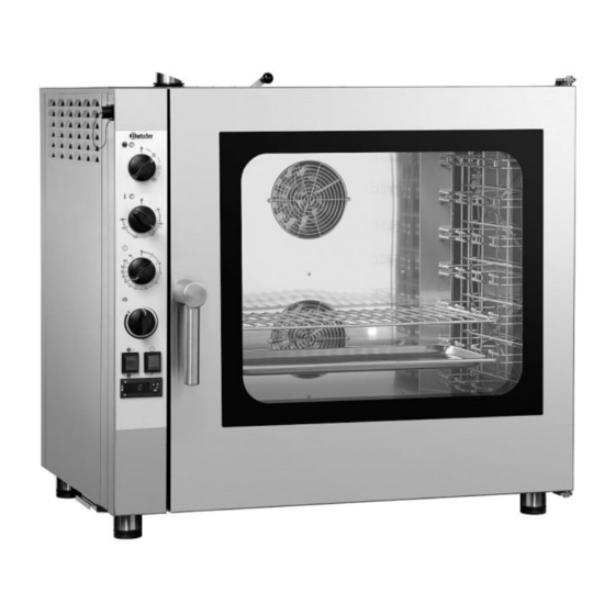
Technical Data List of Components of the Appliance Fig. 1 1. Housing 2. Control panel 3. Ventilation openings 4. Thermal core probe connection 5. Fume extractor 6. Humidity discharge valve 7. Fan (2 pcs) 8. Guide rails 9. Door 10. Door handle 11. -
Page 18: Installation Instructions
Installation Instructions Installation Instructions Installation CAUTION! Incorrect installation, positioning, operation, maintenance or misuse of the appliance may lead to personal injury or property damage. Positioning and installation, as well as repairs may be performed by authorised technical service only and in compliance with the applicable national law. - Page 19 Installation Instructions • The appliance must be transported to the installation location in packaging, on its dedicated wooden pallet. • Transportation must be executed with the use of pallet trolley, observing all safety precautions, in order to avoid the risk of tipping it over. Also, following the operation period, the oven must be transported on a pallet and manipulate with the highest caution, in order to avoid the risk of tipping it over.
- Page 20 Installation Instructions • Be careful not to damage the rating plate and warning labels affixed to the appliance. • Remove all accessories, information materials, and plastic bags from the appliance. • Check if ventilation openings and fume extractor are not covered nor obstructed in any way.
- Page 21 Installation Instructions Water Connection • Make sure that the potable water connection is located close to the appliance. • In new installation is carried out, before the appliance is connected to water supply system, drain sufficient amount of water to prevent contamination of magnetic valves.
- Page 22 Installation Instructions Drain Connection To provide for liquid drainage from the thermal processing chamber, the appliance is equipped with water drain. The connection (A, Fig. 5) is located at the bottom right side of the back of the appliance, and features 32 mm diameter.
- Page 23 Installation Instructions The appliance is delivered with a certified power cord and plug: it is prohibited to manipulate them or modify them. Potential Equalising Connection • The potential equalising connection between various appliances should be executed at the connection clamp, marked with symbol.
-
Page 24: Inspections And Commissioning Test
Installation Instructions Inspections and Commissioning Test Inspections Prior to Start-up Before the first start-up, electric appliances must be thoroughly inspected in order to confirm the consistency of the appliance and its installation with regulations in force, technical data, and recommendations for safety. The following conditions must be met: –... -
Page 25: Operating Instruction
Operating Instruction Inspection During Commissioning When commissioning, the following conditions must be met: – Internal lighting switches on automatically. – The appliance is switched off after opening the door and is switched on again after closing it. – The temperature setting thermostat in the appliance is triggered only when the set temperature is reached. - Page 26 Operating Instruction • Never install the appliance in the vicinity of heat sources, such as a grill or a deep-fryer. • Never leave flammable materials near the appliance. Fire hazard! • Do not put flammable materials nor food products containing alcohol in the combi steamer: it may cause self-ignition and fire that, in turn, may lead to an explosion.
- Page 27 Operating Instruction NOTE! Before cooking/roasting, heat the appliance up to the temperature higher than the intended cooking/roasting temperature by 20-25%. After reaching the pre-heating temperature, the appliance may be loaded. The temperature should then be reduced to the temperature provided for the preparation of the dish.
-
Page 28: Control Panel
Operating Instruction Control Panel • Prior to firs t operation, cl ean the appli anc e and its equi pment ac cor ding to i nstr ucti ons in sect ion 6 'Cleaning'. Make sur e no water enters el ectric i nstallation and connec tion box. N astępni e dokł adni e osus z yć urz ądz enie i el ementy wypos aż eni a. •... -
Page 29: Settings
Operating Instruction Settings Prior to firs t operation, cl ean the appli anc e and its equi pment ac cor ding to i nstr ucti ons in sect ion 6 'Cleaning'. Make sur e no water enters el ectric i nstallation and connec tion box. T hen thoroughl y dr y the appli anc e and the entire eq uipm ent. •... - Page 30 Operating Instruction Cooking/roasting with steam 1. To set the cooking/roasting with steam, rotate the M 1 function selector knob clockwise to I 3 position. 2. Then, set the temperature by rotating the M 2 temperature controller clockwise to the selected position. For traditional cooking/roasting with steam, it is recommended to set the appliance to 110°C, which is marked as I...
- Page 31 Operating Instruction Combi steaming (cooking/roasting with air circulation/steam) 1. To set the cooking/roasting with air circulation/steam, rotate the M 1 function selector knob clockwise to I 4 position. 2. Then, set the temperature by rotating the M 2 temperature controller clockwise to the selected position.
- Page 32 Operating Instruction Cooking/roasting with thermal core probe 1. Us the M 1 function selector knob to select the cooking/roasting mode, rotating it to one of the following positions: I 2 – I 3 – I 4. 2. Set the temperature by rotating the M 2 temperature controller clockwise to the selected position.
- Page 33 Operating Instruction Thermal Core Probe Connection 1. To connect the thermal core probe, remove the plug A (Fig. 12) from the connection location in the upper left corner of the appliance. 2. Press and hold the red lock B and insert the thermal core probe C (Fig.
- Page 34 Operating Instruction Humidity Discharge Valve The humidity extraction function consists in removal of humidity that may condense in the thermal processing chamber during cooking/roasting process. 1. Set the discharge valve lever L1 to the following positions: P1 left: VALVE CLOSED P2 right: VALVE OPEN Also, when the discharge vale is closed, there is no threat of overpressure in the...
- Page 35 Operating Instruction Recommendations for cooking Roasting For more effective cooking, it is recommended to place the roasted foods on the steel rod grill in order to achieve more uniform cooking between the upper and lower part without having to turn the product during cooking. If you want to collect the juices, place a tray below the grill in the rails.
-
Page 36: Cleaning And Maintenance
Cleaning and Maintenance Pasteurisation in a container In that process the product is considered pasteurised when the core temperature reaches a value between 83 °C and 85 °C. Depending on the type of product, dimensions of the container and amount of product it contains, the time of reaching the core temperature may vary. -
Page 37: Cleaning
Cleaning and Maintenance Cleaning User's Regular Cleaning 1. To secure correct operation, hygiene and efficiency, clean the appliance regularly at the end of each working day, and, if necessary, also in the meantime or when the appliance is not to be used for a longer time. With regular cleaning you may avoid burning leftovers of baked goods and roasts. - Page 38 Cleaning and Maintenance Appliance Door/Internal Glass Pane Double glazing facilitates cleaning. The internal glass pan may be opened and removed when required. 1. To this end, rotate clockwise both latches (top and bottom) that hold the internal glass pane in place (Fig. 18). 2.
-
Page 39: Maintenance
Possible Malfunctions If the ventilation filter is damaged or worn, it must be replaced. It should be ordered as a spare part from the supplier. Maintenance • Regularly (at least once a year), have an authorized and specialised personnel verify the appliance. To this end, contact the service company. •... -
Page 40: Disposal
Disposal Error Solution If the appliance does not switch on following the actions above, contact the service company. Fan stops during Switch the appliance off and wait for the motor overheating operation protection to be automatically re-set Make sure that ventilation openings are not covered nor obstructed If the malfunction persists, contact the service company Water does not...