Table of Contents

Related Manuals for Bender ISOMETER isoMIL425


Summary of Contents for Bender ISOMETER isoMIL425
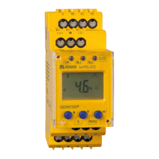
- Page 1 Manual ISOMETER® isoMIL425 Insulation monitoring device for unearthed IT AC-, AC/DC and DC systems (IT systems) in military applications up to 3(N)AC, AC/DC 400 V Software version: D0459 V1.xx isoMIL425_D00203_03_M_XXEN/03.2019...
- Page 2 Bender GmbH & Co. KG Londorfer Str. 65 • 35305 Gruenberg • Germany P.O. Box 1161 • 35301 Gruenberg • Germany Tel.: +49 6401 807-0 Fax: +49 6401 807-259 E-mail: info@bender.de Web: http://www.bender.de © Bender GmbH & Co. KG All rights reserved.
-
Page 3: Table Of Contents
Table of contents 1. Important information ..................6 How to use this manual ................. 6 Technical support: Service and support ..........7 1.2.1 First level support ..................... 7 1.2.2 Repair service ..................... 7 1.2.3 Field service ......................8 Training courses ....................8 Delivery conditions .................. - Page 4 Table of contents 3.2.10 External, combined test or reset button T/R ........22 3.2.11 Fault memory ....................22 3.2.12 History memory HiS ..................23 3.2.13 Interface/protocols ..................23 4. Installation, connection and commissioning ........... 25 Installation ....................... 25 Wiring diagram ....................27 Commissioning ....................
- Page 5 Table of contents 7. Data access using the Modbus RTU protocol ........... 42 Reading out the Modbus register from the ISOMETER® ....42 7.1.1 Command of the master to the ISOMETER® ........42 7.1.2 Answer of the ISOMETER® to the Master ..........43 Write Modbus register (parameter setting) .........
-
Page 6: Important Information
1. Important information 1.1 How to use this manual This manual is intended for electrically skilled persons working in electrical engineering and electronics. Always keep this manual within easy reach for future reference. To make it easier for you to understand and revisit certain sections in this man- ual, we have used symbols to identify important instructions and information. -
Page 7: Technical Support: Service And Support
1.2 Technical support: Service and support For commissioning and troubleshooting Bender offers you: 1.2.1 First level support Technical support by phone or e-mail for all Bender products Questions concerning specific customer applications Commissioning ... -
Page 8: Field Service
**Mon-Thurs 7.00 a.m. - 8.00 p.m., Fr 7.00 a.m. - 13.00 p.m. 1.3 Training courses Bender is happy to provide training regarding the use of test equipment. The dates of training courses and workshops can be found on the Internet at www.bender-de.com ->... -
Page 9: Delivery Conditions
ZVEI (Zentralverband Elektrotechnik- und Elektronikindus- trie e.V.) (German Electrical and Electronic Manufacturers' Association) also applies. Sale and delivery conditions can be obtained from Bender in printed or elec- tronic format. 1.5 Inspection, transport and storage Inspect the dispatch and equipment packaging for damage, and compare the contents of the package with the delivery documents. -
Page 10: Disposal
13th August 2005 must be taken back by the manufacturer and disposed of prop- erly. For more information on the disposal of Bender devices, refer to our homepage at www.bender.de -> Service & support. isoMIL425_D00203_03_M_XXEN/03.2019... -
Page 11: Safety Instructions
2. Safety instructions 2.1 General safety instructions Part of the device documentation in addition to this manual is the enclosed "Safety instructions for Bender products". 2.2 Work activities on electrical installations Only skilled persons are permitted to carry out the work necessary to install, commission and run a de- vice or system. -
Page 12: Intended Use
Safety instructions 2.3 Intended use The ISOMETER® monitors the insulation resistance R (R mode) or the insula- tion impedance Z (Z mode) of unearthed AC/DC main circuits (IT systems) with nominal system voltages of 3(N)AC, AC, AC/DC or DC 0 … 400 V. DC com- ponents existing in 3(N)AC, AC/DC systems do not influence the operating characteristics, when a minimum load current of DC 10 mA flows. -
Page 13: Function
RS-485 (galvanically isolated) including the following protocols: – BMS interface (Bender measuring device interface) for data exchange with other Bender components – Modbus RTU – IsoData (for continuous data output) Password protection to prevent unauthorised parameter changes ... -
Page 14: Functional Description
Function 3.2 Functional description The ISOMETER® measures the insulation resistance R and the system leakage capacitance C between the system to be monitored (L1/+, L2/-) and earth (PE). Z mode (selectable in the "SEt" menu) calculates the insulation imped- ance Z from R and C with a system frequency parameter f... -
Page 15: Monitoring Of The Insulation Resistance (R Mode)
Function "K2" according to the alarm assignment set in the "out" menu. In addition, the operation of the relay (n.o./n.c.) can be set and the fault memory "M" activat- If the values R or U do not exceed their release value (response value plus hysteresis) for the period t without interruption, the alarm relays will switch back to their initial position and the alarm LEDs "AL1"/"AL2"... -
Page 16: Monitoring Of The Insulation Impedance (Z Mode)
Function 3.2.2 Monitoring of the insulation impedance (Z mode) The parameters "Z1" and "Z2" for monitoring the insulation impedance Z available in the "AL" response value menu only when Z mode is activated. The value "Z1" must be set higher than value "Z2". The insulation impedance Z the selected system frequency f (50 Hz or 60 Hz in the "SEt"... -
Page 17: Self Test/Error Codes
Function 3.2.4 Self test/error codes The integrated self-test function checks the function of the insulation moni- toring device and the connection monitoring checks the connections to the system to be monitored. The alarm relays are not switched during the self test. This can be changed using the parameter "test"... - Page 18 Function The maximum permissible system leakage capacitance is exceeded. Action: E.07 Device not suitable for the existing system leakage capaci- tance C : uninstall device. Calibration error during the device test Action: E.08 If the error continues to exist after checking the device con- nections, there is an error inside the device.
-
Page 19: Malfunction
LEDs "ON"/"AL1"/ "AL2" will flash. If the error occurs again after restarting the device or after a reset to factory settings, then contact Bender Service. 3.2.6 Assignment of the alarm relays K1/K2 The messages "device error", "insulation fault", "insulation impedance fault",... -
Page 20: Measuring And Response Times
Function L2/-. If an assignment is not possible, for example in the event of a symmetri- cal insulation fault, the message corresponding to "+" and "- " are shown to- gether. The message "test" indicates a self test. The message "S.AL" indicates a so-called "device start with alarm". After con- necting to the supply voltage U and setting the parameter value to "S.AL = on", the ISOMETER®... - Page 21 Function Operating time The operating time t is the time required by the ISOMETER® to determine the measuring value. The insulation resistance measuring value depends on the the insulation resistance R and the system leakage capacitance C . For ex- ample, a maximum permissible system leakage capacitance of C = 300 μF and an insulation fault of R...
-
Page 22: Password Protection (On, Off)
Function Start-up delay After connection to the supply voltage U the alarm indication for the preset time (0…10 s) in the parameter "t" is suppressed. 3.2.8 Password protection (on, OFF) If password protection has been activated (on), settings can only be made subject to the correct password being entered (0...999). -
Page 23: History Memory His
The ISOMETER® uses the serial hardware interface RS-485 with the following protocols: The BMS protocol is an essential component of the Bender measuring device interface (BMS bus protocol). ASCII characters are used for the data transfer. Modbus RTU ... - Page 24 Function With "Adr = 0", the menu entries "baud rate" and "parity" are not shown in the menu and the IsoData protocol is activated. With a valid bus address (i.e. not equal to 0), the menu item "baud rate" is displayed in the menu. The parameter value "---"...
-
Page 25: Installation, Connection And Commissioning
4. Installation, connection and commissioning Risk of electric shock! Touching uninsulated live conductors can result in death or serious injury. Therefore avoid any physical contact with DANGER active conductors and ensure compliance with the regulations for working on electrical installations. 4.1 Installation DIN rail mounting: ... - Page 26 Installation, connection and commissioning The dimension diagram, sketch for screw mounting and DIN rail mounting are shown below: Click! Click & All dimensions in mm The front plate cover can be opened at the lower part marked with an arrow. isoMIL425_D00203_03_M_XXEN/03.2019...
-
Page 27: Wiring Diagram
Installation, connection and commissioning 4.2 Wiring diagram L1/+ L2/- L1/+ COM465IP Test / Reset isoMIL425 RS-485 For details about the conductor cross sections required for wiring, refer to the technical data on Page isoMIL425_D00203_03_M_XXEN/03.2019... - Page 28 Installation, connection and commissioning Wiring diagram legend: Terminal Connections Connection to the supply voltage U via fuse (line protection): A1, A2 If supplied from an IT system, both lines have to be protected by a fuse.* Connect each terminal separately to PE: E, KE The same wire cross section as for "A1", "A2"...
-
Page 29: Commissioning
Installation, connection and commissioning 4.3 Commissioning 1. Check that the ISOMETER® is properly connected to the system to be monitored. 2. Connect the supply voltage U to the ISOMETER® The device carries out a calibration, a self test and adjusts itself to the IT system to be monitored. -
Page 30: Operation Of The Device
5. Operation of the device The menu structure is illustrated schematically on the following pages. After pressing the "MENU" button for > 1.5 s, the first menu item "AL" appears. (Enter) buttons for navigation and settings. Up and down button: - to navigate up or down the menu settings - increasing or decreasing values Pressing the MENU/Enter button for more than... -
Page 31: Display Elements
Operation of the device 5.1 Display elements Device front/display Function green - on Assignment according to yellow - alarm table on Page 34 yellow - alarm AL1 AL2 Up button Test button ( press > 1.5 s) Down button Reset button (press > 1.5 s) ENTER MENU MENU button (press >... -
Page 32: Menu Structure
Operation of the device 5.2 Menu structure Measurement display Standard display Menu selection Menu Enter t > 5 min. Z [kΩ] Enter R [kΩ] C [μF] Parameter selection U L1 L2 [ V] UL1 [ V] UL2 [ V] . . . R [ %] U R [kΩ] Enter... -
Page 33: Menu "Al
Operation of the device 5.3 Menu "AL" 5.3.1 Response value setting Only after activating Z mode in the "SEt" menu, the response values "Z1" as well as "Z2" appear on the display and are activated. Simultaneously, the re- sponse values "R1" and "R2" are set to position off, but can then be set to on again. -
Page 34: Menu "Out
Operation of the device 5.4 Menu "out" 5.4.1 Configuration of the relay operating mode Relay K1 Relay K2 Description Display Display Operating mode of n.c. n.c. the relay n.c./n.o. FAC = Factory setting; Cs = User settings 5.4.2 Relay alarm assignment "r1" and "r2" and LED assignment In the alarm assignment, each alarm is assigned to the corresponding relay with the setting "on". -
Page 35: Fault Memory Configuration
Operation of the device Alarm K1 "r1" K2 "r2" LEDs description ON AL1 AL2 Display Display Pre-alarm Z1 Z1 < Ω Z1 < Ω Alarm Z2 < Ω Z2 < Ω Alarm ... -
Page 36: Interface Configuration
Operation of the device 5.4.4 Interface configuration Display Setting value Description Range Adr = 0 deactivates BMS as well as Modbus and Bus- 0 / 3 … 90 activates isoData with con- Adr. tinuous data output (115k2, 8E1) “---“ : BMS bus (9k6, 7E1) Baud “---“... -
Page 37: Menu "T
Operation of the device 5.5 Menu "t" 5.5.1 Time configuration Display Setting value Description Alarm assignment s Start-up delay when starting the 0 … 10 device s Response delay K1 and K2 0 … 99 s Delay on release K1 and K2 toff 0 …... -
Page 38: Menu "Set
50.0 / and select associated 50.0 60.0 system frequency f Test the system connec- tion during device test S.Ct Device test during device start Restore factory settings For Bender Service only FAC = Factory setting; Cs = User settings isoMIL425_D00203_03_M_XXEN/03.2019... -
Page 39: Measuring Value Display And History Memory
Operation of the device 5.7 Measuring value display and history memory In R mode only R and in Z mode only Z is permanently shown on the display (standard display). All other measuring value displays switch to the standard display after a maximum of 5 min. The fault location will only be stored in the history memory ("HiS") in R mode. - Page 40 Operation of the device Display Description Insulation impedance kΩ 1 kΩ ... 1 MΩ Resolution 1 kΩ Insulation resistance ± R kΩ 1 kΩ ... 4 MΩ Resolution 1 kΩ / 10 kΩ System leakage capacitance Z mode = off: 1 μF … 300 μF Resolution 1 μF μF Z mode = on: 1 nF …...
-
Page 41: Data Access Using The Bms Protocol
6. Data access using the BMS protocol The BMS protocol is an essential component of the Bender measuring device interface (BMS bus protocol). ASCII characters are used for the data transfer. BMS channel Operation value Alarm Pre-alarm R1 Alarm R2... -
Page 42: Data Access Using The Modbus Rtu Protocol
7. Data access using the Modbus RTU protocol Requests to the ISOMETER® can be made using the function code 0x03 (read multiple registers) or the command 0x10 (write multiple registers). The ISOMETER® generates a function-related answer and sends it back. 7.1 Reading out the Modbus register from the ISOMETER®... -
Page 43: Answer Of The Isometer® To The Master
Data access using the Modbus RTU protocol 7.1.2 Answer of the ISOMETER® to the Master Byte Name Example Byte 0 ISOMETER® Modbus address 0x03 Byte 1 Function code 0x03 Byte 2 Number of data bytes 0x02 Byte 3, 4 Data 0x0047 Byte 7, 8 CRC16 Checksum... -
Page 44: Isometer® Answer To The Master
Data access using the Modbus RTU protocol 7.2.2 ISOMETER® answer to the Master Byte Name Example Byte 0 ISOMETER® Modbus address 0x03 Byte 1 Function code 0x10 Byte 2, 3 Start register 0x0BBB Byte 4, 5 Number of registers 0x0001 Byte 6, 7 CRC16 Checksum 0x722A... -
Page 45: Modbus Register Assignment Of The Isometer
8. Modbus register assignment of the ISOMETER® The information in the registers is the measuring value without alarm, the measuring value with alarm 1, the measuring value with alarm 2 or only the device fault, depending on the device condition. Measuring value Register Device fault... - Page 46 Modbus register assignment of the ISOMETER® Measuring value Register Device fault Without Alarm 1 Alarm 2 alarm 1016 Voltage (76) [no alarm] 1019 1020 Voltage (76) [no alarm] 1023 Fault location 1024 in % --- (1022) 1027 [no alarm] 1028 Insulation fault (71) 1031...
- Page 47 Modbus register assignment of the ISOMETER® Permissions Description Format Unit Value range Register Number of Mod- UINT 16 0…9 bus measured value channels with active alarm Activation of pre- UINT 16 [2]/[3] * alarm value 3000 impedance meas- urement "Z1" Pre-alarm value 3001 impedance...
- Page 48 Modbus register assignment of the ISOMETER® Permissions Description Format Unit Value range Register Activation alarm value resist- 0/1/[2]/[3] * 3006 UINT 16 ance measurement "R2" Alarm value 3007 resistance UINT 16 kΩ 1 … R1 measurement "R2" Activation alarm value 0/1 * 3008 UINT 16...
- Page 49 Modbus register assignment of the ISOMETER® Permissions Description Format Unit Value range Register 0 = BMS 1 = 1.2 k 2 = 2.4 k 3 = 4.8 k 3016 Baud rate "Adr 1" UINT 16 4 = 9.6 k 5 = 19.2 k 6 = 38.4 k 7 = 57.6 k 8 = 115.2 k...
- Page 50 Modbus register assignment of the ISOMETER® Permissions Description Format Unit Value range Register Parameter "Z": 500 = 50.0 3023 System fre- UINT 16 quency f for Z 600 = 60.0 mode Test of the sys- tem connection 0/1 * 3024 UINT 16 during device test "nEt"...
-
Page 51: Device-Specific Data Type Of The Isometer
Modbus register assignment of the ISOMETER® Permissions Description Format Unit Value range Register UNIT 16 (ASCII) - 9800 Device name refer to to 9809 Chapter 8.1.1 Software Software ID 9820 UINT 16 ID number number Software version Software 9821 UINT 16 number version Software... -
Page 52: Measuring Values
Modbus register assignment of the ISOMETER® 8.1.2 Measuring values Each measuring value is available as a channel and consists of 8 bytes (4 registers). The first measuring value register address is 1000. The structure of a channel is always identical. Content and number depend on the device. The structure of a channel is shown with the example of channel 1: 1000 1001... -
Page 53: Float = Floating Point Value Of The Channels
Modbus register assignment of the ISOMETER® 8.1.2.1 Float = Floating point value of the channels 0x00 0x01 HiByte LoByte HiByte LoByte S E E E E E E E E M M M M M M M M M M M M M M M M M M M M M M M Presentation of the bit order for processing analogue measuring values ac- cording to IEEE 754 S = Sign... -
Page 54: At&T = Alarm Type And Test Type (Internal/External)
Modbus register assignment of the ISOMETER® 8.1.2.2 AT&T = Alarm type and test type (internal/external) Meaning No alarm Prewarning Device error Reserved Warning Alarm Reserved … … … Reserved Reserved No test Internal test External test The alarm type is coded by bits 0 to 2. Bits 3, 4 and 5 are reserved and always have the value 0. -
Page 55: R&U = Range And Unit
Modbus register assignment of the ISOMETER® 8.1.2.3 R&U = Range and unit Meaning Invalid (init) No unit Ω Baud °C °F Second Minute Hour Month Actual value The actual value is lower The actual value is higher Invalid value The units of bits 0 to 4 are coded. ... -
Page 56: Alarm Assignment Of The Relays
Modbus register assignment of the ISOMETER® 8.1.3 Alarm assignment of the relays Several alarms can be assigned to each relay. For the assignment of each relay, a 16-bit-register is used with the bits described below. The following table ap- plies to relay 1 and relay 2, in which "x" stands for the relay number. A set bit activates the specified function. -
Page 57: Channel Descriptions
Modbus register assignment of the ISOMETER® Display indication Meaning When reading, always 0 Reserved When writing, any value When reading, always 0 Reserved When writing, any value When reading, always 0 Reserved When writing, any value 8.2 Channel descriptions Measuring value description / Alarm Parameter Note... - Page 58 Modbus register assignment of the ISOMETER® To convert parameter data, data type descriptions are required. Text representation is not necessary in this case. Parameter Description of parameters 1023 (0x3FF) Parameter/measured value invalid. The menu item of this parameter is not displayed. 1022 (0x3FE) No measured value/no message 1021 (0x3FD) Measured value/parameter inactive 1020 (0x3FC) Measured value/parameter only temporarily inactive (e.g.
-
Page 59: Isodata Data String
9. IsoData data string In IsoData mode, the ISOMETER® continuosly sends the whole data string with a cycle time of approximately 1 s. Communication with the ISOMETER® within this mode is not possible and no additional sender may be connected via the RS-485 bus cable. - Page 60 IsoData data string String Description Alarm message [hexadecimal] (without leading "0x") The alarms are included in this value with the OR function. Assignment of the alarms: 0x0002 Device fault 0x0004 Prewarning insulation resistance R at L1/+ 0x0008 Prewarning insulation resistance R at L2/- 0x000C Prewarning insulation resistance R symmetrical...
-
Page 61: Technical Data
10. Technical data 10.1 Tabular presentation ( )* = factory setting Insulation coordination acc. to IEC 60664-1/IEC 60664-3 Definitions: Measuring circuit (IC1) ...........................L1/+, L2/- Supply circuit (IC2) ............................A1, A2 Output circuit (IC3)........................... 11, 14, 24 Control circuit (IC4) ...........................E, KE, T/R, A, B Rated voltage................................. - Page 62 Technical data Frequency range U ............................. 47…63 Hz Power consumption ..........................≤ 3 W, ≤ 9 VA IT system being monitored Nominal system voltage U ....................3(N)AC, AC/DC 0…400 V Tolerance of U ..............................+25 % Frequency range of U ........................
- Page 63 Technical data Displays, memory Display..................... LC display, multi-functional, not illuminated Display range measured value insulation resistance (R ) ................ 1 kΩ…4 MΩ Display range measured value impedance (Z ) with f = 50 / 60 Hz............. 1 kΩ…1 MΩ in R mode, Z Operating uncertainty (R in Z mode)...............
- Page 64 Technical data Environment/EMC EMC .......................... IEC 61326-2-4, DIN EN50121-3-2 Ambient temperatures: Operation ..............................-40…+70 ºC Transport ..............................-50…+85 ºC Storage ..............................-55…+80 ºC Climatic class acc. to IEC 60721: Stationary use (IEC 60721-3-3)..........................3K7 Transport (IEC 60721-3-2) ............................2K4 Long-time storage (IEC 60721-3-1)........................1K6 Classification of mechanical conditions acc.
-
Page 65: Standards, Approvals And Certifications
Technical data Other Operating mode ........................... continuous operation Mounting ..................... cooling slots must be ventilated vertically Degree of protection, built-in components (DIN EN 60529) ................. IP30 Degree of protection, terminals (DIN EN 60529) ....................IP20 Enclosure material ............................ polycarbonate DIN rail mounting acc. to..........................IEC 60715 Screw fixing ......................... - Page 66 INDEX Alarm assignment of the relays 34 History memory 23 How to use this manual 6 Commissioning 29 Configuration Installation and connection 25 - Fault memory 35 Interface/protocols - Function 38 - BMS 23 - Interface 36 - IsoData 23 - Relay operating mode 34 - Modbus RTU 23 - Time 37...
- Page 67 Monitoring - Insulation impedance (Z mode) 16 Wiring diagram 27 - insulation resistance (R mode) 15 Work activities on electrical installations 11 - undervoltage and overvoltage 16 Operating time 21 Operation 30 Ordering information 65 Password protection 22 Reset button T/R 22 Response delay 21 Response times 20 Response value setting 33...
- Page 68 Bender GmbH & Co. KG Londorfer Str. 65 • 35305 Gruenberg • Germany P.O. Box 1161 • 35301 Gruenberg • Germany Tel.: +49 6401 807-0 Fax: +49 6401 807-259 E-mail: info@bender.de Web: http://www.bender.de Photos: Bender archive.
Need help?
Do you have a question about the ISOMETER isoMIL425 and is the answer not in the manual?
Questions and answers