Sign In
Upload
Manuals
Brands
Bender Manuals
Measuring Instruments
ISOMETER isoMIL425
Bender ISOMETER isoMIL425 Manuals
Manuals and User Guides for Bender ISOMETER isoMIL425. We have
1
Bender ISOMETER isoMIL425 manual available for free PDF download: Manual
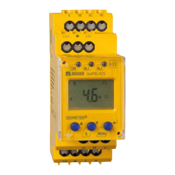
Bender ISOMETER isoMIL425 Manual (68 pages)
Insulation monitoring device for unearthed IT AC-, AC/DC and DC systems (IT systems)
Brand:
Bender
| Category:
Measuring Instruments
| Size: 1 MB
Table of Contents
Table of Contents
3
1 Important Information
6
How to Use this Manual
6
Technical Support: Service and Support
7
First Level Support
7
Repair Service
7
Field Service
8
Training Courses
8
Delivery Conditions
9
Inspection, Transport and Storage
9
Warranty and Liability
9
Disposal
10
2 Safety Instructions
11
General Safety Instructions
11
Work Activities on Electrical Installations
11
Intended Use
12
3 Function
13
Device Features
13
Functional Description
14
Monitoring of the Insulation Resistance (R Mode)
15
Monitoring of the Insulation Impedance (Z Mode)
16
Undervoltage/Overvoltage Monitoring
16
Self Test/Error Codes
17
Malfunction
19
Assignment of the Alarm Relays K1/K2
19
Measuring and Response Times
20
Password Protection (On, OFF)
22
Factory Setting FAC
22
External, Combined Test or Reset Button T/R
22
Fault Memory
22
History Memory His
23
Interface/Protocols
23
4 Installation, Connection and Commissioning
25
Installation
25
Wiring Diagram
27
Commissioning
29
5 Operation of the Device
30
Display Elements
31
Menu Structure
32
Menu "AL
33
Response Value Setting
33
Menu "Out
34
Configuration of the Relay Operating Mode
34
Relay Alarm Assignment "R1" and "R2" and LED Assignment
34
Fault Memory Configuration
35
Interface Configuration
36
Menu "T
37
Time Configuration
37
Menu "Set
38
Function Configuration
38
Measuring Value Display and History Memory
39
6 Data Access Using the BMS Protocol
41
7 Data Access Using the Modbus RTU Protocol
42
Reading out the Modbus Register from the ISOMETER
42
Command of the Master to the ISOMETER
42
Answer of the ISOMETER® to the Master
43
Write Modbus Register (Parameter Setting)
43
Command of the Master to the ISOMETER
43
ISOMETER® Answer to the Master
44
Exception Code
44
Structure of the Exception Code
44
8 Modbus Register Assignment of the ISOMETER
45
Device-Specific Data Type of the ISOMETER
51
Device Name
51
Measuring Values
52
Float = Floating Point Value of the Channels
53
AT&T = Alarm Type and Test Type (Internal/External)
54
R&U = Range and Unit
55
Alarm Assignment of the Relays
56
Channel Descriptions
57
9 Isodata Data String
59
10 Technical Data
61
Tabular Presentation
61
Standards, Approvals and Certifications
65
Ordering Information
65
Advertisement
Advertisement
Related Products
Bender ISOMETER isoMIL425HV
Bender ISOMETER isoMIL685W-D-P
Bender ISOMETER IRDH275
Bender ISOMETER isoPV with AGH-PV
Bender isoMED427
Bender isoMED427P-CX
Bender ISOMETER IR1570W-435
Bender ISOMETER IR1575W-435
Bender ISOMETER IR1575-434
Bender ISOMETER IR1570
Bender Categories
Measuring Instruments
Monitor
Control Unit
Control Panel
Relays
More Bender Manuals
Login
Sign In
OR
Sign in with Facebook
Sign in with Google
Upload manual
Upload from disk
Upload from URL