
Related Manuals for ARTHUR HOLM AH10DB2


Summary of Contents for ARTHUR HOLM AH10DB2
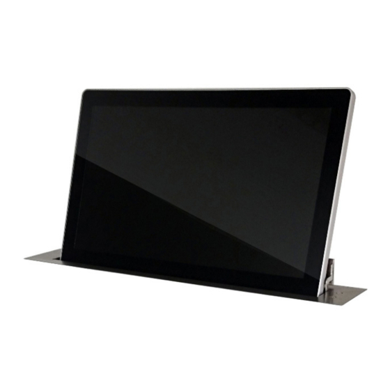
- Page 1 User Guide AH10DB2 AH17DB2 AH22DB2 HDCP compliant retractable monitor for furniture integration Technology Serving Desing Danish craftmanship Mediterranean soul...
-
Page 3: Table Of Contents
TABLE OF CONTENTS EC REGULATIONS AND SECURITY SAFETY INSTRUCTIONS SYSTEM DESCRIPTION CONTROLS OSD MENU INPUT CONNECTORS AHNET PROTOCOL INPUT SIGNALS INFORMATION ON DISPOSAL WARRANTY TERMS AND CONDITIONS... - Page 4 WELCOME Thank you for purchasing an ARTHUR HOLM product. Our product range has been designed for a seamless integration and for a maximum reliability. Please, read this installation and operating instructions carefully and keep them in a safe place for future reference.
- Page 5 ABOUT US The Company Arthur Holm has its origins in the Danish furniture designer Jorgen Alex Jensen, who was active during the sixties and the seventies. His design inspiration and his concept of ergonomics have been continued by his family, who is the design force behind Arthur Holm product range. The...
-
Page 6: Ec Regulations And Security
EC REGULATIONS AND SECURITY ATTENTION: Do not disassemble or modify the device in any way. This symbol warns of the presence of dangerous un-insulated voltages inside some of the components, of sufficient magnitude to expose people to risk of electronic shock. This symbol draws attention to important use and maintenance instructions in the manual that accompanies the unit. - Page 7 SAFETY INSTRUCTIONS Wiring connected to hazardous voltage requires installation by qualified personnel or the use of ready-made flexible cables. For your security, your equipment must be connected to an electrical outlet with grounding connection protection. Since the plug is used to disconnect the device, the operating electrical outlet must be in an easily accessible place.
-
Page 8: System Description
The monitors are equipped with AH-AMMC: An auto mechanical calibration movement system. The use of the Arthur Holm’s ERT will enable the address configuration of all the monitors installed in a table by simply pressing... - Page 9 SYSTEM DESCRIPTION Features • Vertical motorised monitor with up to 20° inclination. • Adjustable screen angle tilt. • No cover plate required (monitor completey streamlined within the furniture). • One operation sensor on top of the aluminium housing (to rise and lower the screen and adjust the tilt angle).
- Page 10 SYSTEM DESCRIPTION Connections Before connecting the power: 1. Install the unit on a table or desk, in vertical position. Power connection: 1. Plug the power cable from the power supply into an AC socket of 100-240 Vac, 50-60Hz. 2. Plug the 12Vdc cable into the socket on the unit. Signal connection: 1.
-
Page 11: Controls
CONTROLS Remote control POWER Switch ON/OFF the monitor MENU Activates the OSD menu on screen Cursor control up on the OSD menu DOWN Cursor control down on the OSD menu LEFT Cursor control left on the OSD menu RIGHT Cursor control right on the OSD menu Selects the function on the OSD menu. - Page 12 CONTROLS IR sensor The IR sensor is located on the lower right side of the screen. Monitor movement controls On the upper panel body, and on front of the glass, there is a button to control the UP and DOWN monitor movements, and the screen tilting angle.
- Page 13 CONTROLS Tilting the screen: When the monitor is up, permanent press the button to control the tilt screen angle. Pressing and holding this button makes the monitor tilt up and down in a cycle. Release the button when the monitor is at the desired angle.
-
Page 14: Osd Menu
OSD MENU Accessing the menu system • With the OSD off, push the MENU button to activate the main OSD menu. • Press the UP and DOWN buttons to move from one function to another. Please refer to the following sections below to view a complete list of all the functions available for the monitor. - Page 15 OSD MENU Picture Noise Reduction: Adjusts the image noise filter ∙ Off ∙ Low ∙ Medium ∙ High ∙ Default Screen: (Only for analogue signals) ∙ Auto Adjust ∙ Horizontal Position ∙ Vertical Position ∙ Size ∙ Phase Backlight: Adjusts the backlight screen level Colour Range: Adjusts the colour range ∙...
- Page 16 OSD MENU Setup Language: OSD language selection Restore Factory Default: Adjusts the parameters to the initial factory parameters Blending: OSD window transparency ∙ Low ∙ Medium ∙ High ∙ Off OSD Duration: Adjusts the time that the OSD menu window remains on screen Software Update: Used for firmware upgrade mirror Mirror:...
-
Page 17: Input Connectors
INPUT CONNECTORS DVI 1/ DVI A: DVI-I input signal. Connect a DVI (digital) input signal and select DVI 1 on the OSD monitor menu. Use a DVI to VGA adapter to connect an ARGB (analogue) input signal and select DVI-A on the OSD monitor menu. -
Page 18: Ahnet Protocol
AHNET PROTOCOL Communications protocol COMMUNICATION RS422 CONNECTION RJ45 WIRING CAT-5 Speed and configuration BAUD RATE 38400 DATA BITS PARITY NONE STOP BITS Wiring Diagram 1. Data TX + 2. Data TX – 3. Data RX + 4. NC 5. NC 6 .Data RX –... - Page 19 AHNET PROTOCOL AHnet protocol Using 5 bytes communication: BYTE 0 START BYTE BYTE 1 ADDRESS BYTE BYTE 2 COMMAND BYTE BYTE 3 VALUE 1 BYTE 4 VALUE 2 Commands COMMAND DESCRIPTION RESPONSE FA XX 01 01 00 GO UP FB XX 01 01 00 FA XX 01 00 00 GO DOWN FB XX 01 00 00...
- Page 20 AHNET PROTOCOL BITE CLOSED OPENED SCREEN ON SCREEN OFF DVI 1-A DVI 1-D DVI 2-D PROTECTION STOP MONITOR OK BITE BUTTON LOCK BUTTON UNLOCK...
- Page 21 AHNET PROTOCOL Picture Commands COMMAND DESCRIPTION RESPONSE FA XX 15 00 00 ASK FOR BACKLIGHT LEVEL FB XX 15 00 ZZ FA XX 16 00 00 ASK FOR CONTRAST LEVEL FB XX 16 00 ZZ FA XX 17 00 00 ASK FOR BRIGHTNESS LEVEL FB XX 17 00 ZZ Number of the monitor address.
-
Page 22: Input Signals
INPUT SIGNALS RESOLUTION Horizontal freq (KHz) Vertical freq (Hz) Scanning type 800x600@60Hz 37.879 60.317 Progressive 800x600@72Hz 48.077 72.188 Progressive 800x600@75Hz 46.875 75.000 Progressive 1024x768@60Hz 48.363 60.005 Progressive 1024x768@70Hz 56.476 70.070 Progressive 1024x768@75Hz 60.023 75.030 Progressive 1280x720@60Hz 44.772 59.855 Progressive 1360x768@60Hz 47.720 59.799 Progressive... -
Page 23: Information On Disposal
INFORMATION ON DISPOSAL FOR USERS OF WASTE ELECTRICAL & ELECTRONIC EQUIPMENT This symbol on the products and/or accompanying documents means that used electrical and electronic products should not be mixed with general household waste. For proper treatment, recovery and recycling, please take these products to the designated collection points, where they will be accepted on a free of charge basis. -
Page 24: Warranty Terms And Conditions
WARRANTY TERMS AND CONDITIONS Albiral Display Solutions warrants this product against manufacturing defects and workmanship for a period of five (5) years from the date of purchase, subject to the conditions below. Mechanical parts: The engine and the product’s mechanical parts are warranted against manufacturing defects and workmanship for a period of five (5) years from the date of purchase. - Page 25 If you have any doubts concerning the terms of this warranty, please contact: business@albiral.com +34 938 502 376 Copyright © Dec. 2019. All rights reserved Albiral Display Solutions SL. Registered trademarks: Albiral, Arthur Holm, Pixtron Broadcast...
- Page 26 Patents P27178ITEP P27178RUPC MU17180ES00 P27178USPC MU17301ES00 P27284DEEP MU17322ES00 P27284EPPC MU17413ES00 P27284ESEP MU17445ES00 P27284GBEP MU17854ES00 P27284RUPC MU17868DEPC P27284USPC MU17868RUPC P27715ESEP P24821DEEP P28089DEEP P24821ESEP P28089ESEP P24821GBEP Fàtima 25, Sant Hipòlit de Voltregà P28089ITEP P24821USPC 08512 Barcelona – Spain P28089USPC P27178DEEP tel: +34 93 850 23 76 / 23 83 P28090EP00 P27178EPDV01 fax: +34 93 850 25 50 / 23 72...
Need help?
Do you have a question about the AH10DB2 and is the answer not in the manual?
Questions and answers