
Related Manuals for ARTHUR HOLM DB2 Series


Summary of Contents for ARTHUR HOLM DB2 Series
- Page 1 User Guide HDCP compliant retractable monitors for furniture integration Technology Serving Design Danish craftmanship Mediterranean soul...
-
Page 2: Table Of Contents
TABLE OF CONTENTS REGULATIONS AND SECURITY SAFETY INSTRUCTIONS SYSTEM DESCRIPTION INSTALLATION INSTRUCTIONS CONTROLS OSD MENU ISD MENU INPUT CONNECTORS AHnet PROTOCOL VIDEO SIGNALS AHLink INFORMATION ON DISPOSAL WARRANTY TERMS AND CONDITIONS... - Page 3 WELCOME Thank you very much for purchasing an Arthur Holm product. Please, read these installation and operating instructions carefully and keep them in a safe place for future consultations. We remain at your entire disposal if you have any suggestions.
- Page 4 ABOUT US The Company Arthur Holm has its origins in the Danish furniture designer Jorgen Alex Jensen, who was active during the sixties and the seventies. His design inspiration and his concept of ergonomics have been continued by his family, who is the design force behind Arthur Holm product range. The...
-
Page 5: Regulations And Security
EC REGULATIONS AND SECURITY ATTENTION: Do not disassemble or modify the device in any way. This symbol warns of the presence of dangerous un-insulated voltages inside some of the components, of sufficient magnitude to expose people to risk of electronic shock. This symbol draws attention to important use and maintenance instructions in the manual that accompanies the unit. - Page 6 SAFETY INSTRUCTIONS Wiring connected to hazardous voltage requires installation by qualified personnel or the use of ready-made flexible cables. For your security, your equipment must be connected to an electrical out- let with grounding connection protection. Since the plug is used to disconnect the device, the operating electrical outlet must be in an easily accessible place.
-
Page 7: System Description
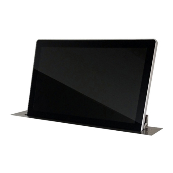
AH-AMMC: auto mechanical calibration movement system and the use of the Arthur Holm’s ERT will enable the address configuration of all the monitors installed in a table by simply pressing a button. The AHlink app allows a wireless access to the test and adjustment functions without removing the unit from the table. - Page 8 SYSTEM DESCRIPTION Available Models MODEL DESCRIPTION HDCP compliant vertically retractable aluminium 10,1" Full HD monitor with 20 degrees of adjustable inclination. Solid aluminium monitor housing with 17 mm. of thickness featuring double sided anti reflective black edged glass. Allows its installation in a furniture opening AH10DB2 of a maximum width of 21 mm and the monitor housing is flush with the desk once in recessed position.
- Page 9 SYSTEM DESCRIPTION Options AH10DB2 AH17DB2 AH22DB2 TS10DB2 TS17DB2 TS22DB2 Projected capacitive Projected capacitive Projected capacitive multitouch screen multitouch screen multitouch screen CABDB2 (Min.10 units) CABDB2 (Min.10 units) CABDB2 (Min.10 units) Black anodised Black anodised Black anodised GFDB2 (Min.10 units) GFDB2 (Min.10 units) GFDB2 (Min.10 units) Gold finish Gold finish...
- Page 10 SYSTEM DESCRIPTION Box Contents Before the installation of your retractable monitor, please check the contents of the shipping box, it must contain the following items: • Monitor • Power cord • Remote control (1 per 5 monitors) • Power supply 100-2 40Vac, 50-60Hz. Output 12V •...
-
Page 11: Installation Instructions
Cutting, drilling, soldering, adding electrical and mechanical components can cause danger and should be avoided by all means. Not complying with these directions will result in a loss of the Arthur Holm warranty. Albiral Display Solutions S.L. shall not be held liable for any loss... - Page 12 INSTALLATION INSTRUCTIONS Mounting table brackets Mount the table brackets below the table using the holes indicated IN the corresponding Pattern Hole drawing. The screws (x6) are not supplied. The weight of the monitor is up to 25Kg / 55.16 Lbs. PAY ATTENTION THAT THE BRACKETS ARE MOUNTED IN THEIR CORRESPONING SIDE.
- Page 13 INSTALLATION INSTRUCTIONS Mounting the monitor brackets Mount the monitor brackets in their corresponding side using the supplied screws. Mount the vertical adjustment screws (2+2) on to the monitor bracket so that the tip of the screw is flushed with the upper side of the monitor bracket.
- Page 14 INSTALLATION INSTRUCTIONS Checking assembly View from below the table: View from above the monitor: Dimensions A and B in table brackets and in monitor brackets must be the same (+-1mm). If adjustment is necessary loosen 3+3 Table bracket screws, keeping always symmetry regarding to the monitor hole in the table.
- Page 15 INSTALLATION INSTRUCTIONS Hanging the monitor Mount 2+2 nuts on to both table brackets as indicated in the drawing. Hang the monitor above nuts.
- Page 16 INSTALLATION INSTRUCTIONS Centring the monitor Tighten each nut gradually until the monitor surface is levelled with the table surface. Air gap around the monitor have to be 2mm [0,08]. Otherwise the monitor could come in contact with the table while opening and be damaged.
- Page 17 INSTALLATION INSTRUCTIONS Fine centring of the monitor In case fine centring of the monitor is necessary: Veneer Guide The DB2V is prepared to be mounted from below the table with a Veneer finishing on the top of the monitor to match the table. The Veneer is not supplied.
- Page 18 INSTALLATION INSTRUCTIONS Veener The Veneer can be placed in three ways: Option V1: Veneer: The veneer thickness must be 4mm [0,15] and the copper cylinder will be leveled with table surface. Option V2: Veneer + Distance Plate: For Veneers Thickness of 1mm [0,04] or less. It will be necessary a Distance Plate to hide the touch button copper cylinder.
- Page 19 INSTALLATION INSTRUCTIONS Option V3: Veneer: The veneer thickness must be 5mm [0,19]. A mechanised blind hole will be necessary to hide the touch button copper cylinder.
- Page 20 INSTALLATION INSTRUCTIONS Option V1: - Double side tape or glue used can’t be thicker than 0,2-0,25mm [0.008 0.01] Check if the Veneer fits perfectly with the monitor. To join both parts correctly it is important that the two surfaces are touching each other in the whole length.
- Page 21 INSTALLATION INSTRUCTIONS Option 1 Cut-Out: Option V2: - Distance Plate material can’t be metallic. Wood or DM are advisable. - Veneer material can’t be conductor. Check if the Distance Plate fits perfectly with the monitor. The copper cylinder can’t project outwards from the Distance Plate surface. To make easier the adjustment the height of the copper cylinder can be barely adjusted.
- Page 22 INSTALLATION INSTRUCTIONS 4. Clean the top surface of the Distance Plate and the bottom surface of the Veneer. Glue the Veneer. Double side tape or glue can be used (depending on the kind of materials are going to be The total thickness of Veneer + glue used can’t be thicker than 1mm [0.04].
- Page 23 INSTALLATION INSTRUCTIONS Option V3: - Veneer material can’t be conductor. Check if the Veneer fits perfectly with the monitor. To join both parts correctly it is important that the two surfaces are touching each other in the whole length. If there is a gap between the Veneer and the monitor, check if the hole depth in the Veneer is correct.
-
Page 24: Controls
CONTROLS IR sensor The IR sensor is located on the lower side of the screen. Monitor movement controls On the upper panel body, and on front glass, there is a button to control the down monitor movements, and the screen tilting angle. - Page 25 CONTROLS 1. Raising the monitor: Press the sensor located on the top of the monitor to raise the display. Make sure that no objects are located on top of the monitor. 2. Tilting the screen: Press and hold the sensor on the top of the monitor to adjust the desired tilt angle.
- Page 26 CONTROLS Remote control POWER Switch ON/OFF the monitor MENU Activates the OSD menu on screen Control up on the OSD menu DOWN Control down on the OSD menu LEFT Control left on the OSD menu RIGHT Control right on the OSD menu Selects the function on the OSD menu.
-
Page 27: Osd Menu
OSD MENU Accessing the menu system • With the OSD off, push the MENU button to activate the main OSD menu. • Press the UP and DOWN buttons to move from one function to another. Please refer to the following sections below to view a complete list of all the functions available for the monitor. - Page 28 OSD MENU Noise Reduction: Adjusts the image noise filter ∙ Off ∙ Low ∙ Medium ∙ High ∙ Default Screen: (Only for analogue signals) ∙ Auto Adjust ∙ Horizontal Position ∙ Vertical Position ∙ Size ∙ Phase Backlight: Adjusts the backlight screen's level Colour Range: Adjusts the colour range ∙...
- Page 29 OSD MENU Option Language: OSD language selection Restore Factory Default: Adjusts the parameters to the initial factory parameters Blending: OSD window transparency ∙ Low ∙ Medium ∙ High ∙ Off OSD Duration: Adjusts the time that the OSD menu window remains on the screen Software Update (USB): Port to use for firmware's upgrade.
-
Page 36: Input Connectors
INPUT CONNECTORS 12V D.C. Power supply input connector. XLR-4 connector. - 1,2: Ground - 3,4: 12Vdc GPI: Monitor external contact close control. SubD9 female. 1. GPI1 + 2. GPI1 – 3. GPI2 + 4. GPI2 – 5. GPI3 – 6. GPI3 + 7. -
Page 37: Ahnet Protocol
AHnet PROTOCOL Communications protocol COMMUNICATION RS422 CONNECTION RJ45 WIRING CAT-6 Speed and configuration BAUD RATE 38400 DATA BITS PARITY NONE STOP BITS Wiring Diagram 1. Data TX + 2. Data TX – 3. Data RX + 4. NC 5. NC 6 .Data RX –... - Page 38 AHnet PROTOCOL AHnet protocol Uses 5 bytes communication: BYTE 0 START BYTE BYTE 1 ADDRESS BYTE BYTE 2 COMMAND BYTE BYTE 3 VALUE 1 BYTE 4 VALUE 2 Commands COMMAND DESCRIPTION RESPONSE FA XX 01 01 00 GO UP FB XX 01 01 00 FA XX 01 00 00 GO DOWN FB XX 01 00 00...
- Page 39 AHnet PROTOCOL BITE CLOSED OPENED SCREEN ON SCREEN OFF DVI-A DVI 1-D DVI 2-D PROTECTION STOP MONITOR OK BITE BUTTON LOCK BUTTON UNLOCK...
- Page 40 AHnet PROTOCOL Picture Commands COMMAND DESCRIPTION RESPONSE FA XX 15 00 00 ASK FOR BACKLIGHT LEVEL FB XX 15 00 ZZ FA XX 16 00 00 ASK FOR CONTRAST LEVEL FB XX 16 00 ZZ FA XX 17 00 00 ASK FOR BRIGHTNESS LEVEL FB XX 17 00 ZZ Number of the monitor address.
-
Page 41: Video Signals
VIDEO SIGNALS RESOLUTION Horizontal freq (KHz) Vertical freq (Hz) Scanning type 800x600@60Hz 37.879 60.317 Progressive 800x600@72Hz 48.077 72.188 Progressive 800x600@75Hz 46.875 75.000 Progressive 1024x768@60Hz 48.363 60.005 Progressive 1024x768@70Hz 56.476 70.070 Progressive 1024x768@75Hz 60.023 75.030 Progressive 1280x720@60Hz 44.772 59.855 Progressive 1360x768@60Hz 47.720 59.799 Progressive... -
Page 42: Ahlink
AHLink AHlink is used to control and set-up the unit. By default, the AHLink wireless signal is deactivated. To activate it, please press and hold the Open and Close buttons simultaneously on the cover plate for 5 seconds. You can also activate the AHlink signal with the LCD (Interactive Setup Display) - Page 43 AHLink If your AH device does not appear on the screen, the AHLink signal might no longer be active. The AHLink name always begins with the characters “AH” followed by the four last MAC AHLink address. You must select the AH device. After selecting the AH device, the first page will upload on your screen.
- Page 44 AHlink SERIAL Serial number of the unit Firmware version Controls the Up and Down monitor movements DISP: Turns the display ON or OFF DVIA, DVI1, DVI2: Input source selection BACKL: Backlight adjustments CONTR: Contrast adjustments BRIGHT: Brightness adjustments SAVE VALUES: Memorises the backlight, contrast and brightness values AHLINK OFF: Turns off the AHlink signal COMMAND: Information of the last AHnet...
-
Page 45: Information On Disposal
INFORMATION ON DISPOSAL FOR USERS OF WASTE ELECTRICAL & ELECTRONIC EQUIPMENT This symbol on the products and/or accompanying documents means that used electrical and electronic products should not be mixed with general household waste. For proper treatment, recovery and recycling, please take these products to the designated collection points, where they will be accepted on a free of charge basis. -
Page 46: Warranty Terms And Conditions
WARRANTY TERMS AND CONDITIONS Albiral Display Solutions warrants this product against manufacturing defects and workmanship for a period of five (5) years from the date of purchase, subject to the conditions below. Mechanical parts: The engine and the product’s mechanical parts are warranted against manufacturing defects and workmanship for a period of five (5) years from the date of purchase. - Page 47 If you have any doubts concerning the terms of this warranty, please contact: business@albiral.com +34 938 502 376 Copyright © Nov. 2020. All rights reserved Albiral Display Solutions SL. Registered trademarks: Albiral, Arthur Holm...
- Page 48 Patents P27178ITEP P27178RUPC MU17180ES00 P27178USPC MU17301ES00 P27284DEEP MU17322ES00 P27284EPPC MU17413ES00 P27284ESEP MU17445ES00 P27284GBEP MU17854ES00 P27284RUPC MU17868DEPC P27284USPC MU17868RUPC P27715ESEP P24821DEEP P28089DEEP P24821ESEP P28089ESEP P24821GBEP Fàtima 25, Sant Hipòlit de Voltregà P28089ITEP P24821USPC 08512 Barcelona – Spain P28089USPC P27178DEEP tel: +34 93 850 23 76 / 23 83 P28090EP00 P27178EPDV01 fax: +34 93 850 25 50 / 23 72...
Need help?
Do you have a question about the DB2 Series and is the answer not in the manual?
Questions and answers