ARTHUR HOLM DynamicX2 AH15DX2HDGA User Manual
Hdcp compliant retractable monitors for furniture integration
Hide thumbs
Also See for DynamicX2 AH15DX2HDGA:
- User manual (26 pages) ,
- User manual (56 pages) ,
- User manual (37 pages)

Related Manuals for ARTHUR HOLM DynamicX2 AH15DX2HDGA


Summary of Contents for ARTHUR HOLM DynamicX2 AH15DX2HDGA
- Page 1 User Guide DynamicX2 HDCP compliant retractable monitors for furniture integration Technology Serving Design Danish craftmanship Mediterranean soul...
-
Page 2: Table Of Contents
TABLE OF CONTENTS REGULATIONS AND SECURITY SAFETY INSTRUCTIONS SYSTEM DESCRIPTION PACKING INSTRUCTIONS CONTROLS OSD MENU ISD MENU INPUT CONNECTORS AHnet PROTOCOL VIDEO SIGNALS AHLink INFORMATION ON DISPOSAL WARRANTY TERMS AND CONDITIONS... - Page 3 WELCOME Thank you very much for purchasing an Arthur Holm product. Please, read these installation and operating instructions carefully and keep them in a safe place for future consultations. We remain at your entire disposal if you have any suggestions.
- Page 4 ABOUT US The Company Arthur Holm has its origins in the Danish furniture designer Jorgen Alex Jensen, who was active during the sixties and the seventies. His design inspiration and his concept of ergonomics have been continued by his family, who is the design force behind Arthur Holm product range. The...
-
Page 5: Regulations And Security
REGULATIONS AND SECURITY ATTENTION: Do not disassemble or modify the device in any way. This symbol warns of the presence of dangerous un-insulated voltages inside some of the components, of sufficient magnitude to expose people to risk of electronic shock. This symbol draws attention to important use and maintenance instructions in the manual that accompanies the unit. - Page 6 SAFETY INSTRUCTIONS Wiring connected to hazardous voltage requires installation by qualified personnel or the use of ready-made flexible cables. For your security, your equipment must be connected to an electrical outlet with grounding connection protection. Since the plug is used to disconnect the device, the operating electrical outlet must be in an easily accessible place.
-
Page 7: System Description
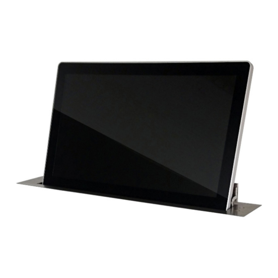
Monitors provide RS-422 I/O for the remote control of movement, speed, safety settings, brightness, contrast and backlight. They are also equipped with AH-AMMC. The use of the Arthur Holm’s ERT will enable the address configuration of all the monitors installed by simply pressing a button. - Page 8 SYSTEM DESCRIPTION Available Models MODEL DESCRIPTION HDCP compliant vertically retractable aluminium 15,6" Full HD monitor with 20 degrees of automatic inclination. Single engine patented mechanism. Solid aluminium monitor in natural anodisation finish featuring 3 mm. double sided anti reflective black edged glass. Up-table cover plate made of brushed stainless steel with 2 push buttons.
- Page 9 SYSTEM DESCRIPTION Available Models MODEL DESCRIPTION HDCP compliant vertically retractable aluminium 21,5" Full HD monitor with 20 degrees of automatic inclination. Single engine patented mechanism. Solid aluminium monitor in natural anodisation finish featuring 3 mm. double sided anti reflective black edged glass. Up-table cover plate made of brushed stainless steel with 2 push buttons.
- Page 10 SYSTEM DESCRIPTION Options AH15DX2HDGA AH17DX2HDGA AH19DX2HDGA AH22DX216GA AH24DX24KGA CL (Min.5 units) CL (Min.5 units) CL (Min.5 units) CL (Min.5 units) CL (Min.5 units) Laser engraved Laser engraved Laser engraved Laser engraved Laser engraved logo logo logo logo logo UCS (Min.10 units) UCS (Min.10 units) UCS (Min.10 units) UCS (Min.10 units)
- Page 11 SYSTEM DESCRIPTION Options AH15DX2HDGA AH17DX2HDGA AH19DX2HDGA AH22DX216GA AH24DX24KGA AC Power outlet AC Power outlet AC Power outlet AC Power outlet AC Power outlet Audio mini-jack Audio mini-jack Audio mini-jack Audio mini-jack Audio mini-jack VGACP VGACP VGACP VGACP VGACP VGA passthrough VGA passthrough VGA passthrough VGA passthrough...
- Page 12 SYSTEM DESCRIPTION Box Contents Before the installation of your retractable monitor, please check the contents of the shipping box, it must contain the following items: • Monitor • Power cord • Remote control (1 per 5 monitors) • Power supply 100-2 40Vac, 50-60Hz. Output 12V •...
-
Page 13: Packing Instructions
PACKING INSTRUCTIONS... -
Page 14: Controls
CONTROLS IR sensor The IR sensor is located on the lower right side of the screen. Monitor movement controls On the upper cover plate, there are two buttons to control the UP and DOWN monitor movements. 1. UP BUTTON CONTROL 2. - Page 15 CONTROLS Remote control POWER Switch ON/OFF the monitor MENU Activates the OSD menu on screen Control up on the OSD menu DOWN Control down on the OSD menu LEFT Control left on the OSD menu RIGHT Control right on the OSD menu Selects the function on the OSD menu.
-
Page 16: Osd Menu
OSD MENU Accessing the menu system • With the OSD off, push the MENU button to activate the main OSD menu. • Press the UP and DOWN buttons to move from one function to another. Please refer to the following sections below to view a complete list of all the functions available for the monitor. - Page 17 OSD MENU Noise Reduction: Adjusts the image noise filter ∙ Off ∙ Low ∙ Medium ∙ High ∙ Default Screen: (Only for analogue signals) ∙ Auto Adjust ∙ Horizontal Position ∙ Vertical Position ∙ Size ∙ Phase Backlight: Adjusts the backlight screen's level Colour Range: Adjusts the colour range ∙...
- Page 18 OSD MENU Option Language: OSD language selection Restore Factory Default: Adjusts the parameters to the initial factory parameters Blending: OSD window transparency ∙ Low ∙ Medium ∙ High ∙ Off OSD Duration: Adjusts the time that the OSD menu window remains on the screen Software Update (USB): Port to use for firmware's upgrade.
-
Page 19: Isd Menu
ISD MENU The Interactive Setup Display is an LCD screen located at the monitor casing inside the desk that allows the setup and provides useful diagnose and historical data of the device. - To start using it - ∙ WELCOME DISPLAY & DATA : 1) Bootloader Version The display will show a Bootloader Version message (example: Bootl. - Page 20 ISD MENU 2) FirmWare Data that refers to the firmware version (FW) of the equipment (example: FW Ver = 1.32). If you wish to update the FW version, please contact us. 3) Serial Number Serial number of the device (example: serial number of the device = 02658748).
- Page 21 ISD MENU ∙ MENUS GENERAL INFORMATION 1) AHnet - Adress The address must be set from 1 to 60. 2) VIDEO INPUT SELECTION The device provides the following inputs: DVI1 = DVI-I (DVI-A and DVI1-D) DVI2= DVI-D (DVI-2D) This menu allows the selection of 1 of these 3 inputs. 3) MONITOR BRIGHTNESS Brightness level (0 –...
- Page 22 ISD MENU 5) MONITOR BACKLIGHT Backlight level (0 – 100). 6) POSITION It is a diagnostic option that informs about the position of the device. 7) SENSORS INFORMATION It is a diagnostic option that informs about the internal state of the sensors. 8) AHnet - INFORMATION This menu is useful for programing and diagnose.
- Page 23 ISD MENU 9) UNIT OPENS It is a diagnostic option that provides historical data. It is very useful to analyze how the device has been used during its lifecycle and it provides information about how many movements the device has done.
- Page 24 ISD MENU 13) AUTO ADJUST Auto Mechanical Movement Calibration (AH-AMMC). Protocol activation: the device will make a consecutive movements series that must not be interrupted. The system will calibrate the speed and protection thresholds. 14) AHLink Activates AHlink. FIRMWARE UPDATE To update the FW version.
-
Page 25: Input Connectors
INPUT CONNECTORS 12V D.C. Power supply input connector. XLR-4 connector. - 1,2: Ground - 3,4: 12Vdc GPI: Monitor external contact close control. SubD9 female. 1 . GPI1 + 2. GPI1 – 3. GPI2 + 4. GPI2 – 5. GPI3 – 6. -
Page 26: Ahnet Protocol
AHnet PROTOCOL Communications protocol COMMUNICATION RS422 CONNECTION RJ45 WIRING CAT-6 Speed and configuration BAUD RATE 38400 DATA BITS PARITY NONE STOP BITS Wiring Diagram 1. Data TX + 2. Data TX – 3. Data RX + 4. NC 5. NC 6 .Data RX –... - Page 27 AHnet PROTOCOL AHnet protocol Uses 5 bytes communication: BYTE 0 START BYTE BYTE 1 ADDRESS BYTE BYTE 2 COMMAND BYTE BYTE 3 VALUE 1 BYTE 4 VALUE 2 Commands COMMAND DESCRIPTION RESPONSE FA XX 01 01 00 GO UP FB XX 01 01 00 FA XX 01 00 00 GO DOWN FB XX 01 00 00...
- Page 28 AHnet PROTOCOL BITE CLOSED OPENED SCREEN ON SCREEN OFF DVI-A DVI 1-D DVI 2-D PROTECTION STOP MONITOR OK BITE BUTTON LOCK BUTTON UNLOCK...
- Page 29 AHnet PROTOCOL Picture Commands COMMAND DESCRIPTION RESPONSE FA XX 15 00 00 ASK FOR BACKLIGHT LEVEL FB XX 15 00 ZZ FA XX 16 00 00 ASK FOR CONTRAST LEVEL FB XX 16 00 ZZ FA XX 17 00 00 ASK FOR BRIGHTNESS LEVEL FB XX 17 00 ZZ Number of the monitor address.
-
Page 30: Video Signals
VIDEO SIGNALS AH15D X2HDGA/ AH17D X2HDGA / AH19D X2HDGA / AH22D X216GA RESOLUTION Horizontal freq (KHz) Vertical freq (Hz) Scanning type 800x600@60Hz 37.879 60.317 Progressive 800x600@72Hz 48.077 72.188 Progressive 800x600@75Hz 46.875 75.000 Progressive 1024x768@60Hz 48.363 60.005 Progressive 1024x768@70Hz 56.476 70.070 Progressive 1024x768@75Hz 60.023... -
Page 31: Ahlink
AHLink AHlink is used to control and set-up the unit. By default, the AHlink wireless signal is deactivated. To activate it, please press and hold the Open and Close buttons simultaneously on the cover plate for 5 seconds. You can also activate the AHlink signal with the LCD (Interactive Setup Display) located under the monitor. - Page 32 AHLink If your AH device does not appear screen, AHlink signal might no longer be active. The AHlink name always begins with characters “AH” followed by the four last MAC AHlink address. You must select the AH device. After selecting the AH device, the first page will upload on your screen.
- Page 33 AHLink SERIAL Serial number of the unit Firmware version Controls the Up and Down monitor movements DISP: Turns the display ON or OFF DVIA, DVI1, DVI2: Input source selection BACKL: Backlight adjustments CONTR: Contrast adjustments BRIGHT: Brightness adjustments SAVE VALUES: Memorises the backlight, contrast and brightness values AHLINK OFF: Turns off the AHlink signal COMMAND: Information of the last AHnet...
-
Page 34: Information On Disposal
INFORMATION ON DISPOSAL FOR USERS OF WASTE ELECTRICAL & ELECTRONIC EQUIPMENT This symbol on the products and/or accompanying documents means that used electrical and electronic products should not be mixed with general household waste. For proper treatment, recovery and recycling, please take these products to the designated collection points, where they will be accepted on a free of charge basis. -
Page 35: Warranty Terms And Conditions
WARRANTY TERMS AND CONDITIONS Albiral Display Solutions warrants this product against manufacturing defects and workmanship for a period of five (5) years from the date of purchase, subject to the conditions below. Mechanical parts: The engine and the product’s mechanical parts are warranted against manufacturing defects and workmanship for a period of five (5) years from the date of purchase. - Page 36 If you have any doubts concerning the terms of this warranty, please contact: business@albiral.com +34 938 502 376 Copyright © Nov. 2020. All rights reserved Albiral Display Solutions SL. Registered trademarks: Albiral, Arthur Holm...
- Page 37 Patents P27178ITEP P27178RUPC MU17180ES00 P27178USPC MU17301ES00 P27284DEEP MU17322ES00 P27284EPPC MU17413ES00 P27284ESEP MU17445ES00 P27284GBEP MU17854ES00 P27284RUPC MU17868DEPC P27284USPC MU17868RUPC P27715ESEP P24821DEEP P28089DEEP P24821ESEP P28089ESEP P24821GBEP Fàtima 25, Sant Hipòlit de Voltregà P28089ITEP P24821USPC 08512 Barcelona – Spain P28089USPC P27178DEEP tel: +34 93 850 23 76 / 23 83 P28090EP00 P27178EPDV01 fax: +34 93 850 25 50 / 23 72...
Need help?
Do you have a question about the DynamicX2 AH15DX2HDGA and is the answer not in the manual?
Questions and answers