
Related Manuals for ARTHUR HOLM DYNAMICX2


Summary of Contents for ARTHUR HOLM DYNAMICX2
- Page 1 User Guide DYNAMICX2 HDCP compliant retractable monitors for furniture integration...
-
Page 3: Table Of Contents
TABLE OF CONTENTS SYSTEM DESCRIPTION MONITOR CONTROLS OSD MENU MICROPHONE CONTROLS RETRACTABLE HDMI CONTROL CABLE COVER CONTROLS ISD MENU CONNECTORS MICROPHONE HANDLING REMOVING THE MICROPHONE CAMERA AHnet PROTOCOL VIDEO SIGNALS AHLINK TILT CONTROL HDSDI CAMERA CONFIGURATION HDSDI CAMERA SPECIFICATIONS... - Page 4 WELCOME Thank you for purchasing an ARTHUR HOLM product. Please, read these installation and operating instructions carefully and keep them in a safe place for future consultations We remain at your entire disposal if you have any suggestions. Henrik Holm General Manager hholm@albiral.com...
- Page 5 ABOUT US The Company Arthur Holm has its origins in the Danish furniture designer Jorgen Alex Jensen, who was active during the sixties and the seventies. His design inspiration and his concept of ergonomics have been continued by his family, who is the design force behind Arthur Holm product range. The...
- Page 6 REGULATIONS AND SECURITY ATTENTION: Do not disassemble or modify the device in any way. This symbol warns of the presence of dangerous un-insulated voltages inside some of the components, of sufficient magnitude to expose people to risk of electronic shock. This symbol draws attention to important use and maintenance instructions in the manual that accompanies the unit.
- Page 7 SAFETY INSTRUCTIONS Wiring connected to hazardous voltage requires installation by qualified personnel or the use of ready-made flexible cables. For your security, your equipment must be connected to an elec- trical outlet with grounding connection protection. Since the plug is used to disconnect the device, the operating electrical outlet must be in an easily accessible place.
-
Page 8: System Description
Monitors provide RS-422 I/O for the remote control of movement, speed, safety settings, brightness, contrast and backlight. They are also equipped with AH-AMMC. The use of the Arthur Holm’s ERT will enable the address configuration of all the monitors installed by simply pressing a button. - Page 9 SYSTEM DESCRIPTION Highlights • Patented single engine mechanism for up/down and tilt movements • Milled alumium housing with a contemporary design • Front double sided anti-reflecting 2 sides coating 3 mm black edged glass • AH-AMMC Auto mechanical movement calibration •...
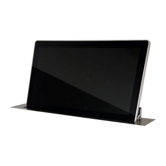
- Page 10 SYSTEM DESCRIPTION Available Models MODEL DESCRIPTION HDCP compliant vertically retractable aluminium 15.6" Full HD monitor with 20 AH15DX2HDGA degrees of automatic inclination. Single engine patented mechanism. Solid aluminium monitor in natural anodisation finish featuring 3 mm. double sided anti reflective black edged glass. Up-table cover plate made of brushed stainless steel with 2 push buttons.
- Page 11 SYSTEM DESCRIPTION Available Models MODEL DESCRIPTION AH22DX216GA HDCP compliant vertically retractable aluminium 21.5" Full HD monitor with 20 degrees of automatic inclination. Single engine patented mechanism. Solid aluminium monitor in natural anodisation finish featuring 3 mm. double sided anti reflective black edged glass. Up-table cover plate made of brushed stainless steel with 2 push buttons.
- Page 12 SYSTEM DESCRIPTION Options...
- Page 13 SYSTEM DESCRIPTION Options...
- Page 14 SYSTEM DESCRIPTION Options...
- Page 15 SYSTEM DESCRIPTION BOX CONTENTS Before the installation of your retractable monitor, please check the contents of the shipping box, it must contain the following items: • Monitor • Power cord • Remote control (1 per 5 monitors) • Power supply 100-2 40Vac, 50-60Hz. Output 12V •...
- Page 16 SYSTEM DESCRIPTION PACKING INSTRUCTIONS...
-
Page 17: Monitor Controls
MONITOR CONTROLS IR sensor The IR sensor is located on the lower right side of the screen. Monitor movement controls On the upper cover plate, there are two buttons to control the UP and DOWN monitor movements. 1. Raising the monitor: Press the button (1) on the right hand side of the cover plate to raise the monitor. - Page 18 MONITOR CONTROLS Remote control...
-
Page 19: Osd Menu
OSD MENU Accessing the menu system • With the OSD off, push the MENU button to activate the main OSD menu. • Press the UP and DOWN buttons to move from one function to another. Please reger to the following sections below to view a complete list of all the functions available for the monitor. - Page 20 OSD MENU Noise Reduction: Adjusts the image noise filter • Off. • Low. • Medium. • Hight • Default Screen: (Only for analogue signals) • Auto Adjust • Horizontal Position • Vertical Position • Size • Phase Backlight: Adjust the backlight screen's level Colour Range: Adjusts the colour range •...
- Page 21 OSD MENU Option Language: OSD language selection Restore Factory Default: Adjusts the parameters to the initial factory parameters. Blending: OSD window transparency • Low. • Medium. • High. • Off. OSD Duration: Adjusts the time that the OSD menu window remains on the screen.
-
Page 22: Microphone Controls
MICROPHONE CONTROLS On the upper cover plate, there are three buttons to control the functions and to external control other devices (GPO) • 1. UP/DOWN: Controls the elevation and retraction of the microphone lift. Press this button during 5 seconds to activate AHlink (5 beeps sounds when AHlink is activated). - Page 23 MICROPHONE CONTROLS • 3. TALK or GPO: The third push button has two different functions: - PA mode: In PA mode this button is used as MUTE function. Press the button once and the LED ring will appear in red indicating that the MUTE function is deactivated and it's ready for the user to talk to the audience.
-
Page 24: Retractable Hdmi Control Cable
RETRACTABLE HDMI CONTROL CABLE 1.Retractable HDMI cable EXTRACT/RETRACT control button... -
Page 25: Cover Controls
COVER CONTROLS Open hatch cover sensor control. On the cover, there is a touch sensor control button to open the hatch 1. Press cover open control button to open the cover monitor Screen UP control button Screen DOWN control button Hatch CLOSE control button... -
Page 26: Isd Menu
ISD MENU The Interactive Setup Display is an LCD screen located at the monitor casing inside the desk that allows the setup and provides useful diagnose and historical data of the device. ∙ WELCOME DISPLAY & DATA : 1) Bootloader Version The display will show a Bootloader Version message (example: Bootl). - Page 27 ISD MENU 2) FirmWare Data that refers to the firmware version (FW) of the equipment (example: FW Ver = 1.32). If you wish to update the FW version, please contact us. 3) Serial Number Serial number of the device (example: serial number of the device = 02658748).
- Page 28 ISD MENU The connection through RS422 allows the control of up to 30 devices perline. The last device (an only the last one) needs to have the termination activated. ∙ MENUS GENERAL INFORMATION 1) AHnet - Adress The address must be set from 1 to 60. ∙...
- Page 29 ISD MENU 5) MONITOR BACKLIGHT Backlight level (0 – 100). 6) POSITION It is a diagnostic option that informs about the position of the device. 7) SENSORS INFORMATION It is a diagnostic option that informs about the internal state of the sensors.
- Page 30 ISD MENU 9) UNIT OPENS It is a diagnostic option that provides historical data. It is very useful to analyze how the device has been used during its lifecycle and it provides information about how many movements the device has done. 10) UNIT STOPS It is a diagnostic option that provides historical data.
- Page 31 ISD MENU 13) AUTO ADJUST Auto Mechanical Movement Calibration (AH-AMMC). Protocol activation: the device will make a consecutive movements series that must not be interrupted. The system will calibrate the speed and protection thresholds. 14) AHLink Activates AHlink. FIRMWARE UPDATE To update the FW version.
-
Page 32: Connectors
CONNECTORS Power supply input connector. XLR-4 connector. - 1,2: Ground - 3,4: 12Vdc GPI: Monitor external contact close control. SubD9 female. 1. GPI1 + 2. GPI1 – 3. GPI2 + 4. GPI2 – 5. GPI3 – 6. GPI3 + 7. N.C. 8. - Page 33 CONNECTORS Microphone connectors GPI/GPO external contact close connector: 1. GND 2. Command microphone UP connecting to GND. Connecting to GND more than 2 seconds, activates the AHlink signal (5 beeps sounds when the AHLink signal is activated 3. Command microphone DOWN connecting to GND - Use a pulse signal to RISE and LOWER the microphone 4.
-
Page 34: Microphone Handling
MICROPHONE HANDLING Please follow the figure below for a correct product usage of the DynamicTalk microphones. To avoid any product malfunctions, do not attempt to bend the microphone to the incorrect angle or outside the microphone's working area, as indicated on the picture below. -
Page 35: Removing The Microphone
REMOVING THE MICROPHONE Removing the microphone with XLR connection Removing the microphone with a threaded connector... -
Page 36: Camera
CAMERA Below the unit, there are the camera connections In case that a USB camera is installed, there is a USB-A connector to connect the camera to a computer In case that a HDSDI camera is installed, there is a HDSDI BNC camera signal connector below the monitor... -
Page 37: Ahnet Protocol
AHnet protocol •Communication type : RS422 •Connection type : RJ45 •Wiring type : CAT-5 •Speed and configuration : – Baud Rate = 38400 – Data Bits = 8 – Parity = None – Stop Bits = 1 Wiring diagram 1-Data TX+ 2-Data TX- 3-Data RX+ 4-NC... - Page 38 AHnet protocol Using 5 bytes to communication: Screen control AHNet commands: XX: Number of the monitor address. Up to 30 monitors for each RS422 BUS CB1: Response in 8 bites of the monitor status CB2: Response in 8 bites of the monitor status...
- Page 39 Control BYTE answer control CB1: CB2:...
- Page 40 Picture commands XX: Number of the monitor address. Up to 30 monitors for each RS422 BUS ZZ: Level of the function selected (00 – 99 Dec) XX: Number of the monitor address. Up to 30 monitors for each RS422 BUS ZZ: Level of the function selected (00 –...
- Page 41 Picture commands TALK right side control AHNet commands: TALK left side control AHNet commands:: XX: Number of the monitor address. Up to 30 monitors for each RS422 To send an order to all units, you must use the address: 249 Dec. (Byte1) F9 Hex.
- Page 42 Picture commands CB1: Response in 8 bites of the monitor status CB2: Response in 8 bites of the monitor status Control BYTE answer control CB1: CB2: Not used...
- Page 43 Picture commands Retractable HDMI cable left side control AHNet commands: Retractable HDMI cable right side control AHNet commands: XX: Number of the monitor address. Up to 30 monitors for each RS422 To send an order to all units, you must use the address: 249 Dec.
-
Page 44: Video Signals
VIDEO SIGNALS... -
Page 45: Ahlink
AHlink AHlink is used to control and set-up the unit. By default, the AHLink wireless signal is deactivated. To activate it, please press and hold the Open and Close buttons simultaneously on the cover plate for 5 seconds. You can also activate the AHlink signal with the LCD (Interactive Setup Display) located under the monitor. - Page 46 AHlink If your AH device does not appear on the screen, the AHLink signal might no longer be active. The AHLink name always begins with the characters “AH” followed by the four last MAC AHLink address. You must select the AH device. After selecting the AH device, the first page will upload on your screen.
- Page 47 AHlink...
-
Page 48: Tilt Control
TILT CONTROL Use the screen up control button when the screen is in its working position (up), to adjust the position angle of the camera. Screen tilt (Camera) adjustment button: Press the screen up control button to control the screen tilt’s angle. Permanent press this button to tilt up the monitor up to 20˚... - Page 49 TILT CONTROL Use “4006” password AHLink APP, to access to unit settings...
- Page 50 AHlink On “Tilt Mode” configure the desired tilt mode: 110DEG: The screen tilts to maximum position (110º) NO TILT: The screen remains at 90º TIME: The screen tilt movement is active during a configurable periode of time You have to configure the “Tilt Time x 100mS” parameter, in case to configure “TIME”...
-
Page 51: Hdsdi Camera Configuration
HDSDI CAMERA CONFIGURATION Use AHLink APP to access to camera on screen menu settings, to configure the HDSDI camera. Press on “CAMERA” button to access to HDSDI camera control settings... - Page 52 HDSDI CAMERA CONFIGURATION Pressing MENU, use the HDSDI camera output signal below the monitor, to see the on screen menu and access to camera configuration Use the joystick AHLink APP buttons to set-up the camera properties. The set- up menu of the camera includes:...
- Page 53 HDSDI CAMERA CONFIGURATION...
- Page 54 HDSDI CAMERA CONFIGURATION...
-
Page 55: Hdsdi Camera Specifications
HDSDI CAMERA SPECIFICATIONS... - Page 56 Patents P27178ITEP P27178RUPC MU17180ES00 P27178USPC MU17301ES00 P27284DEEP MU17322ES00 P27284EPPC MU17413ES00 P27284ESEP MU17445ES00 P27284GBEP MU17854ES00 P27284RUPC MU17868DEPC P27284USPC MU17868RUPC P27715ESEP P24821DEEP P28089DEEP P24821ESEP P28089ESEP P24821GBEP Fàtima 25, Sant Hipòlit de Voltregà P28089ITEP P24821USPC 08512 Barcelona – Spain P28089USPC P27178DEEP tel: +34 93 850 23 76 / 23 83 P28090EP00 P27178EPDV01 fax: +34 93 850 25 50 / 23 72...
Need help?
Do you have a question about the DYNAMICX2 and is the answer not in the manual?
Questions and answers