Table of Contents
Advertisement
Quick Links
Advertisement
Table of Contents

Related Manuals for Rosslare AY-V64B


Summary of Contents for Rosslare AY-V64B
- Page 1 AY-V64B Multi-Reader Installation and Programming Manual...
- Page 2 ROSSLARE. ROSSLARE reserves the right to revise and change this document at any time, without being obliged to announce such revisions or changes beforehand or after the fact.
-
Page 3: Table Of Contents
Box Content ................7 Ancillary Equipment ..............7 Technical Specifications ..........8 Installation ..............9 The Installation Kit ..............9 Installing the AY-V64B ............9 Wiring Instructions ........... 11 Operation Instructions ..........12 Transmit Mode ..............12 Programming the AY-V64B............ 12 Entering Programming Mode .......... - Page 4 List of Figures List of Figures Figure 1: Removing the Top Cover ..............9 AY-V64B Installation and Programming Manual...
- Page 5 List of Tables List of Tables Table 1: Wiring Colors ..................11 Table 2: Programming Menus................13 Table 3: Keypad Transmission Format .............. 15 AY-V64B Installation and Programming Manual...
- Page 6 ROSSLARE exclusive warranty and liability is limited to the warranty and liability statement provided in an appendix at the end of this document.
-
Page 7: Introduction
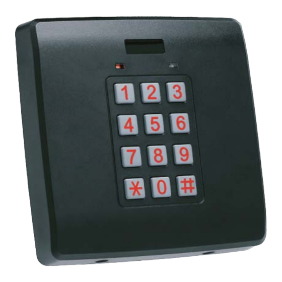
Introduction Introduction The AY-V64B is a programmable Wiegand and Clock & Data proximity card and keypad reader, which supports multiple proximity card and keypad formats to provide a high level of compatibility and connectivity with host controllers. The unit is programmable for proximity card data in 26-Bit Wiegand, Clock &... -
Page 8: Technical Specifications
125 x 125 x 21 mm (4.9 x 4.9 x 0.8 in.) Weight 285 g (10.1 oz) * Measured using a Rosslare proximity card or equivalent. Range also depends on electrical environment and proximity to metal. AY-V64B Installation and Programming Manual... -
Page 9: Installation
One L-shaped security screw tool Two security screws Installing the AY-V64B When installing the reader, you must remove the snap-off cover to access the screw holes (Figure 1). Figure 1: Removing the Top Cover AY-V64B Installation and Programming Manual... - Page 10 5. Route the interface cable from the reader to the controller. A linear type power supply is recommended. The reader can also be mounted using strong epoxy glue. After application, the reader should be firmly held in place until the glue dries. AY-V64B Installation and Programming Manual...
-
Page 11: Wiring Instructions
Wiring Instructions Wiring Instructions The AY-V64B is supplied with a 46-cm (18”) pigtail, comprising a 6- conductor cable. To connect the reader to the controller: 1. Prepare the reader cable by cutting the cable jacket back 3.2 cm (1¼”) and stripping the wire 1.3 cm (½”). -
Page 12: Operation Instructions
Operation Instructions Operation Instructions Transmit Mode When the AY-V64B is in Transmit mode, it is ready to receive data from a presented proximity card or an entered PIN code. Program Transmit When the reader is in Transmit mode, the Transmit LED is red and the Program LED is off When a proximity card or keyboard entry is being transmitted, the Transmit LED flashes green. -
Page 13: Entering Programming Mode
Menu Description Menu Number Selecting Keypad Transmission Format Single Key, Wiegand 6-Bit (Rosslare Format) Single Key, Wiegand 6-Bit with Nibble + Parity Bits Single Key, 8-Bit Wiegand, Nibbles Complemented 4 Keys Binary + Facility code, Wiegand 26-Bit 1 to 5 Keys + Facility code, Wiegand 26-Bit... -
Page 14: Exiting Programming Mode
The Program LED turns off and the Transmit LED turns red. This indicates that the AY-V64B has returned to Transmit mode. Wrong entries may reset the reader back to Transmit mode. While in Programming mode, if no key is pressed for 30 seconds, the AY-V64B exits Programming mode and returns to Transmit mode. -
Page 15: Keypad Transmission Format Option Number
More information on each of the different keypad transmission formats is available below and on the following pages. 5.5.1.1 S ingle Key, 6-Bit Wiegand (Rosslare Format) 2 1 B Each key press immediately sends 4 bits with 2 parity bits added; even parity for the first 3 bits and odd parity for the last 3 bits. - Page 16 000 to 255. The factory default setting for the Facility code is 000 (see Section 5.8). The keypad PIN code must be 4 digits long and can range between 0000 and 9999. On the fourth key press of the 4-digit PIN code, the AY-V64B Installation and Programming Manual...
- Page 17 4-digit keypad PIN code. If the entry of the 1 to 5 digit keypad PIN code is disrupted and no number key or " " key is pressed within 5 seconds, the keypad will AY-V64B Installation and Programming Manual...
- Page 18 V64B keypad while still keeping the proximity card readers 26-Bit Wiegand or Clock & Data formats active. An optional interface board must be used between the AY-V64B and the host system. Each key press is immediately sent on DATA0 as an ASCII character at a baud rate of 9600 bits per second.
- Page 19 If the entry of the digit keypad PIN code is disrupted and no number key or "#" key is pressed within 5 seconds, the keypad clears the PIN code entry buffer, generates a medium length beep and is ready to receive a new keypad PIN code. AY-V64B Installation and Programming Manual...
-
Page 20: Selecting Proximity Card Transmission Format
Operation Instructions Selecting Proximity Card Transmission Format The AY-V64B has two different selectable proximity card transmission formats. Follow the steps below to select the appropriate proximity card reader transmission format that you wish to use. To select the prox imity card transmission format:... -
Page 21: Changing The Programming Code
The AY-V64B output data turns into virtually 52-bit Wiegand, 26-bit Card data followed by a 26-bit keypad data After a card is presented to the AY-V64B, the Transmit LED starts to flash red indicating that reader is waiting for the PIN code. -
Page 22: Changing The Facility Code
To return to factory default settings: Transmit Program 1. Enter Programming mode. Green 2. Press "0" to enter Menu 0. The Transmit LED and the Program LED Transmit Program flash red. Red Red 3. Enter your 4-digit Programming code. AY-V64B Installation and Programming Manual... -
Page 23: Replacing A Lost Programming Code
5.10 Replacing a lost Programming Code In the event that the Programming code is forgotten, the AY-V64B may be reprogrammed in the field using the following instructions: 1. Remove power from the reader. 2. Activate tamper by removing the reader from the wall or removing the reader's case. -
Page 24: Limited Warranty
The full ROSSLARE Limited Warranty Statement is available in the Quick Links section on the ROSSLARE website at www.rosslaresecurity.com. Rosslare considers any use of this product as agreement to the Warranty Terms even if you do not review them. AY-V64B Installation and Programming Manual... - Page 25 +86 755 8610 6842 Fax: +86 755 8610 6101 Rosslare Security Products, Inc. support.cn@rosslaresecurity.com Southlake, TX, USA Toll Free: +1-866-632-1101 India Local: +1-817-305-0006 Rosslare Electronics India Pvt Ltd. Fax: +1-817-305-0069 Tel/Fax: +91-20-40147830 support.na@rosslaresecurity.com Mobile: +91-9975768824 Europe sales.in@rosslaresecurity.com Rosslare Israel Ltd.
Need help?
Do you have a question about the AY-V64B and is the answer not in the manual?
Questions and answers