Table of Contents

Related Manuals for GSS HDTV 1000 SPTS


Summary of Contents for GSS HDTV 1000 SPTS
- Page 1 Head-End HDTV Converter to IP DVB-S2 to SPTS HDTV 1000 SPTS CLASS Phone: +49 (0) 911 / 703 8877 Fax: +49 (0) 911 / 703 9210 Grundig SAT Systems GmbH E-mail: info@gss.de Beuthener Strasse 43 Internet: http://www.gss.de D-90471 Nuremberg...
-
Page 2: Table Of Contents
Testing the signal to noise ratio ..........22 Allocating the IP addresses ............23 Switching the IP address off or on ..........24 Transmission protocol ..............24 Port number ................24 Quantity of data packets ............25 Forward error correction ............25 - 2 - HDTV 1000 SPTS... - Page 3 DVB service information ............29 Output data rate ................30 Factory reset ................30 Saving settings ................31 Operation with a CA module ............32 PID monitoring ...............32 Configuring the CA module .............32 Descrambling services .............34 6 Final procedures ..................35 - 3 - HDTV 1000 SPTS...
-
Page 4: Safety Regulations And Notes
At the end of its service life, please take your device to one of these public collection facilities for proper disposal. - 4 - HDTV 1000 SPTS... -
Page 5: General Information
C o n t e n t s 1 Cassette HDTV 1000 SPTS 2 HF cables 1 Brief assembly instructions... - Page 6 LAN: ................1 RJ 45 socket ASI input: ..............1 BNC socket, 75 Ω ASI output: ..............1 BNC socket, 75 Ω Connection strip (10-pin): ....for supply voltages and control circuits RS 232 socket: ........serial interface for software update Conditional access:......several channels can be descrambled. - 6 - HDTV 1000 SPTS...
-
Page 7: Description
("C/N" menu). In an additional menu, the transmission of DVB service information (EIT, TDT and SDT) or teletext (TXT) can be individually activated or deactivated. EIT (Event Information Table): For each service, event information is transmitted (such as starting time, dura- tion, scrambling etc.) TDT (Time Date Table): The transmitted table contains the current time and date. - 7 - HDTV 1000 SPTS... -
Page 8: Software Query
If necessary, you can activate the indication of the software version of the control unit manually: • Press any two keys on the control unit of the head-end station simultaneously until the display goes dark and the software version, e.g. "V 44" appears. Cassette After activating the cassette the software version of the cassette is displayed (see page 16). - 8 - HDTV 1000 SPTS... -
Page 9: Assembly
• Insert the cassette in this slot and push it into the housing. • Align the cassette and apply slight pressure to connect it to the connections of the board and the HF bus bar. • Fasten the cassette with the screws 0° ACHTUNG! MESSAUSGANG Vor dem Cassettenwechsel unbedingt Netzstecker ziehen! CAUTION! Before changing cassettes remove mains plug! - 9 - HDTV 1000 SPTS... -
Page 10: Emc Regulations
19" cabinet. Tighten the nuts on the cable terminals until the teeth on the lock washer have pen- etrated the exterior coating and a good connection is made between the housing and cable terminals. - 10 - HDTV 1000 SPTS... -
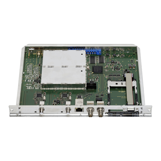
Page 11: Cassette Overview
—> In order to avoid restrictions of the network data rate (and therefore possible disturbances) we recommend to operate other applications like e.g. Internet, VOIP telephony etc. in separated networks. —> Exclusively use "Layer 3 switches", which support the IGMP protocol. • Connect the ASI input and the ASI output to the peripheral ASI devices. - 11 - HDTV 1000 SPTS... -
Page 12: Retrofitting A Ca Module
(top) of the CA module. • Insert the CA module into the guide rails of the CA slot with the top side of the CA module facing the top side of the cassette. • Push the CA module without canting into the guide rails of the CA slot and contact it to the common interface. - 12 - HDTV 1000 SPTS... -
Page 13: The Control Panel At A Glance
The key pad on the head-end station is used to scroll through the menus: scrolls forward through the menus. select parameters in the menus. set values, initiate actions. selects sub-menus. scrolls backward through the menus. saves all entries. - 13 - HDTV 1000 SPTS... -
Page 14: Programming
Kanalzug “A” mit CA-Modul Bx 1A only Channel strip “A“ with CA module on / off PID Check Bx 1A Menu <= => Edit - 14 - HDTV 1000 SPTS ◀ ▶ Bx 1A TV X 04/09 X / 0... - Page 15 TXT / txt, SDT / sdt EIT TDT TXT SDT (ON / off) copy Bx 4 DATARATE 72.956 Mbps page 14 Werkeinstellwerte Bx 4A FACTORY Bx 4A FACTORY aufrufen ▶ invoke factory defaults Defaults => STORE => M - 15 - HDTV 1000 SPTS...
-
Page 16: Programming The Cassette
• Select the cassette you want to program (e.g. Box 4) by repeatedly pressing the button if necessary. —> The display shows e.g. the menu "Box 4 DVBS2-SPTS": "Box 4" stands for slot 4 "DVBS2-SPTS" type of cassette "V 19" software version of the cassette - 16 - HDTV 1000 SPTS... -
Page 17: Ethernet Parameters
If "DHCP" is selected, the "IP-ADDR", "IP-MASK" and "IP-GATEWAY" sub-menus display the parameters that were assigned automati- cally by a connected server. If a server is not connected, " 0. 0. 0. 0*" appears in the corresponding menu. The star " * " in the display means that the data is provided by a DHCP server. Bx 4 IP-ADDR 192.168. 0.128 - 17 - HDTV 1000 SPTS... -
Page 18: Address Range
IP address displayed to be set and use to set the IP address wished. • Press the button. —> The "UDP port" – "UDP-PORT" menu is activated. - 18 - HDTV 1000 SPTS... -
Page 19: Udp Port
—> "OK" indicates that a transponder is received. If there is no input signal available "– –" is displayed instead of "OK". • Press the button. —> The "LNB oscillator frequency" – "LNB" menu is activated. - 19 - HDTV 1000 SPTS... -
Page 20: Lnb Oscillator Frequency
• To set other symbol rates use the buttons to position the cursor under the digit of the symbol rate displayed to be set. • Press to enter the respective digit of the symbol rate needed. • Repeat the procedure by the quantity of the digits to be set. - 20 - HDTV 1000 SPTS... -
Page 21: Input Frequency
1 MHz by varying the input frequency using the buttons. —> The "CN 12" display indicates the signal to noise ratio of the signal received. • Press the button. —> The "Testing the signal to noise ratio" – "C/N" menu is activated. - 21 - HDTV 1000 SPTS... -
Page 22: Testing The Signal To Noise Ratio
LED indicator Indication Green Signal quality is good Signal quality is insufficient Yellow No signal Status LED tuner B Status LED tuner A • Press the button to return to the main menu. • Press the button. - 22 - HDTV 1000 SPTS... -
Page 23: Allocating The Ip Addresses
"IP-OUT 16"). —> In the second line of the display the service is indicated allocated to the IP output (e.g. "Das Erste"). • Press the button. —> The "Switching the IP address off or on, Transmission protocol, Port number" – "MODE / PORT" menu is activated. - 23 - HDTV 1000 SPTS... -
Page 24: Switching The Ip Address Off Or On
• Using the buttons set the port number wished. Copying the settings to all IP addresses • Pressing the button the settings "transmission protocol" and "Port number" can be copied to all IP addresses. - 24 - HDTV 1000 SPTS... -
Page 25: Quantity Of Data Packets
FEC wished ("off, 10/9" … "20/19"). IP 1 PKTS / FEC 10/09 AnnexB Setting the transmission channel • Press the button to position the cursor under "Annex…". • Use the buttons to set the transmission channel wished ("AnnexA" / "AnnexB"). - 25 - HDTV 1000 SPTS... -
Page 26: Ip Addresses For Services
227. 40. 50. 60 Allocating IP addresses to services manually • Press the buttons to position the cursor under the digit of the IP ad- dress to be set. • Using the buttons set the IP address wished. - 26 - HDTV 1000 SPTS... -
Page 27: Allocating Services Manually
For radio stations, the background of the screen of the connected TV or test receiver is darkened. " * " The star means that the TV or radio station selected is scrambled. To enable the stations, the CA module and the appropriate smart card of the station pro- vider are required. - 27 - HDTV 1000 SPTS... -
Page 28: Sound Options Of The Service
IP 1 AUDIO • Press to select the desired sound option (e.g. "all", "deu" – German, "2ch" etc.). • Press the button. —> The "DVB service information" – "OPTIONS" menu is activated. - 28 - HDTV 1000 SPTS... -
Page 29: Dvb Service Information
—> The display shows "copy" for a short time. • Press the button. —> The "Allocating the IP addresses" – "IP-OUT …" menu is activated (page 23). • Repeat the settings until all services wished are allocated to an IP address. • Press the button. —> The "Output data rate" – "DATARATE" menu is activated. - 29 - HDTV 1000 SPTS... -
Page 30: Output Data Rate
—> The factory defaults are saved. The display shows "STORE" —> Back to "Selecting the cassette" (page 16). —> By pressing the button, you will be returned to the menu item "Ethernet parameters" without saving the factory defaults (page 17). - 30 - HDTV 1000 SPTS... -
Page 31: Saving Settings
• Press the button. —> Back to "Selecting the cassette" (page 16). —> The settings are saved. - 31 - HDTV 1000 SPTS... -
Page 32: Operation With A Ca Module
Bx 4A Menu <= => Edit Bx 4A 01/03 MENU Bx 4A TV Bx 4A TV 04/09 04/09 Information *) ..- 32 - HDTV 1000 SPTS... - Page 33 CA module and are returned to the "Configuring the CA module" – "CA" menu. • Press the button. —> The "Descrambling services" – "Edit" menu is activated. - 33 - HDTV 1000 SPTS...
-
Page 34: Descrambling Services
—> The filter is activated. The display shows the "Configuring the CA module" – "CA" menu. Bx 4A Menu <= => Edit • Press the button. —> The "Input data stream" – "INPUT" menu is activated (page 19). - 34 - HDTV 1000 SPTS... -
Page 35: Final Procedures
After installing the head-end station, upgrading accessories or installing cas- settes it is necessary to tighten all cable connections, cable terminals and cover screws in order to maintain compliance with current EMC regulations securely. • Securely tighten the cable bolted connections using an appropriate open- ended spanner. • Mount the front cover (see assembly instructions of the head-end station). - 35 - HDTV 1000 SPTS... - Page 36 Declaration of CE conformity - 36 - HDTV 1000 SPTS...
- Page 37 Service: Phone: +49 (0) 911 / 703 2221 Fax: +49 (0) 911 / 703 2326 Email: service@gss.de Alterations reserved. Technical data E. & O.E. © by GSS GmbH V19/26072011...
Need help?
Do you have a question about the HDTV 1000 SPTS and is the answer not in the manual?
Questions and answers