Table of Contents
Advertisement
Quick Links
Advertisement
Table of Contents

Related Manuals for GSS HDE 400


Summary of Contents for GSS HDE 400
- Page 1 HDE 400...
-
Page 2: Table Of Contents
o n t e n t s 1 Safety regulations and notes ................ 4 2 General information ..................5 Packing contents ................5 Meaning of the symbols used ............5 Technical data ................5 Description ...................7 Signal runtime ................8 Software versions ................9 Block diagram ................9 3 Assembly ....................10 Installing the cassette..............10 EMC regulations ................11 Cassette overview................12... - Page 3 COFDM output signal ............... 30 Transmission parameters ............31 Transmitter identification ............32 Substitute signal in the case of an incorrect input signal ....33 Ethernet parameters ..............33 IP address of the cassette ............34 Address range (subnet mask) ...........34 Address of the gateway ............35 UDP port ................35 IP output signal ................36 Setting the output data rate ............36...
-
Page 4: Safety Regulations And Notes
a f e t y r e g u l a t i o n s a n d n o t e s • Assembly, installation and servicing should be carried out by authorised electricians. • Switch off the operating voltage of the system before beginning with assem- bly or service work or pull out the mains plug. -
Page 5: General Information
2.1 P aC k i n g C o n t e n t s 1 Cassette HDE 400 1 Brief assembly instructions 2.2 m e a n i n g... - Page 6 MPEG4 Encoder Transport stream ........H.264/AVC High Profile Level 4.0 Setting range of total data rate (video + audio + tables) ... 1 Mbit/s…30 Mbit/s Video data rate: 1920x1080p ............6 Mbit/s…30 Mbit/s 1920x1080i ............6 Mbit/s…24 Mbit/s 1280x720p ............4 Mbit/s…24 Mbit/s 720x576i ...............
-
Page 7: Description
Connections Video Inputs: HDTV ............1 HDMI 1.4a (typ A, 19 Pin) Component YPbPr ............3 Cinch sockets CVBS ................1 Cinch socket Audio Inputs: PCM ................. 1 HDMI 1.4a S/PDIF (PCM) .................1 TOSLINK Analogous Stereo ............2 Cinch sockets LAN ................. 1 RJ 45 socket ASI input ..............1 BNC socket, 75 Ω... -
Page 8: Signal Runtime
The MPEG4 encoder generates a transport stream according to H.264/AVC (Advanced Video Coding) High Profile Level 4.0 standard. At the LAN socket one SPTS/MPTS transport stream (Single/Multi Programme Transport stream, adjustable data rate) according to UDP or RTP protocol can be output. -
Page 9: Software Versions
o f t wa r e v e rs i o n s Cassette After activating the cassette the software version of the cassette is displayed (see page 18). Control unit To operate these cassettes the software version of the control unit must be "V45"... -
Page 10: Assembly
s s e m b l y 3.1 i n s ta l l i n g t h e C a s s e t t e – Ensure the head-end station is mounted so it will not be able to vibrate. Avoid, for example, mounting the head-end station onto a lift shaft or any other wall or floor construction that vibrates in a similar way. -
Page 11: Emc Regulations
3.2 emC r e g u l at i o n s To comply with the current EMC regulations, it is necessary to connect the lines leading in and out of the head-end station using cable terminals. When mounting the cassette in a head-end station which is installed in a 19" cabinet, make sure the connections leading in and out for the 19" cabinet are made using cable terminals. The attenuation of shielding of the connection lines for ASI and antenna must meet the requirements for "Class A". CLASS • Insert the required number of cable terminals in the openings provided in the head-end station or in the 19" cabinet. Tighten the nuts on the cable terminals until the teeth on the lock washer have penetrated the exterior coating and a good connection is made between the hous- ing and cable terminals. -
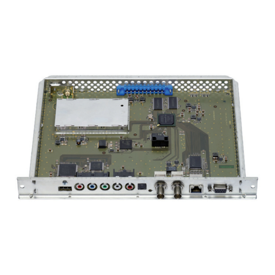
Page 12: Cassette Overview
3.3 C a s s e t t e ov e rv i e w D-SUB socket "RS 232" Status LED network LAN socket Status LED data transfer ASI output ASI input Status LED ASI input OPTICAL S/PDIF PCM audio input TOSLINK Audio input R analogous Audio input L analogous Video input Y/CVBS... -
Page 13: Updating The Software
3.5 u P dat i n g t h e s o f t wa r e The RS 232 interface of the cassette enables you to use a PC or a notebook and the "BE-Flash" software to update the software of the cassette. You can find the "BE-Flash"... -
Page 14: The Control Panel At A Glance
C o n t r o l P a n e l g l a n C e 4.1 m e n u i t e m s Program the cassette using the buttons on the control unit of the head-end sta- tion. -
Page 15: Programming
r o g r a m m i n g 5.1 P r o g r a m m i n g P r o C e d u r e BE–Remote V 45 Ein/On Bedienhinweise please wait … "blättert" Menüs vorwärts. "blättert"... - Page 16 Bx 2 LEVEL Bx 2 - 6 dB => OFF/QAM/COFDM Bx 2 FREQ 858.00 MHz COFDM Bx 2 Bx 2 COFDM 6900 QAM 256 POS 8MHZ QAM64 Bx 2 FAILURE Bx 2 COFDM Tables C7/8 G1/32 Bx 2 CELL-ID 0x0000 Bx 2 FAILURE Tables...
- Page 17 1234 /RTP IP 1 PKTS/FEC 1…7 / 10/09 AnnexB / … / 20/19 AnnexB IP 1 OUT-IP 227. 40. 50. 60 nur wenn IP-Adresse außerhalb des Bx 4 DEST-MAC ◀ ▶ Multicastbereichs liegt 0022B7000000 –> Unicastverbindung only if IP address is out of multicast range –>...
-
Page 18: Programming The Cassette
5.2 P r o g r a m m i n g t h e C a s s e t t e —> Pressing the button for longer than 2 seconds cancels the programming procedure. This takes you back to the programme item "Selecting the cassette"... -
Page 19: Encoder
n C o d e r Via this menu you get access to the submenus in order to do the encoder set- tings and to select the desired input. —> If no encoder settings should be done, press button The "RF output" – "RF" main menu is activated (page 23). •... -
Page 20: Total Data Rate
• Press the button. —> The "Total data rate" – "BITRATE" submenu is activated. ota l data r at e In this menu you set the total data rate (video + audio + tables), with which the input signal shall be encoded. Bx 2 BITRATE 10.0 Mbps... -
Page 21: Video Signal Type/Input
– "1080i/50": A maximum HDMI video format of 1080i/50Hz will be communicated to the source player. – "720p/50": A maximum HDMI video format of 720p/50Hz will be communicated to the source player. • Press the button. —> The "Video signal type/input" – "INPUT" submenu is activated. i d e o s i g n a l t y P e... -
Page 22: Audio Input / Audio Level
IPPP - minor compression – HDTV at high data rate for "fast conver- sion" at short channel switching delay. —> At a resolution of 1080p the setting "IPPP" is not available. • Press the button. —> The "Audio input/Audio level" – "AUDIO-IN" submenu is activated. / a u d i o i n P u t... -
Page 23: Audio Data Rate
u d i o data r at e In this menu you set the data rate with which the audio signal shall be en- coded. Bx 2 AUDIO 192 kbps Stereo • Use the buttons to enter the desired audio data rate. —>... -
Page 24: Kind Of Modulation
—> If, despite activated RF output, the encoded input signal is not out- put, the bypass function of the ASI input my be active (page 42). • Press the button. —> The "Ethernet parameter" – "ETHERNET" main menu is activated (page 33). -
Page 25: Channel / Frequency
—> The "Channel / Frequency" – "FREQ" submenu is activated. / f h a n n e l r e q u e n C y In this menu you adjust the output channel or the output frequency of the modu- lator. -
Page 26: Output Symbol Rate, Qam Modulation
, qam u t P u t s ym b o l r at e m o d u l at i o n —> This menu is only displayed if "QAM modulation" is selected in menu "RF output" (page 23)! In this menu you can set the output symbole rate, the QAM modulation and invert the user signal. -
Page 27: Cofdm Parameters
Cofdm Pa r a m e t e rs —> This parameters must only be observed if "COFDM modulation" is selected in menu "RF output" (page 23)! If "QAM modulation" is selected please continue with submenu "Sub- stitute signal in the case of an incorrect input signal" – "FAILURE" (Page 33). - Page 28 If the bandwidth is decreased by 1 MHz the transmittable data rate is de- creased by approx. Net data rate [kbit/s] at a bandwidth of 7 MHz Guard interval Modulation Code rate 4354 4838 5123 5278 5806 6451 6830 7037 QPSK 6532 7257 7684 7917 7257 8064 8538 8797 7620 8467 8965 9237...
- Page 29 Transmission parameters for DVB-T at a bandwidth of 8 MHz Transmission mode Symbol duration T [µs] Carrier space ∆ f [kHz] 4.4643 2.232 1.116 2048 4096 8192 carrier theoretical 1705 3410 6817 carrier real Used bandwidth [MHz] 7.61 7.61 7.61 Total symbol duration 280 262 238 231 560 504 476 462 1120 1008 952 924 [µs] Guard interval T [µs]...
-
Page 30: Cofdm Output Signal
Cofdm o u t P u t s i g n a l —> This menu is only be displayed if "COFDM modulation" is selected in menu "RF output" (page 23)! If "QAM modulation" is selected please continue with submenu "Sub- stitute signal in the case of an incorrect input signal"... -
Page 31: Transmission Parameters
—> The "Transmission parameters" – "COFDM-MODE" submenu is acti- vated. r a n s m i s s i o n Pa r a m e t e rs —> This menu is only be displayed if "COFDM modulation" is selected in menu "RF output"... -
Page 32: Transmitter Identification
• Set the guard interval required using the buttons ("G1/4", "G1/8", "G1/16", "G1/32"). • Press the button. —> The "Transmitter identification" – "COFDM TPS" menu is activated. r a n s m i t t e r i d e n t i f i C at i o n —>... -
Page 33: Substitute Signal In The Case Of An Incorrect Input Signal
u b s t i t u t e s i g n a l t h e C a s e i n C o r r e C t i n P u t s i g n a l You use this menu to set whether a COFDM signal filled with null packets and self-made tables "Tables"... -
Page 34: Ip Address Of The Cassette
• Press the buttons to select … – manual setting ("stat") of the Ethernet parameter, – automatic setting ("DHCP") of the Ethernet parameter or – to deaktivate Ethernet ("off"). • Press the button to activate the setting options ("Options"). —> The "IP address of the cassette" – "IP-ADDR" submenu is activated. a d d r es s t h e C a s s e t t e... -
Page 35: Address Of The Gateway
—> The "Address of the gateway" – "IP-GATEWAY" submenu is activated d d r es s t h e gat e way The address of a gateway (server) can be set in this menu. If no gateway is used you can skip this setting. Bx 2 IP-GATEWAY 192.168. -
Page 36: Setting The Output Data Rate
o u t P u t s i g n a l Herein you get access to the submenus for IP output settings. —> If no IP output settings should be done, press button The "ASI output" – "OUTPUT ASI" main menu is activated (page 42). Bx 2 OUTPUT =>... -
Page 37: Transmission Protocol / Port Number
—> The "Transmission protocol / Port number" – "MODE / PORT" sub- menu is activated. / P r a n s m i s s i o n P r oto C o l o r t n u m b e r In this menu you can define the transmission protocol and the port number. -
Page 38: Quantity Of Data Packets
ua n t i t y data PaC k e t s / t o rwa r d e r r o r C o r r e C t i o n r a n s m i s s i o n C h a n n e l In this menu you set the quantity of the data packets to be transmitted, the for- ward error correction FEC and the transmission channel. -
Page 39: Ip Output Signal
iP u t P u t a d d r es s u lt i C a s t n i C a s t In this menu you set the output IP address for the selected transport stream. IP 1 OUT-IP 227. -
Page 40: Asi Output
• Press the button. —> Return to the main menu "IP output signal" • Press the button. —> The "ASI output" – "OUTPUT ASI" main menu is activated. asi o u t P u t Herein you get access to the submenus for ASI output settings. —>... -
Page 41: Asi Options
asi o P t i o n s In this menu you define the size of the data packets, their polarity and the type of transmission. For this setting please take the required information from the documentation (technical data) of the ASI component to be connected. Bx 2 ASI OPTION 188 pos. -
Page 42: Asi Input Station Filter; Bypass Asi => Rf
asi i asi => rf n P u t s tat i o n f i lt e r y Pa s s Herein you get access to the submenus for ASI input filter settings. —> If no ASI input filter settings should be done, press button The "Output data rate"... - Page 43 —> The display shows e.g.: Bx 2 01/04 Das Erste Meaning of the indicators in the example: "TV" "Television" (type of service) " " The currently selected service is passed through "01/04" The 1st of 4 services is being displayed. "Das Erste" Name of the service Further possible terms displayed: "ASI"...
-
Page 44: Output Data Rate
u t P u t data r at e Herein the current needed and the maximum data rate is displayed. Bx 2 DATARATE 38.3/ 50.9 Mb —> The maximum data rate is dependent on the settings of the modula- tor and the ASI data rate. As the output data stream is present at all outputs, the lowermost set output data rate is used for the maximum value. -
Page 45: Transport Stream Id And Orgnet Id
id orgnet id r a n s P o r t s t r e a m a n d If the input signals are encoded to a separate transport stream (if no transport stream with ORGNET-ID is present at the ASI input), a new ORGNET-ID must be assigned to the transport stream. -
Page 46: Factory Reset / Soft Reset
• To switch off the new NIT ("off") press the button. —> The NITs of the other "NIT cassettes" will stay switched on. When the NIT of the cassette is switched on again ("on") by pressing the button, the previously generated NIT is added again. If you have changed parameters in the meantime, you must first select "Make"... -
Page 47: Soft Reset
—> The cassette is reset to factory defaults. The display shows "STORE" —> Back to "Selecting the cassette" (page 18). • In order to perform a soft reset (cassette restart) or to return to the main menu "Factory Default" press the button. -
Page 48: Final Procedures
i n a l P r o C e d u r e s After installing the head-end station, upgrading accessories or installing cas- settes it is necessary to tighten all cable connections, cable terminals and cover screws in order to maintain compliance with current EMC regulations securely. • Securely tighten the cable bolted connections using an appropriate open- ended spanner. • Mount the front cover (see assembly instructions of the head-end station). - 48 - HDE 400... -
Page 49: Channel And Frequency Tables
h a n n e l a n d f r e q u e n C y t a b l e s Advice for a frequency grid (8 MHz) in the Band I/III 42.00 82.00 146.00 186.00 226.00 266.00 50.00 114.00... - Page 50 Declaration of CE conformity GSS Grundig SAT Systems GmbH • Beuthener Straße 43 • D-90471 Nuremberg Phone: +49 (0) 911 / 703 8877 • Fax: +49 (0) 911 / 703 9210 www.gss.de/en • info@gss.de CLASS CLASS Service: Phone: +49 (0) 911/703 2221; Fax: +49 (0) 911/703 2326; service@gss.de Alterations reserved.
Need help?
Do you have a question about the HDE 400 and is the answer not in the manual?
Questions and answers