Advertisement
Quick Links
Advertisement

Related Manuals for GSS HDM 400 P CI


Summary of Contents for GSS HDM 400 P CI
- Page 1 HDM 400 P CI...
- Page 2 o n t e n t s 1 Safety regulations and notes ................ 4 2 General information ..................5 Packing contents ................5 Meaning of the symbols used ............5 Technical data ................5 Description ...................6 Block diagram ................6 General ..................7 Software query................7 3 Assembly ....................8 Installing the cassette..............8 EMC regulations ................9 Cassette overview................10 Connecting the cassette ..............10...
- Page 3 Station Selection ................23 Selecting the TV station sound / volume level ........24 Selecting the TV station sound ..........24 Setting the volume level ............24 Audio mode / Audio output ............25 Setting the audio mode ............25 Setting the audio output ............25 Picture format ................25 WSS (wide screen signalling) / Teletext mode ......26 Switching WSS (wide screen signalling) off/on ......26 Switching teletext mode off/on ..........26...
- Page 4 a f e t y r e g u l a t i o n s a n d n o t e s • Assembly, installation and servicing should be carried out by authorised electricians. • Switch off the operating voltage of the system before beginning with assem- bly or service work or pull out the mains plug.
- Page 5 2.1 P aC k i n g C o n t e n t s 1 Cassette HDM 400 P CI 1 RF cable 1 Brief assembly instructions 2.2 m...
- Page 6 RF output Frequency range: ........... 42.0 MHz … 783.25 MHz Channels: ................C02 … C60 Output level: ................103 dBμV Output impedance: ................. 75 Ω Connections RF input: ................1 F sockets RF output: ................1 IEC socket Connection strip (10-pin): ....for supply voltages and control circuits RS-232 socket: ........
- Page 7 e n e r a l As signal source the corresponding Tuner can be selected. Using an adequate CA module a scrambled channel can be descrambled. A LED provide an indication of the input signal quality based on their colour (see figure on page 10).
- Page 8 s s e m b l y 3.1 i n s ta l l i n g t h e C a s s e t t e – Ensure the head-end station is mounted so it will not be able to vibrate. Avoid, for example, mounting the head-end station onto a lift shaft or any other wall or floor construction that vibrates in a similar way.
- Page 9 3.2 emC r e g u l at i o n s To comply with the current EMC regulations, it is necessary to connect the lines leading in and out of the head-end station using cable terminals. When mounting the cassette in a head-end station which is installed in a 19" cabinet, make sure the connections leading in and out for the 19" cabinet are made using cable terminals. The attenuation of shielding of the connection lines for ASI and antenna must meet the requirements for "Class A". CLASS • Insert the required number of cable terminals in the openings provided in the head-end station or in the 19" cabinet. Tighten the nuts on the cable terminals until the teeth on the lock washer have penetrated the exterior coating and a good connection is made between the hous- ing and cable terminals.
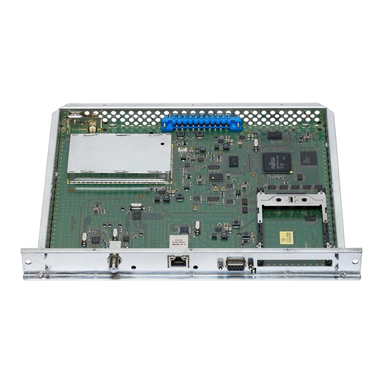
- Page 10 3.3 C a s s e t t e ov e rv i e w Slot for CA module D-SUB socket "RS 232" not used Status LED RF input The operating software of the cassette can be updated via the 9-pin D-SUB socket "RS 232"...
- Page 11 3.5 r Ca e t r o f i t t i n g m o d u l e The cassette is equipped with a common interface. It allows you to connect a CA module for various scrambling systems and service providers. Scrambled channels can only be descrambled with a CA module suitable for the scram- bling system and the corresponding smart card.
- Page 12 C o n t r o l P a n e l g l a n C e 4.1 m e n u i t e m s Programme the cassette using the buttons on the control unit of the head-end station.
- Page 13 r o g r a m m i n g 5.1 P r e Pa r at i o n • Test the software versions of the head-end station and the cassette and up- date them if necessary. The current software versions can be found on the website "www.mygss.eu". 5.2 n ot es l e v e l...
- Page 14 5.3 P ro g r a m m i n g Pro C e d u r e Ein / On Bedienhinweise Operating Hints BE–Remote V 45 "blättert" Menüs vorwärts. scrolls forward through the menu. please wait … "blättert" Menüs rückwärts. scrolls backward through the menu.
- Page 15 ◀ ▶ 474.00 MHz Bx 4 INPUT QAM256 COFDM 7/8MHZ QAM 16…256 Bx 4 01/06 Das Erste Bx 4 AUDIO ◀ ▶ 01/03 - 6 dB + 6 … - 26 dB Bx 4 AUDIO ◀ ▶ auto DUAL norm normal / swap auto/stereo/dual Bx 4...
- Page 16 5.4 P r o g r a m m i n g t h e C a s s e t t e —> Pressing the button for longer than 2 seconds cancels the programming procedure. This takes you back to the programme item "Selecting the cassette"...
- Page 17 e l e C t i n g t h e C a s s e t t e Box … …… ……… …… Bx 1A TWIN-SAT Böx 4 TWIN-SAT Box 4 HD-PAL Box 5 ....C5-12,S3-24 C5-12,S3-24 – – – ....
- Page 18 u t P u t Pa r a m e t e r In this menu you adjust the output channel or the output frequency of the modu- lator. h a n n e l s e t t i n g Bx 4 OUTPUT 783.25 MHz...
- Page 19 • Use button to select the desired signal source (tuner or ASI). • Press the button. If CABLE/TERR is selected: —> Input parameter DVB-C/T The "Remote power supply" – "POWER" submenu is activated (page 22). If SAT is selected: —> Input parameter SAT The "LNB oscillator frequency"...
- Page 20 , dvb n P u t s ym b o l r at e m o d e In this menu set the symbol rate of the desired transponder. —> This menu is only displayed if "SAT" is selected for the input signal source.
- Page 21 Once the RF receiver has synchronised to the input signal, any offset to the target frequency is displayed in MHz, e.g. "– 1.8". If a question mark "?" appears in the second line of the display, there is no input signal present. In this case check the configuration of the antenna system and head-end station as well as the preceding settings of the cassette.
- Page 22 dvb-C/t n P u t Pa r a m e t e r dvb-t e m ot e P ow e r s u P P ly o n ly n e e d e d r e C e P t i o n In this menu you can switch on or off a 5V (max.
- Page 23 / s i n d m o d u l at i o n ym b o l r at e In this menu you have to set the kind of modulation for the transponder to be received. Bx 4 INPUT QAM256 •...
- Page 24 Further possible terms displayed: "RA" Radio channel type For radio stations, the background of the screen of the connected TV or test receiver is darkened. " * " The star means that the TV or radio station selected is encoded. To enable the stations, the CA module and the appropriate smart card of the station provider are required.
- Page 25 • Press the button. —> The "Audio mode / Audio output" – "AUDIO auto / Dual …" menu is activated. / a u d i o m o d e u d i o o u t P u t In this menu you can define whether the Stereo or Dual Tone signal from the MPEG data stream is to be used.
- Page 26 "Letterbox": Black bars at the top and bottom edge of the screen (so that the picture is not distorted at 4:3 TVs). "16:9": In the case of TVs with the picture format 4:3, the picture con- tent is vertically "stretched" (e.g. faces appear longer). •...
- Page 27 o n d i t i o n a l aCC es s In this menu you can call up a menu for the settings of the CA module (depend- ent on the CA module). Bx 4 MENU => —> If there is no CA module is inserted, this menu is out of order. Indication: Bx 4 MENU...
- Page 28 —> By pressing the button you can cancel the settings in the menu of the CA module and are returned to the "Conditional Ac- cess" – "CA" menu. • All settings are saved by pressing the button. —> You will be returned to the "Conditional Access" – "CA" menu. •...
- Page 29 • Press the button. —> The "Factory reset" – "FACTORY Defaults" menu is activated. aC to ry r es e t In this menu you can reset all settings to the factory defaults. Bx 4 FACTORY Bx 4 FACTORY ▶ Defaults =>...
- Page 30 av i n g s e t t i n gs • Press the button. —> Returning to "Selecting the cassette" menu (page 17). —> The settings are saved. i n a l Pro C e d u res After installing the head-end station, upgrading accessories or installing cas- settes it is necessary to tighten all cable connections, cable terminals and cover screws in order to maintain compliance with current EMC regulations securely.
- Page 31 h a n n e l a n d f r e q u e n C y t a b l e s CCIR – Band I/III (Frequency grid 7 MHz) 48.25 133.25 175.25 C 11 217.25 S 15 259.25 55.25 140.25...
- Page 32 Phone: +49 (0) 911 / 703 8877 • Fax: +49 (0) 911 / 703 9210 www.gss.de/en • info@gss.de CLASS CLASS Service: Phone: +49 (0) 911/703 2221; Fax: +49 (0) 911/703 2326; service@gss.de Alterations reserved. Technical data E. & O.E. © by GSS Grundig Systems GmbH V5/001/2017...
Need help?
Do you have a question about the HDM 400 P CI and is the answer not in the manual?
Questions and answers