Table of Contents
Advertisement
Quick Links
Advertisement
Table of Contents

Subscribe to Our Youtube Channel
Related Manuals for GSS HDE 166


Summary of Contents for GSS HDE 166
- Page 1 HDE 166...
-
Page 2: Table Of Contents
o n t e n t s 1 Safety regulations ..................3 2 General information ..................4 Scope of delivery ................4 Meaning of the symbols used ............4 Technical data ................4 Description ...................5 3 Installation ....................6 Installing the Encoder module ............7 Connecting the Encoder module ............8 EMC regulations ................8 4 The control panel at a glance ............... -
Page 3: Safety Regulations
a f e t y r e g u l a t i o n s • The standards EN/DIN EN 50083 resp. IEC/EN/DIN EN 60728 must be observed. • Do not perform installation and service work during thunderstorms. • Assembly, installation and servicing should be carried out by authorised electricians. -
Page 4: General Information
2.1 s C o p e d e l i v e ry 1 Module HDE 166 1 LAN cable 1 Brief assembly instructions 2.2 m e a n i n g... -
Page 5: Description
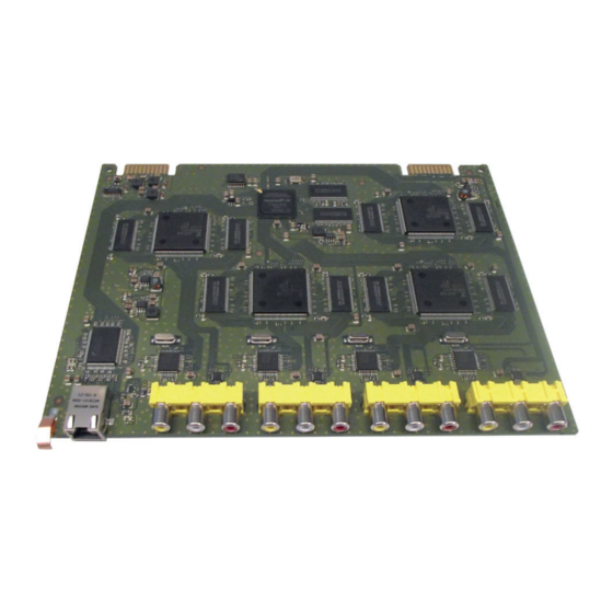
LAN Interface Standard ..............10/100/1000 MB/s Transport stream(s) ......1 MPTS (Multi Programme Transport Stream) or 4 SPTS (Single Programme Transport Stream) Protocols ............UDP (User Data Protocol), RTP (Real-Time Transport Protocol) Connections: Audio inputs: ............4 x 2 Cinch sockets CVBS Video inputs: ............4 Cinch sockets, LAN ................. -
Page 6: Installation
The module is equipped with four video/stereo audio inputs. The fed in ana- logues signals are digitized and supplied to an encoder that encodes them in real time. The stereo audio signals are transferred via an adjustable amplifier to the encoder. At the Ethernet socket (RJ45) up to four SPTS transport streams or one MPTS transport stream (Multi Programme Transportstreams) according to UDP or RTP protocol is output. -
Page 7: Installing The Encoder Module
3.1 i n s ta l l i n g t h e n C o d e r m o d u l e – When installing a module, make sure that it is inserted in one of the long, numbered grooves in front of the contact strip on the board at the rear wall of the housing. -
Page 8: Emc Regulations
3.2 C o n n e C t i n g t h e n C o d e r m o d u l e • Connect the audio inputs (right channel) / (left channel) and video inputs to corresponding signal sources. •... -
Page 9: The Control Panel At A Glance
C o n t r o l p a n e l g l a n C e 4.1 f u n C t i o n s t h e C o n t r o l pa n e l b u t to n s To move the cursor To adjust values and... -
Page 10: Programming
r o g r a m m i n g 5.1 p r o g r a m m i n g p r o C e d u r e Bedienhinweise Operating Hints BE160 SETUP Ein/On "blättert" Menüs vorwärts. scrolls forward through the menu. -
Page 11: Programme Number (Sid - Service Id)
1234 /RTP 1…4 PKTS/FEC 1…7 / 10/09 AnnexB / … / 20/19 AnnexB 1…4 TS/ONID 0x0001,0100 Bx 2 INPUT 1…4 BITRATE /2…15/off/Audio only AV 1 => 5.0 Mbps AV 1…4 1…4 NORM /PAL N PAL BG 4.43 MHz 3.58 MHz 1…4 ASPECT /16:9... -
Page 12: Selecting The Module / Channel Strip
Bx 2 MEMORY Einstellung speichern page 10 store factory defaults S => STORE STORE page 10 CANCEL 5.2 p r o g r a m m i n g t h e m o d u l e Notes: – Entries are saved by pressing the button. -
Page 13: Ethernet Parameters
e l e C t i n g t h e m o d u l e C h a n n e l s t r i p • If necessary, press repeatedly to select the particular module (Bx …) to be programmed. -
Page 14: Ip Address Of The Cassette
• Press the button to activate the setting options. —> The "IP address of the cassette" – "IP-ADDR" submenu is activated. a d d r es s t h e C a s s e t t e If you choose to enter the Ethernet parameters manually, set the IP address of the cassette in this menu. -
Page 15: Udp Port
d d r es s t h e gat e way The address of a gateway (server) can be set in this menu. If no gateway is used you can skip this setting. Bx 2 IP-GATEWAY 192.168. • Use the buttons to select the digit of the IP address displayed to be set and use to set the desired IP address. - Page 16 o u t p u t s i g n a l Herein you select whether you would like to generate – a MPTS data stream, which includes all input signals, or – four SPTS data streams, each one input signal included. In addition you get access to the submenus for IP output and TS/ONID(s) set- tings .
-
Page 17: Output Ip Address
ip u t p u t a d d r es s In this menu you set the output IP address for the selected transport stream. 1…4 OUT-IP 227. 40. 50. 60 —> "IPTV" IP addresses, which are used to send and receive the IPTV channels (e.g. 227.40.50.60) must be within the "multicast" range from 224.5.0.0 to 231.255.255.255. —> For special uses "Unicast" transmission is needed. Therefore the IP address must be outside of the multicast range. - Page 18 • Using the buttons select the digit of the MAC address displayed to be set. • Using the buttons set the desired MAC address. • Press the button. —> The "Transmission protocol / Port number" – "MODE / PORT" sub- menu is activated. / p r a n s m i s s i o n p r oto C o l...
- Page 19 ua n t i t y data paC k e t s / t o rwa r d e r r o r C o r r e C t i o n r a n s m i s s i o n C h a n n e l In this menu you set the quantity of the data packets to be transmitted, the for- ward error correction FEC and the transmission channel.
- Page 20 id orgnet id r a n s p o r t s t r e a m a n d If the input signals are encoded to a separate transport stream (e.g. setting of the output signal path -> ASI without any ASI input signal), a new ORGNET-ID must be assigned to the transport stream.
-
Page 21: Data Rate Of The Video Signal
—> The "Data rate of the video signal " – "BITRATE" submenu is acti- vated. r at e t h e v i d e o s i g n a l You can use this menu to set the data rate at which the video signal is to be encoded. - Page 22 s p e C t r at i o In this menu the aspect ratio of the encoded signal is to be set - "16:9" or "4:3". 1…4 ASPECT • Use the buttons to set the desired aspect ratio. • Press the button.
-
Page 23: Level Of The Audio Signal
The higher the bit rate, the higher the quality of the transmitted audio signal. Bear in mind that when the bit rate is increased, the bandwidth of the output signal is also increased. • Press the button. —> The "Level of the audio signal" –"VOLUME" submenu is activated. e v e l t h e au d i o... -
Page 24: Channel Name
h a n n e l n a m e In this menu the channel name of the input can be set. 1…4 NAME PROG 1 • Use the buttons to select the digit of the channel name to be set and buttons to set the desired character ("... - Page 25 —> The factory defaults are saved. The display shows "STORE" —> Back to "Selecting the module" (page 13). av i n g s e t t i n gs Bx 2 MEMORY STORE S => STORE CANCEL • All programmed data is saved by pressing the button.
-
Page 26: Final Procedures
i n a l p r o C e d u r e s After installing the head-end station, upgrading accessories or installing mod- ules it is necessary to tighten all cable connections, cable terminals and cover screws in order to maintain compliance with current EMC regulations securely. • Mount the base plate and the front cover (see STC 160 assembly instruc- tions). - 26 - HDE 166... -
Page 27: Technical Data
Declaration of CE conformity GSS Grundig SAT Systems GmbH • Beuthener Straße 43 • D-90471 Nuremberg Phone: +49 (0) 911 / 703 8877 • Fax: +49 (0) 911 / 703 9210 www.gss.de/en • info@gss.de Service: Phone: +49 (0) 911/703 2221; Fax: +49 (0) 911/703 2326; service@gss.de Alterations reserved.
Need help?
Do you have a question about the HDE 166 and is the answer not in the manual?
Questions and answers