Advertisement
Quick Links
Advertisement

Related Manuals for GSS HMPT 1000 C


Summary of Contents for GSS HMPT 1000 C
- Page 1 HMPT 1000 C...
- Page 2 o n t e n t s 1 Safety regulations and notes ................ 4 2 General information ..................5 Packing contents ................5 Meaning of the symbols used ............5 Technical data ................5 Description ...................6 Input signal path "INROUTE" ............7 Menu setting "A=1 B=2" ............7 Menu setting "A+B=1 2=OFF" ..........7 Output signal path "OUTROUTE"...
- Page 3 Address of the gateway ..............24 UDP port ..................24 Input signal path ................25 Output signal path ...............25 ASI transfer rate ................26 ASI options................... 26 Channel strip ................27 Selecting channel / frequency setting ..........27 Output frequency, Output channel, Modulator .........28 Output levels of the channel strips ..........29 Input data stream .................29 IP reception, Transmission protocol, Port number ......30 IP address of the input transport stream ..........31...
- Page 4 a f e t y r e g u l a t i o n s a n d n o t e s • Assembly, installation and servicing should be carried out by authorised electricians. • Switch off the operating voltage of the system before beginning with assem- bly or service work or pull out the mains plug.
- Page 5 2.1 P aC k i n g C o n t e n t s 1 Cassette HMPT 1000 C 1 RF cable 1 Brief assembly instructions 2.2 m...
- Page 6 LAN interface Standard: ................100-BASE-T Data rate: ................≤ 80 MBit Protocols: ............UDP (User Data Protocol), RTP (Real-Time Transport Protocol) ASI interface Standard: ..............DIN EN 50083-9 Format: ..............MPEG ISO IEC 13818-1 User data rate: ..............2 … 90 Mbit/s Level (input / output): ............. 800 mV ±...
- Page 7 "inroute" n P u t s i g n a l Pat h "a=1 b=2" e n u s e t t i n g The transport streams of the receiving stage channel strip "A" and of the LAN input channel strip "A" generate optionally the transport stream 1. The trans- port stream of the LAN input channel strip "B"...
- Page 8 "outroute" u t P u t s i g n a l Pat h "1=>ma 2=>mb" e n u s e t t i n g Transport stream 1 is made available via modulator "A", transport stream 2 via modulator "B". Modulator Transport stream 1 "A"...
- Page 9 e n e r a l The cassette is equipped with two channel strips ("A" and "B"). The "A" chan- nel strip has a digital SAT tuner and can process both the transport stream fed in via the LAN interface and the transport stream from the SAT tuner. Using an appropriate CA module, encoded services coming from the SAT tuner can be decoded in channel strip "A".
- Page 10 2.5 s o f t wa r e q u e ry Control unit If necessary, you can activate the indication of the software version of the control unit manually: • Press any two keys on the control unit of the head-end station simultaneously until the display goes dark and the software version, e.g.
- Page 11 2.7 e " " x P l a n at i o n t h e t e r m s ym b o l r at e Modulation schemes such as QPSK and QAM transmit multiple bits simultane- ously. These are referred to as symbols. In addition to the user data flow which transmits video and audio information, error correction bits are transferred.
- Page 12 s s e m b l y 3.1 i n s ta l l i n g t h e C a s s e t t e – Ensure the head-end station is mounted so it will not be able to vibrate. Avoid, for example, mounting the head-end station onto a lift shaft or any other wall or floor construction that vibrates in a similar way.
- Page 13 3.2 emC r e g u l at i o n s To comply with the current EMC regulations, it is necessary to connect the lines leading in and out of the head-end station using cable terminals. When mounting the cassette in a head-end station which is installed in a 19" cabinet, make sure the connections leading in and out for the 19" cabinet are made using cable terminals. The attenuation of shielding of the connection lines for ASI and antenna must meet the requirements for "Class A". CLASS • Insert the required number of cable terminals in the openings provided in the head-end station or in the 19" cabinet. Tighten the nut on the cable terminal until the teeth on the lock washer have pen- etrated the exterior coating and a good connection is made between the housing and cable terminal.
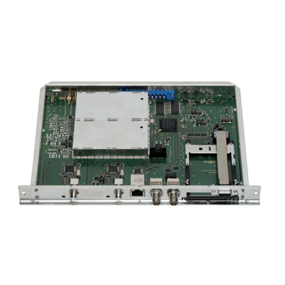
- Page 14 3.3 C a s s e t t e ov e rv i e w Status LED of channel strip "B" Not used Status LED of channel strip "A" SAT IF input of channel strip "A" Status LED of the LAN interface (data transfer) LAN socket Status LED of the LAN interface (network connection) Not used...
- Page 15 3.5 r Ca e t r o f i t t i n g m o d u l e The cassette is equipped with a common interface. It allows you to connect a CA module for various scrambling systems and service providers. Scrambled services (channels) can only be descrambled with a CA module suitable for the scrambling system and the corresponding smart card.
- Page 16 C o n t r o l P a n e l g l a n C e 4.1 m e n u i t e m s Program the cassette using the buttons on the control unit of the head-end sta- tion.
- Page 17 4.2 C o n t r o l Pa n e l The key pad on the head-end station is used to scroll through the menus: scrolls forward through the menus. select parameters in the menus. set values, initiate actions. selects sub-menus.
- Page 18 5.2 P ro g r a m m i n g Pro C e d u r e BE–Remote V 45 Bedienhinweise Operating Hints Ein / On "blättert" Menüs vorwärts. scrolls forward through the menu. please wait … "blättert" Menüs rückwärts. scrolls backward through the menu.
- Page 19 continuous / burst Page 21 Bx 4 LINE ◀ ▶ Line A <= => Line B Line A / Line B Bx 4A OUTPUT Freq. Channel / Freq. Bx 4A OUTPUT ◀ ▶ 850.00 MHz on / off S21 … C69 42…860 MHz Line B Bx 4A...
- Page 20 ◀ ▶ next service (station) on -> off nur Kanalzug “A” mit CA-Modul Bx 1A only Channel strip “A“ with CA module on / off PID Check Bx 1A Menu <= => Edit ◀ ▶ Bx 1A TV 04/09 X / 0 .
- Page 21 on / off Make Bx 4A CAT-ID ◀ ◀ ▶ ▶ 0xDE00 on / off Bx 4A DROP ◀ ▶ ◀ ▶ PID 0x0000 on / off Bx 4A REMAP ◀ ▶ ◀ ▶ 0x0000 –> 0000 on / off Page 18 auf Werkseinstellung Bx 4A...
- Page 22 5.3 P r o g r a m m i n g t h e C a s s e t t e —> Pressing the button for longer than 2 seconds cancels the programming procedure. This takes you back to the programme item "Selecting the cassette"...
- Page 23 t h e r n e t Pa r a m e t e rs In this menu you specify whether the Ethernet parameters for the cassette are entered automatically by a connected server ("DHCP"), or whether you want to enter them manually ("stat"). To assign the cassette uniquely, each IPTV cas- sette must be allocated its own IP address.
- Page 24 d d r es s r a n g e In this menu you define the address range for the cassettes connected to the LAN network. Bx 4 IP-MASK 255.255.255. • Use the buttons to place the cursor under the digit of the IP address displayed to be set and use to set the IP address wished.
- Page 25 • Use the buttons to place the cursor under the digit of the port number displayed to be set and use to set the port number wished ("0" … "65535"). • Press the button. —> The "Input signal path" – "INROUTE" menu is activated. n P u t s i g n a l Pat h...
- Page 26 • Press the button. —> The "ASI transfer rate" – "ASI RATE" menu is activated. asi t r a n s f e r r at e In this menu you set the transfer rate for the ASI component connected. For this setting please take the required information from the documentation (technical data) of the ASI component to be connected.
- Page 27 • To change the type of transmission press the buttons to position the cursor under "cont." (continuous – standard) and using the set to "burst". —> Setting "cont." The data packets of the user data are collected to a great data packet in the transport stream.
- Page 28 interference (overlapping) with the 8 MHz QAM signal packages, thus caus- ing transmission problems. For programming in these channel ranges and in the frequency ranges below them, we recommend starting with channel S21 / 306 MHz going back in steps of 8 MHz (see frequency table on page 48), or reducing the bandwidth of the QAM output signal by removing stations.
- Page 29 u t P u t l e v e l s t h e C h a n n e l s t r i P s This menu item is used to set the output levels of the modulators of the channel strips "A"...
- Page 30 • Press the buttons to select the signal source of the input transport stream ("Lan", "Tuner"). • Press the button. —> Setting "Lan": The "IP reception, Transmission protocol, Port number" – "MODE / PORT" menu is activated. —> Setting "Tuner": The "LNB oscillator frequency" – "LNB" menu is activated. Continue with chapter "Tuner settings", page 41.
- Page 31 • Using the buttons set the port number wished. • Press the button. —> The "IP address of the input transport stream" – "IN-IP" menu is activated. a d d r es s t h e i n P u t t r a n s P o r t s t r e a m In this menu you can set the IP address of the transport stream fed via the LAN...
- Page 32 "inroute" "a = 1 b = 2" m e n u s e t t i n g • Press the button. —> All services from the channel strip will be read, and then displayed with name and type of the service. —> If no service is found, the following message will appear in the dis- play: "FILTER no Service".
- Page 33 • Press the button. —> The filter is activated. The display shows "PROGRAM Filter on". —> If services are activated the corresponding PIDs (audio, video, text) are inserted into the transport stream and the PAT and SDT tables are updated. es t t h e s tat u s...
- Page 34 • Press the button. —> The "QAM modulation, inverting the user signal" – "QAM" menu is activated. Programming the channel strip "A" with a CA module installed the "PID monitoring" – "CA" menu is activated (page 44). qam m o d u l at i o n n v e r t i n g t h e u s e r...
- Page 35 u t P u t s ym b o l r a n g e In this menu, you can modify the output symbol rate. Bx 4A STUFFING SR=6900 (6325) Zahl 1 Zahl 2 Number 1 Number 2 SR=6900 (= "Number 1"): Active output symbol rate (6325) (= "Number 2"): The current measured output symbol rate.
- Page 36 u b s t i t u t e s i g n a l t h e C a s e i n C o r r e C t i n P u t s i g n a l You use this menu to set whether a QAM signal filled with "Null Packets", a QAM signal filled with null packets and self-made tables "Tables"...
- Page 37 (nit) e t wo r k n f o r m at i o n a b l e Bx 4A => Make • To switch NIT on/off ("on"/"off") press the buttons. • Press the button to activate NIT "Make". —> All active cassettes which are able to output a NIT ("NIT cassettes") must be set and ready for reception.
- Page 38 e t wo r k o P e r ato r i d e n t i f i C at i o n In this menu, you can change the network/operator identification (CAT-ID – Conditional Access Table - Identification), for example of the visAvision trans- ponder (Eutelsat 8°...
- Page 39 Pid e l e t i n g In this menu a PID of the transport stream can be deleted. Bx 4A DROP PID 0x0000 • Use the buttons to place the cursor under the respective digit of the hexadecimal number of the PID to be deleted ("0x0000") and set the hexa- decimal number using •...
- Page 40 aC to ry r e s e t In this menu you can reset all settings to the factory defaults. Bx 4A FACTORY Bx 4A FACTORY Defaults => STORE => M • Press the button. —> The factory defaults are invoked ("FACTORY STORE"). —>...
- Page 41 u n e r s e t t i n gs lnb os C i l l ato r f r e q u e n C y Set the oscillator frequency of the LNB used in this menu. Bx 4A 10600 MHz •...
- Page 42 Setting the DVB mode • Use the button to place the cursor under "DVB-S" and set the required DVB-S2-mode with the buttons • Press the button. —> The "Input frequency" – "FREQ" menu is activated. n P u t f r e q u e n C y If three dots "...
- Page 43 es t i n g t h e s i g n a l n o i s e r at i o In this menu you can estimate the quality of the input signal. Bx 4A (+ 9.6) OK 12.0 dB Current signal to noise ratio This value shows the difference between the quality of the input signal...
- Page 44 Ca P e r at i o n w i t h m o d u l e In order for this function of the CA module to be possible, stations / services capable of being descrambled by the CA module and the smart card you are using must be selected in the "Station filter"...
- Page 45 Bx 4A Menu <= => Edit Bx 4A 01/03 MENU Bx 4A TV Bx 4A TV 04/09 04/09 Information *) ..—> The display shows e.g.: Bx 4A 01/03 MENU Information Meaning of the indicators: "Bx 4A" Slot 4, channel strip "A" "01/03"...
- Page 46 es C r a m b l i n g s e rv i C es In this menu you select the services wished from the scrambled data stream, which are to be descrambled. Bx 4A Menu <= => Edit Bx 4A 01/03 Bx 4A 01/03 MENU...
- Page 47 i n a l Pro C e d u res After installing the head-end station, upgrading accessories or installing cas- settes it is necessary to tighten all cable connections, cable terminals and cover screws in order to maintain compliance with current EMC regulations securely. • Securely tighten the cable bolted connections fingertight using an appropri- ate open-ended spanner. • Measure the output levels of the other cassettes and tune them to a uniform output level using the appropriate level controls or software dependent on the head-end station used.
- Page 48 h a n n e l a n d f r e q u e n C y t a b l e s Advice for a frequency grid (8 MHz) in the Band I/III 42.00 82.00 146.00 186.00 226.00 266.00 50.00 114.00...
- Page 49 Phone: +49 (0) 911 / 703 8877 • Fax: +49 (0) 911 / 703 9210 www.gss.de/en • info@gss.de CLASS CLASS Service: Phone: +49 (0) 911/703 2221; Fax: +49 (0) 911/703 2326; service@gss.de Alterations reserved. Technical data E. & O.E. © by GSS Grundig Systems GmbH V39/001/2017...
Need help?
Do you have a question about the HMPT 1000 C and is the answer not in the manual?
Questions and answers