Table of Contents
Advertisement
Quick Links
Advertisement
Table of Contents

Related Manuals for ACME Glamour 350Z


Summary of Contents for ACME Glamour 350Z
-
Page 2: Table Of Contents
CONTENTS 1. Safety Instructions ..................2 2. Technical Specifications ................. 4 3. How To Set The Unit ..................5 3.1 Control Panel ................... 5 3.2 Main Function ..................6 3.3 Home Position Adjustment ..............13 4. Control By Universal DMX Controller ............14 4.1 DMX512 Connection ................ -
Page 3: Safety Instructions
1. Safety Instructions Please read the instruction carefully which includes important information about the installation, usage and maintenance. WARNING Please keep this User Guide for future consultation. If you sell the unit to another user, be sure that they also receive this instruction manual. Important: Damages caused by the disregard of this user manual are not subject to warranty. - Page 4 Unit’s surface temperature may reach up to 75℃. DO NOT touch the housing bare-handed during its operation. Avoid any inflammable liquids, water or metal objects entering the unit. Once it happens, cut off the mains power immediately. DO NOT operate in dirty or dusty environment, do clean fixtures regularly. ...
-
Page 5: Technical Specifications
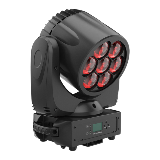
2. Technical Specifications Power Voltage: AC 100~240V, 50/60Hz Power Consumption: 315W (CM-350Z II) 320W (CM-350Z III) Light Source: 7x40W RGBW LED Zoom Range: 5°~50° Movement: Pan: 540° Tilt: 225° Pan/Tilt Resolution: 16bit Dimming/Strobe: 0~100% smooth dimming, variable strobe effects Control: DMX Channel: 11/15/14 Channels Control Mode: DMX, Wireless Control (Optional) Firmware Upgrade: Update via DMX link... -
Page 6: How To Set The Unit
Dimension/Weight: 310x226x412mm, 10.6kgs 12.2"x8.9"x16.2"in, 23.4lbs 310 mm 226 mm Photometric Diagram: 3. How To Set The Unit 3.1 Control Panel 1. Display: To show the various menus and the selected functions... -
Page 7: Main Function
2. LED: POWER Power On DMX input present 3. Button: MENU To enter into move backward or leave the menu DOWN To go forward in the selected functions To go backward in the selected functions ENTER To confirm the selected functions 4. - Page 9 DMX Functions Enter MENU mode, select DMX Functions, press the ENTER button to confirm, use the UP/DOWN button to select DMX Address, DMX Channel Mode, View DMX Value or WDMX Setting. DMX Address To select DMX Address, press the ENTER button to confirm. Use the UP/DOWN button to adjust the address from 001 to 512, press the ENTER button to setup.
- Page 10 Tilt Inverse To select Tilt Inverse, press the ENTER button to confirm. Use the UP/DOWN button to select No (normal) or Yes (tilt inverse), press the ENTER button to setup. Press the MENU button back to the last menu or let the unit idle one minute to exit menu mode. P/T Feedback To select P/T Feedback, press the ENTER button to confirm.
- Page 11 Linear: The increase in light intensity appears to be linear as DMX value is increased. Square Law: Light intensity control is finer at low levels and coarser at high levels. Inverse Square Law: Light intensity control is coarser at low levels and finger at high levels. S-cure: Light intensity control is finger at low levels and high levels and coarser at medium levels.
- Page 12 Backlight Intensity To select Backlight Intensity, press the ENTER button to confirm. Use the UP/DOWN button to adjust the intensity from 1 (dark) to 10 (bright). Once selected, press the ENTER button to setup and store. Press the MENU button back to the last menu or let the unit idle one minute to exit menu mode.
- Page 13 menu mode after auto test. Manual Test To select Manual Test, press the ENTER button to confirm. Use the UP/DOWN button to select channel, and adjust the channel value. Once selected, press the ENTER button to setup, the fixture will run as the channel value indicates. Press the MENU button back to the last menu or exit menu mode let the unit idle one minute.
-
Page 14: Home Position Adjustment
To select All, press the ENTER button to confirm. Use the UP/DOWN button to select No or Yes (the unit will run built-in program to reset all motors to their home positions), press ENTER button to store. Press MENU button to exit menu mode. Special Functions Enter MENU mode, select Special Functions, press the ENTER button to confirm, use the UP/DOWN button to select Fixture Maintenance or Factory Setting. -
Page 15: Control By Universal Dmx Controller
4. Control By Universal DMX Controller 4.1 DMX512 Connection 1. If you using a controller with 5 pins DMX output, you need to use a 5 to 3 pin adapter-cable. 2. The last units DMX cable has to be terminated with a 120 ohm 1/4W resistor between pin 2(DMX-) and pin 3(DMX+) of a 3-pin XLR-plug and plug it in the DMX-output of the last unit. -
Page 16: Address Setting
6. The end of the DMX 512 system should be terminated to reduce signal errors. 7. 3 pin XLR connectors are more popular than 5 pin XLR. 3 pin XLR: Pin 1: GND, Pin 2: Negative signal (-), Pin 3: Positive signal (+) 5 pin XLR: Pin 1: GND, Pin 2: Negative signal (-), Pin 3: Positive signal (+), Pin 4/Pin 5: Not used. - Page 17 000-255 fastslow SHUTTER 000-019 020-024 Open 025-064 Strobe: fast to slow 065-069 Open 070-084 Fast close slow open 085-089 Open 090-104 Fast open slow close 105-109 Open 110-124 Random strobe 125-129 Open 130-144 Random fast close slow open 145-149 Open 150-164 Random fast open slow close 165-169...
- Page 18 15 Channels Mode: CHANNEL VALUE FUNCTION SHUTTER 000-019 020-024 Open 025-064 Strobe: fast to slow 065-069 Open 070-084 Fast close slow open 085-089 Open 090-104 Fast open slow close 105-109 Open 110-124 Random strobe 125-129 Open 130-144 Random fast close slow open 145-149 Open 150-164...
- Page 19 COLOR 000-009 Open 010-014 Color1 015-019 Color2 020-024 Color3 025-029 Color4 030-034 Color5 035-039 Color6 040-044 Color7 045-049 Color8 050-054 Color9 055-059 Color10 060-064 Color11 065-069 Color12 070-074 Color13 075-079 Color14 080-084 Color15 085-089 Color16 090-094 Color17 095-099 Color18 100-104 Color19 105-109 Color20...
- Page 20 000-255 RED (0%100%) 000-255 GREEN (0%100%) 000-255 BLUE (0%100%) 000-255 WHITE (0%100%) 000-255 0%100% 14 Channels Mode: CHANNEL VALUE FUNCTION 000-255 0%100% 000-255 PAN FINE TILT 000-255 0%100% 000-255 TILT FINE PAN/TILT SPEED 000-255 fastslow SPECIAL FUNCTIONS 000-009 No function 010-014 Reset all 015-255...
- Page 21 185-189 Open 190-204 Random burst pulse 205-209 Open 210-224 Slow close slow open 225-229 Open 230-244 Burst 245-255 Open 000-255 RED (0%100%) 000-255 GREEN (0%100%) 000-255 BLUE (0%100%) 000-255 WHITE (0%100%) COLOR 000-009 Open 010-014 Color1 015-019 Color2 020-024 Color3 025-029 Color4 030-034...
-
Page 22: Troubleshooting
155-159 Color30 160-164 Color31 165-169 Color32 170-174 Color33 175-179 Open 180-201 CCW Rotation: fast to slow 202-207 Stop 208-229 CW Rotation: slow to fast 230-234 Open 235-239 Random color rotation (fast speed) 240-244 Random color rotation (medium speed) 245-249 Random color rotation (slow speed) 250-255 Open ZOOM... -
Page 23: Fixture Cleaning
C. One of the channels is not working well 1. The stepper motor might be damaged or the cable connected to the PCB is broken. 2. The motor’s drive IC on the PCB might be out of condition. 6. Fixture Cleaning The cleaning must be carried out periodically to optimize light output. - Page 24 Declaration of Conformity We declare that our products (lighting equipments) comply with the following specification and bears CE mark in accordance with the provision of the Electromagnetic Compatibility (EMC) Directive 2014/30/EU. EN 55103-1: 2009+A1: 2012; EN 55103-2: 2009; EN 55032: 2012; EN 61000-3-2: 2014;...
Need help?
Do you have a question about the Glamour 350Z and is the answer not in the manual?
Questions and answers