Table of Contents
Advertisement
Advertisement
Table of Contents

Subscribe to Our Youtube Channel
Related Manuals for ACME STAGE PAR 400 ZOOM IP


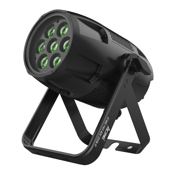
Summary of Contents for ACME STAGE PAR 400 ZOOM IP
-
Page 2: Table Of Contents
CONTENTS 1. Safety Instructions ..................2 2. Technical Specifications ................. 4 3. How To Set The Fixture .................. 5 3.1 Control Panel ................... 5 3.2 Main Functions ..................6 4. How To Control The Unit ................13 4.1 DMX512 Controller ................14 4.2 DMX512 Configuration ................ -
Page 3: Safety Instructions
1. Safety Instructions Please read the instruction carefully which includes important information about the installation, usage and maintenance. WARNING Please keep this User Guide for future consultation. If you sell the unit to another user, be sure that they also receive this instruction manual. Important: Damages caused by the disregard of this user manual are not subject to warranty. - Page 4 off the mains power immediately. DO NOT operate in dirty or dusty environment, do clean fixtures regularly. DO NOT touch any wire during operation as there might be a hazard of electric shock. Avoid power wires together twist other cables. ...
-
Page 5: Technical Specifications
2. Technical Specifications Power Voltage: AC 100~240V, 50/60Hz Power Consumption: 250W Light Source: 7x40W RGBW LED Zoom Range: Beam Angle: 6°~40° Spot Angle: 10°-60° Dimmer/Shutter: Smooth dimming from 0~100%; outstanding strobe effect with variable speed Control: DMX Channel: 5/7/9 channels Control Mode: DMX512, RDM Firmware Upgrade via DMX link Construction:... -
Page 6: How To Set The Fixture
Dimensions/Weight: 295x316x318mm, 8.5kgs 11.6"x12.4"x12.5"in, 18.7lbs Photometrics Diagram: 3. How To Set The Fixture 3.1 Control Panel... -
Page 7: Main Functions
1. Display: To show the menu and the selected functions 2. Button: MENU To select the programming functions DOWN To go forward in the selected functions To go backward in the selected functions ENTER To confirm the selected functions 3. DMX IN: For DMX512 operation, use 5-pin XLR cable to link the DMX controller 4. - Page 9 DMX Setting To select DMX Setting, press the ENTER button to confirm, use the UP/DOWN button to select DMX Address or Channel Mode. DMX Address To select DMX Address, press the ENTER button to confirm. Use the UP/DOWN button to adjust the address from 001 to 512, press the ENTER button to store.
- Page 10 Constant Color To select Constant Color, press the ENTER button to confirm. Use the UP/DOWN button to select No or Yes, press the ENTER button to store. Press the MENU button back to the last menu or let the unit idle 30 seconds to exit menu mode. Dimmer Curve To select Dimmer Curve, press the ENTER button to confirm.
- Page 11 Show Program To select Show Program, press the ENTER button to confirm, use the UP/DOWN button to select Set Scene Totals, Edit Scene Color, Fade Time, Hold Time or Zoom. Set Scene Totals To select Set Scene Totals, press the ENTER button to confirm. Use the UP/DOWN button to adjust the value from 0 to 50.
- Page 12 Manual Mode Select Manual Mode, press the ENTER button to confirm, use the UP/DOWN button to select Clear, Dimmer, Strobe, Red, Green, Blue, White or Zoom. Use the UP/DOWN button to adjust the value from 0 to 255, press the ENTER button to store. Press the MENU button back to the last menu or let the unit idle 30 seconds to exit menu mode.
- Page 13 Fixture Information Select Fixture Information, press the ENTER button to confirm, use the UP/DOWN button to select LED Temperature, Fixture Use Time, Light On Time, Firmware Version, RDM UID or Error Logs. LED Temperature Select LED Temperature, press the ENTER button to confirm, LED temperature will show on the display, press the MENU button to exit.
-
Page 14: How To Control The Unit
Reset Select Reset, press the ENTER button to confirm, present mode will blink on the display, use the UP/DOWN button to select No or Yes, press the ENTER button to store. Press the MENU button back to the last menu or let the unit idle 30 seconds to exit menu mode. Factory Setting Select Factory Setting, press the ENTER button to confirm, present mode will blink on the display, use the UP/DOWN button to select No or Yes, press the ENTER button to store. -
Page 15: Dmx512 Controller
4.1 DMX512 Controller If you use a universal DMX controller to control the units, you have to set DMX address from 1 to 512 so that the units can receive DMX signal. Press the MENU button to enter menu mode, select DMX Setting, press the ENTER button to confirm, use the UP/DOWN button to select DMX Address, press the ENTER button to confirm, the present address will blinking the display, use the UP/DOWN button to adjust the address from 001 to 512, press the ENTER button to store. - Page 16 WHITE 000-255 0%100% ZOOM 000-255 40°6° 7 Channels mode: CHANNEL VALUE FUNCTION 000-255 0%100% GREEN 000-255 0%100% BLUE 000-255 0%100% WHITE 000-255 0%100% DIMMER 000-255 0%100% STROBE 000-014 Open 015-042 Strobe from fast to slow 043-070 Pulse from fast to slow 071-078 Random Strobe 079-106...
- Page 17 9 Channels mode: CHANNEL VALUE FUNCTION 000-255 0%100% GREEN 000-255 0%100% BLUE 000-255 0%100% WHITE 000-255 0%100% DIMMER 000-255 0%100% 000-255 DIMMER FINE STROBE 000-014 Open 015-042 Strobe from fast to slow 043-070 Pulse from fast to slow 071-078 Random Strobe 079-106 Burst from fast to slow 107-114...
- Page 18 060-064 LEE 132 – Medium Blue 065-069 LEE 200 – Double CT Blue 070-074 LEE 161 – Slate Blue 075-079 LEE 201 – Full CT Blue 080-084 LEE 202 – Half CT Blue 085-089 LEE 117 – Steel Blue 090-094 LEE 353 –...
-
Page 19: Dmx512 Connection
4.3 DMX512 Connection 1. At last unit, the DMX cable has to be terminated with a terminator. Solder a 120-ohm 1/4W resistor between pin 2(DMX-) and pin 3(DMX+) into a 3-pin XLR-plug and plug it in the DMX-output of the last unit. 2. -
Page 20: Troubleshooting
5. Troubleshooting Following are a few common problems that may occur during operation. Here are some suggestions for easy troubleshooting: A. The unit does not work, no light and the fan does not work 1. Check the connect power. 2. Measure the mains voltage on the main connector. 3. - Page 23 Declaration of Conformity We declare that our products (lighting equipments) comply with the following specification and bears CE mark in accordance with the provision of the Electromagnetic Compatibility (EMC) Directive 2014/30/EU. EN 55032: 2015; EN 61000-3-2: 2014; EN 61000-3-3: 2013; EN 55103-2: 2009. &...
- Page 24 Innovation, Quality, Performance...
Need help?
Do you have a question about the STAGE PAR 400 ZOOM IP and is the answer not in the manual?
Questions and answers