Table of Contents
Advertisement
Quick Links
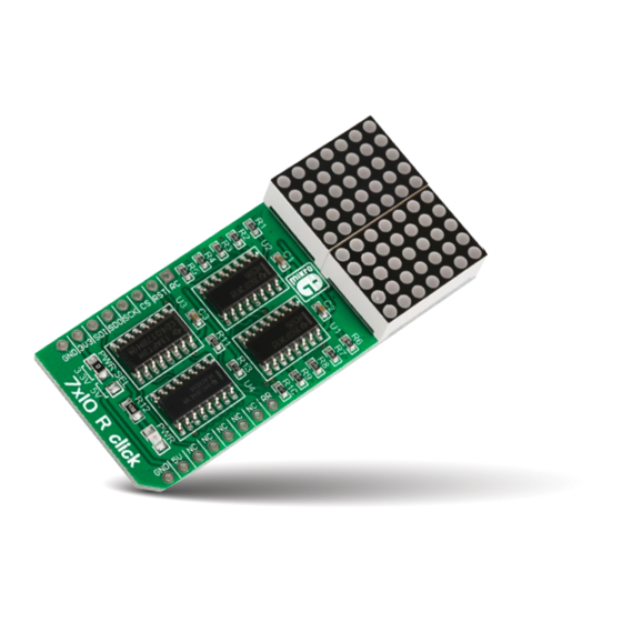
7x10 R
click
1. Introduction
7x10 R click carries a matrix of 70 red LEDs
driven by a pair of 8-bit serial-in, parallel-
out shift registers, a Darlington Transistor
array and a Johnson counter. The click
communicates with the target MCU through
the mikroBUS™ SPI interface (SCK, SDO,
SDI), with additional functionality provided
by R CLK, MR#, LATCH and R RST pins. 7x10
R click is designed to use either a 3.3V or a
5V power supply.
2. Soldering the headers
Before using your click board
™
, make sure
to solder 1x8 male headers to both left and
right side of the board. Two 1x8 male headers
are included with the board in the package.
2
Turn the board upside down so that
the bottom side is facing you upwards.
Place shorter pins of the header into the
appropriate soldering pads.
1
3
Turn the board upward again. Make sure
to align the headers so that they are
perpendicular to the board, then solder the
pins carefully.
3. Plugging the board in
Once you have soldered the headers your
board is ready to be placed into the desired
mikroBUS
socket. Make sure to align the
™
cut in the lower-right part of the board with
the markings on the silkscreen at the
mikroBUS
socket. If all the
™
pins are aligned correctly,
push the board all the way
into the socket.
4. Essential features
7x5 is a standard resolution for displaying
ASCII characters, so 7x10 click is essentially
a dual-character display capable of showing
letters in more readable typefaces compared
to a 14-segment display. The dot matrix can
also show scrolling text, thus fitting longer
messages in small space. The pair of 8-bit
SIPO shift registers drive the display. The
current amplification necessary for driving
the LEDs is performed by a Darlington
Transistor array while a Johnson counter
performs the necessary LED multiplex.
click
BOARDS
™
www.mikroe.com
7x10 R click Manual v101
0 1 0 0 0 0 0 0 8 8 9 7 5
Advertisement
Table of Contents

Related Manuals for mikroElektronika 7x10 R click


Summary of Contents for mikroElektronika 7x10 R click
- Page 1 LED multiplex. 1. Introduction 3. Plugging the board in click 7x10 R click carries a matrix of 70 red LEDs driven by a pair of 8-bit serial-in, parallel- Once you have soldered the headers your out shift registers, a Darlington Transistor...
- Page 2 ULN2003 6. Dimensions 7. SMD jumper 10. Disclaimer MikroElektronika assumes no responsibility 7x10 R click features an mils SMD jumper (zero ohm or liability for any errors or inaccuracies resistor) that let’s you that may appear in the present document.
Need help?
Do you have a question about the 7x10 R click and is the answer not in the manual?
Questions and answers