Advertisement
Quick Links
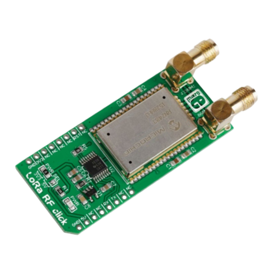
LoRa RF
click
1. Introduction
LoRa RF click carries Microchip's RN2483
fully certified LoRa Sub-GHz, 433/868 MHz
European R&TTE Directive Assessed Radio
Modem. Two antenna connectors allow
you to choose which of the two frequency
bands will be employed. LoRa RF click
communicates with the target board MCU
through the mikroBUS
UART interface (CTS,
™
TXD, RXD), with the addition of a Reset pin
(RST). The board is designed to use either a
3.3V or a 5V power supply.
2. Soldering the headers
Before using your click board
™
, make sure
to solder 1x8 male headers to both left and
right side of the board. Two 1x8 male headers
are included with the board in the package.
2
Turn the board upside down so that
the bottom side is facing you upwards.
Place shorter pins of the header into the
appropriate soldering pads.
1
3
Turn the board upward again. Make sure
to align the headers so that they are
perpendicular to the board, then solder the
pins carefully.
3. Plugging the board in
Once you have soldered the headers your
board is ready to be placed into the desired
mikroBUS
socket. Make sure to align the
™
cut in the lower-right part of the board with
the markings on the silkscreen at the
mikroBUS
socket. If all the
™
pins are aligned correctly,
push the board all the way
into the socket.
4. Essential features
LoRa wireless technology enables low power
consumption and a long range. The RN2483
transceiver module has a specified range of
>15km in rural and suburban settings, and
>5km coverage in urban areas. A LoRaWAN
Class
A
protocol
stack
is
embedded
(bidirectional end devices), as well as an ASCII
command interface accessible through UART.
The high receiver sensitivity can go down to
-148 dBm. Applications include Automated
Meter Reading, Home and Building Automation,
M2M, IoT, Industrial Monitoring and Control.
click
BOARDS
™
www.mikroe.com
LoRa RF click Manual v102
0 1 0 0 0 0 0 0 9 1 9 1 3
™
Advertisement

Related Manuals for mikroElektronika MIKROE-1993


Summary of Contents for mikroElektronika MIKROE-1993
- Page 1 2. Soldering the headers Before using your click board ™ , make sure to solder 1x8 male headers to both left and right side of the board. Two 1x8 male headers are included with the board in the package. LoRa RF click 4.
- Page 2 GPIO7 RESERVED LP2985 M_CTS GPIO8 UART CTS GPIO9 UART RTS VOUT MikroElektronika offers free tech support SHDN (www.mikroe.com/support) until the end of 10nF the product’s lifetime, so if something goes wrong, we’re ready and willing to help! 4.7uF 100nF 10uF...
Need help?
Do you have a question about the MIKROE-1993 and is the answer not in the manual?
Questions and answers