Table of Contents
Advertisement
Quick Links
Advertisement
Table of Contents

Subscribe to Our Youtube Channel
Related Manuals for THORLABS vytran LDC450B


Summary of Contents for THORLABS vytran LDC450B
- Page 1 LDC450B Large Diameter Fiber Cleaver User Guide...
-
Page 3: Table Of Contents
LDC450B Table of Contents Warning Symbol Definitions ....................1 Chapter 1 Safety ............................ 2 Chapter 2 Description ........................... 3 Chapter 3 3.1. Introduction ........................3 3.2. Parts Checklist ........................ 3 3.3. Shipping Fixture ......................4 3.4. Accessories ........................5 3.5. Control Overview ......................6 3.6. - Page 4 9.1. Fiber Holder Inserts ...................... 44 Specifications ........................48 Chapter 10 Servicing and Troubleshooting ..................49 Chapter 11 11.1. Packaging ........................49 11.2. Frequently Asked Questions ..................50 Chapter 12 Regulatory ...........................51 Chapter 13 CE Certificate ........................52 Chapter 14 Thorlabs Worldwide Contacts ..................53...
-
Page 5: Chapter 1 Warning Symbol Definitions
LDC450B Large Diameter Cleaver Chapter 1: Warning Symbol Definitions Warning Symbol Definitions Chapter 1 Below is a list of warning symbols you may encounter in this manual or on your device. Symbol Description Direct Current Alternating Current Both Direct and Alternating Current Earth Ground Terminal Protective Conductor Terminal Frame or Chassis Terminal... -
Page 6: Chapter 2 Safety
LDC450B Large Diameter Cleaver Chapter 2: Safety Safety Chapter 2 All statements regarding safety of operation and technical data in this instruction manual will only apply when the unit is operated correctly. WARNING Use great care when working near or handling the cleave blade, as the diamond tip is extremely sharp and can very easily cut through skin. -
Page 7: Chapter 3 Description
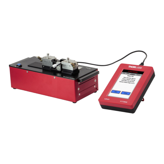
LDC450B Large Diameter Cleaver Chapter 3: Description Description Chapter 3 3.1. Introduction The LDC450B Large Diameter Fiber Cleaver is designed for cleaving optical fibers with claddings from Ø200 μm to Ø800 μm with a high degree of accuracy. Intended to be a portable device, this unit provides ease of use and versatility in manufacturing or research environments. -
Page 8: Shipping Fixture
If you are missing any of the accessories or need replacements, please contact the distributor from whom you bought the cleaver. Visit https://www.thorlabs.com/locations.com for contact information. NOTE: Please save the packaging material for returning the unit back to Thorlabs for service. This packaging will reduce the risk of damage during shipment. -
Page 9: Accessories
Alternatively a Transfer Insert can be used in place of the bottom insert in the left fiber holding block. This Transfer Insert can be used to move the fiber to a Thorlabs Splicer after the fiber is cleaved. Rev A, July 28, 2020... -
Page 10: Control Overview
LDC450B Large Diameter Cleaver Chapter 3: Description Transfer Insert Figure 5 Inserts 3.5. Control Overview 3.5.1. Buttons The LDC450B fiber cleaver has two buttons: a silver-colored power button in the back and a blue “Start” button in the front. • The power button is used for powering up the unit and for turning it off. - Page 11 LDC450B Large Diameter Cleaver Chapter 3: Description 3.6.1. Handset Controller The LDC450B fiber cleaver comes with a Handset Controller that is used for changing parameters and doing maintenance. It is not required for normal operation of the unit if the proper parameters have been loaded. The Handset Controller provides a simple, easy to use interface for configuring, controlling and monitoring the LDC450B.
-
Page 12: Chapter 4 Setup
LDC450B Large Diameter Cleaver Chapter 4: Setup Setup Chapter 4 4.1. Initial Setup 1. Plug in the AC power cord. The power supply accepts an AC input of 100-240 VAC; 47-63 Hz. Do not use a mains supply cord that is rated for less than 1.5A. 2. -
Page 13: Power-Up
LDC450B Large Diameter Cleaver Chapter 4: Setup 6. Place the appropriate top insert into the lids of the fiber holding blocks and tighten the set screws to lock them in place. Note that the inserts are double-sided, and it may be necessary to flip them over in order to find the size you are require. -
Page 14: Performing The First Cleave
LDC450B Large Diameter Cleaver Chapter 4: Setup 4.3. Performing the First Cleave When the status LED is steady green, the unit is ready to perform a cleave. Ensure that the proper inserts are in place, ensure that the correct parameters have been loaded, and ensure you have stripped and cleaned the fiber properly. -
Page 15: Chapter 5 Theory Of Cleaving
LDC450B Large Diameter Cleaver Chapter 5: Theory of Cleaving Theory of Cleaving Chapter 5 The LDC450B automated fiber cleaver is designed for cleaving optical fibers with claddings from Ø200 µm up to Ø1.25 mm. It is possible to cleave smaller fibers as well, but the smaller fibers are more difficult to position correctly in the v-grooves. -
Page 16: Chapter 6 Cleaving
LDC450B Large Diameter Cleaver Chapter 6: Cleaving Cleaving Chapter 6 6.1. Overview The LDC450B cleaves fiber using the tension-and-scribe technique as follows: 1. A stripped fiber is secured in Fiber Holding Blocks (FHBs). 2. The left FHB moves to the left, tensioning the fiber. 3. - Page 17 LDC450B Large Diameter Cleaver Chapter 6: Cleaving While it is typically preferable to clamp directly on the cladding (bare glass) on the discard side, it is also possible to center-strip the fiber and to clamp on the buffer. This may be advantageous for certain types of non-circular fiber that would otherwise rotate uncontrollably during clamping.
-
Page 18: The Fiber Holding Blocks, Inserts, Lifting Levers, And Thumbscrews
LDC450B Large Diameter Cleaver Chapter 6: Cleaving 6.3. The Fiber Holding Blocks, Inserts, Lifting Levers, and Thumbscrews The Fiber Holding Blocks (FHBs) are designed to accommodate a wide range of fiber buffer and cladding sizes through the use of changeable top and bottom fiber holder inserts, which must be purchased separately. The bottom inserts feature V-grooves and are available in three varieties. - Page 19 LDC450B Large Diameter Cleaver Chapter 6: Cleaving Lifting levers are used to overcome the very high clamping forces of the FHB magnets. To lift the FHB lid, press down on the lifting lever first, and then lift the Lid. When closing an FHB Lid, make sure that the lever is in the downward position: this will prevent the FHB lid from slamming down on the fiber, possibly damaging it.
-
Page 20: Stripping The Fiber
LDC450B Large Diameter Cleaver Chapter 6: Cleaving of these magnets alternates, and can most easily be determined by a rod-shaped magnet that is easy to hold between two fingers. 6.4. Stripping the Fiber The fiber end should be stripped down to the cladding over a sufficient length to allow for the desired post cleave length plus the discard length. - Page 21 LDC450B Large Diameter Cleaver Chapter 6: Cleaving Figure 14 Positioning a Fiber in the Left-Hand FHB V-Groove 4. Check that the lifting levers are in the downward position and carefully lower the left-hand FHB lid. 5. With the lifting lever in the downward position the lid will not contact the fiber and the fiber is still free to move.
-
Page 22: Cleaving The Fiber
LDC450B Large Diameter Cleaver Chapter 6: Cleaving 6.6. Cleaving the Fiber To cleave the fiber: 1. Confirm that the fiber is loaded properly and that both levers are raised. 2. Initiate the Cleave Process by pressing the blue START button on the unit or the START button on the Handset Controller. -
Page 23: Unloading The Fiber
Remove any fibers and/or discards from the FHBs and cycle the power OFF then ON. The cleaver will initialize and attempt to run the homing process again. If any further difficulty is experienced, contact techsupport@thorlabs.com for assistance. Figure 16... -
Page 24: Changing The Fiber Holding Block Inserts
LDC450B Large Diameter Cleaver Chapter 6: Cleaving 6.8. Changing the Fiber Holding Block Inserts Both the top and bottom FHB Inserts must be selected according to the diameter of the fiber being clamped. It is common to have a set of inserts for larger diameters in the left-hand FHB for clamping on the coating, and a set for smaller diameters in the right-hand FHB, which typically clamps on the cladding. - Page 25 LDC450B Large Diameter Cleaver Chapter 6: Cleaving To change the bottom V-groove insert: Loosen the set screws accessible from the front of the FHB base using the 0.035” hex key included in the tool kit. Do NOT remove the set screws completely; one full turn counterclockwise should be sufficient to release the insert.
-
Page 26: Specialty Cleave Process
LDC450B Large Diameter Cleaver Chapter 6: Cleaving 6.9. Specialty Cleave Process Two additional process capabilities are available on these cleavers. These processes are primarily utilized for specialty fiber cleaving such as microstructured fiber, highly stressed fibers (usually PM), or capillary tubing. The specialty fiber processes are used to improve end face quality but require the execution of additional steps. - Page 27 LDC450B Large Diameter Cleaver Chapter 6: Cleaving The Micrometer Backstop acts as a backing for the fiber during the Cleave Process. When using the Micrometer Backstop, it is possible to reduce the tension applied to the fiber because the Micrometer Backstop will prevent the fiber from flexing when struck by the blade to produce a longer initial scribe.
-
Page 28: Chapter 7 Using The Handset To Control The Ldc450B
LDC450B Large Diameter Cleaver Chapter 7: Using the Handset to Control the LDC450B Using the Handset to Control the LDC450B Chapter 7 The Handset Controller provides a simple, easy to use interface for configuring, controlling and monitoring the LDC450B. The following sections contain a quick start guide followed by a more detailed view of the features and capabilities of the Handset Controller. -
Page 29: Edit
LDC450B Large Diameter Cleaver Chapter 7: Using the Handset to Control the LDC450B Figure 22 Cleave Screen showing Cleave Status 7.3. Edit Swiping right or pressing on Edit will show the Edit Screen. The Edit Screen gives access to all the parameters that control the Cleave Process. - Page 30 LDC450B Large Diameter Cleaver Chapter 7: Using the Handset to Control the LDC450B 7.3.1. Cleave Parameters Parameter Description The diameter of the fiber cladding to be cleaved. Other recommended values are Fiber Diameter derived from this. This parameter is the load, in grams, applied axially to the fiber prior to initiating the scribe.
- Page 31 LDC450B Large Diameter Cleaver Chapter 7: Using the Handset to Control the LDC450B This parameter is used to enable or disable the Sub-critical cleaving process. When Sub-critical Cleave disabled, the LDC will perform a regular ‘tension-and-scribe’ cleave. This parameter can be set by the user to indicate the number of times the Cleave Cleave Blade Index Blade height has been adjusted (see section 8.3).
-
Page 32: File
LDC450B Large Diameter Cleaver Chapter 7: Using the Handset to Control the LDC450B 7.3.2. Parameter Limit Minimum and maximum Parameter values permitted by the Handset Controller are given below. Parameter Default 10 μm 1500 μm Fiber Diameter Fiber Size Dependent Cleave Tension Fiber Size Dependent 6500 g... - Page 33 LDC450B Large Diameter Cleaver Chapter 7: Using the Handset to Control the LDC450B Open File: Open a fiber file that has been saved onto the internal storage of the Handset Controller. Figure 25 Open File Will List Current Files Saved to the Handset Save File: Overwrite the current fiber file with any changes that have been made to the parameters.
-
Page 34: Tools
LDC450B Large Diameter Cleaver Chapter 7: Using the Handset to Control the LDC450B Delete File: Delete any fiber file that has been saved to the internal storage of the Handset Controller. Export Files: Export any saved fiber file on the Handset Controller to a connected USB flash drive plugged into the side USB port. - Page 35 LDC450B Large Diameter Cleaver Chapter 7: Using the Handset to Control the LDC450B Tools – Motor Control (Select) Figure 28 The Motor Control window provides a numeric window where the user can type in the desired motor position. After pressing Enter, the move is initiated. The motors can either be jogged in the positive or negative direction by fixed increments.
- Page 36 LDC450B Large Diameter Cleaver Chapter 7: Using the Handset to Control the LDC450B Tools – Auto Parameter Figure 29 7.5.3. Blade Service Blade Service provides a window that allows the user to move the blade between its Service Position and its Home Position.
- Page 37 LDC450B Large Diameter Cleaver Chapter 7: Using the Handset to Control the LDC450B 7.5.4. Terminal The handset controller provides a command terminal to send and receive commands to the PTR407B. To send a command, select the line just above the “Send” and “Close” buttons. This will open a keyboard for sending commands.
- Page 38 LDC450B Large Diameter Cleaver Chapter 7: Using the Handset to Control the LDC450B The user will also have the ability to update the handset controller through this menu via USB. This can be accomplished easily by placing the acquired update file from Vytran into the root directory of a USB drive and pressing Update in the Version menu.
- Page 39 LDC450B Large Diameter Cleaver Chapter 7: Using the Handset to Control the LDC450B Figure 34 Password Change Screen Enter the desired new password then press Ok. The following User Access Levels can be set. • Full Access: allows full read-write access of parameters and files, the ability to change User Access Permissions.
- Page 40 LDC450B Large Diameter Cleaver Chapter 7: Using the Handset to Control the LDC450B Figure 35 User- Three Levels of User Access Displayed at the Top of the Screen File Menu with “No read or write” enabled Figure 36 Page 36 TTN197399-D02...
-
Page 41: Chapter 8 Maintenance
LDC450B Large Diameter Cleaver Chapter 8: Maintenance Maintenance Chapter 8 These cleavers are designed to provide trouble-free operation in a production environment provided that planned maintenance is performed as described below. Planned Maintenance Schedule • Inspect and clean the Fiber Holding Blocks every shift. •... -
Page 42: Inspecting The Cleave Blade
LDC450B Large Diameter Cleaver Chapter 8: Maintenance 8.2. Inspecting the Cleave Blade The diamond edge of the Cleave Blade should be inspected daily for debris and/or damage which may result in sub-optimal cleave performance. For easier inspection and cleaning, the Blade Service tool may be selected from the Handset Controller tools (Section 7.5.3). -
Page 43: Re-Positioning The Cleave Blade
LDC450B Large Diameter Cleaver Chapter 8: Maintenance 8.3. Re-Positioning the Cleave Blade Only a small portion of the Cleave Blade edge is used to scribe the fiber. If this local portion of the edge gets damaged, the blade can be re-positioned to a new “un-used” section. While the lifetime of a given section of the blade can be very long (greater than 5,000 cleaves), it is also very easy to damage the blade due to excessive lateral stresses (stresses perpendicular to the edge of the blade). -
Page 44: Replacing The Cleave Blade
LDC450B Large Diameter Cleaver Chapter 8: Maintenance Figure 40 Adjusting the Height of the Cleave Blade 8.4. Replacing the Cleave Blade If the Cleave Blade is sufficiently damaged along its edge such that it cannot be re-positioned to an “un-used” section, then replacement is required. - Page 45 LDC450B Large Diameter Cleaver Chapter 8: Maintenance Select the Blade Service tool function in the Handset Controller. This function will move the Cleave Blade forward to the cleave position. Loosen the set screw in the top of the Cleave Arm one full turn counter-clockwise, using the 0.035″ hex key provided.
-
Page 46: Load Cell Calibration
The load cell calibration should be checked every year to ensure that accurate Cleave Tension is applied to the fiber and that optimal cleave angle and end-face quality is achieved. This task must be performed by a Thorlabs- certified technician. - Page 47 LDC450B Large Diameter Cleaver Chapter 8: Maintenance To remove the old battery, follow these steps: Remove the battery access panel using a small flat head screw driver. Note that the battery panel screws are captive to the battery access panel, so you don’t need to worry about them falling out.
-
Page 48: Chapter 9 Accessories
Bottom Inserts are required to operate the Cleaver. Available Inserts are described below, and the Insert Selection Guide in Section 9.1 should be used to select the appropriate Inserts for each holding block. Top Inserts The table below summarizes the top Fiber Holder Inserts that are available from Thorlabs. Side 1 Min/Max Side 2 Min/Max... - Page 49 LDC450B Large Diameter Cleaver Chapter 9: Accessories Typically, the Transfer Inserts are only be used in the left Fiber Holding Block, as the right Fiber Holding Block usually clamps the side of the fiber that will be discarded. The right Fiber Holding Block of the LDC450B can accept Transfer Inserts, if desired.
- Page 50 LDC450B Large Diameter Cleaver Chapter 9: Accessories Fiber Holder Insert Selection Chart Top Insert Item # VHA25 VHA30 VHA00 VHA05 VHA10 VHA15 VHA20 Accepted Diameter ≤320 µm 400 µm 500 µm 750 µm 1000 µm 1250 µm 1500 µm 1750 µm 2000 µm 2250 µm 2500 µm...
- Page 51 The LFS4100 splicer and GPX series of glass processing stations require extra support for the fiber tips close to the heating filament for fibers with cladding diameters ≤550 µm. For this purpose, Thorlabs offers graphite tips with V-grooves that can be installed in the transfer Inserts. Available graphite tips are outlined in the table below.
-
Page 52: Chapter 10 Specifications
LDC450B Large Diameter Cleaver Chapter 10: Specifications Chapter 10 Specifications LDC450B Cleave Type Flat Cleave Cladding: Ø200 µm to Ø800 μm Accepted Fiber Sizes Buffer: Ø250 µm to Ø3.2 mm SM, PM, MM, Specialty Fibers Including Accepted Fiber Types Photonic Crystal Fiber (PCF) and Non-Circular Fiber, Capillary Tubes Cleave Method Tension and Scribe... -
Page 53: Chapter 11 Servicing And Troubleshooting
Note: Please keep the original packaging and bag that the unit came in. Reuse it if your system needs to be returned to Thorlabs for service or evaluation.The illustrations below show the correct way to re-pack the LDC450B. Please ensure that the bottom of the box is taped securely before re-packing the unit. If returning a malfunctioning unit for repair, we ask that you return the accessories with the unit in case one of the accessories happens to be the source of the problems. -
Page 54: 11.2. Frequently Asked Questions
One way to check cleave quality is to use an interferometric cleave checker. However, if you are working with a GPX3400, GPX3600, or LFS4100 fusion splicer, it is much more efficient to use the GUI to measure the cleave angles and view the endface. For other questions, contact techsupport@thorlabs.com. Page 50 TTN197399-D02... -
Page 55: Chapter 12 Regulatory
Waste Treatment is Your Own Responsibility If you do not return an “end of life” unit to Thorlabs, you must hand it to a company specialized in waste recovery. Do not dispose of the unit in a litter bin or at a public waste disposal site. -
Page 56: Chapter 13 Ce Certificate
LDC450B Large Diameter Cleaver Chapter 13: CE Certificate Chapter 13 CE Certificate Page 52 TTN197399-D02... -
Page 57: Chapter 14 Thorlabs Worldwide Contacts
LDC450B Large Diameter Cleaver Chapter 14: Thorlabs Worldwide Contacts Chapter 14 Thorlabs Worldwide Contacts For technical support or sales inquiries, please visit us at www.thorlabs.com/contact for our most up-to-date contact information. USA, Canada, and South America UK and Ireland Thorlabs, Inc. - Page 58 www.thorlabs.com...
Need help?
Do you have a question about the vytran LDC450B and is the answer not in the manual?
Questions and answers