
Subscribe to Our Youtube Channel
Related Manuals for THORLABS MAX300 Series


Summary of Contents for THORLABS MAX300 Series
- Page 1 MAX300 Series NanoMax 3-Axis Flexure Stage User Guide Original Instructions HA0094T...
-
Page 2: Table Of Contents
Chaper 7 Regulatory ....................21 7.1 Declarations Of Conformity ............21 7.1.1 For Customers in Europe ..............21 7.1.2 For Customers In The USA ..............21 7.2 CE Certificate ................... 22 Chaper 8 Thorlabs Worldwide Contacts ..............23 Page 0 10997-D02... -
Page 3: Chaper 1 Overview
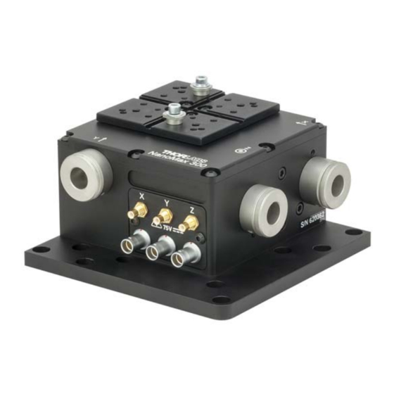
1.1 Description of the NanoMax 3-Axis Flexure Stage The NanoMax 3-axis flexure stage has been designed to integrate seamlessly into the Thorlabs Modular Electronic System and provide nanometric positioning on three orthogonal axes. It is suited to the alignment of optical fibres, waveguides, optoelectronic packages and any other high resolution alignment or positioning application including general purpose laboratory tasks. - Page 4 SMC connector (see Fig. 1.1 and Fig. 1.2). In addition, the MAX301 has a 7- pin LEMO connector for each feedback channel (see Fig. 1.1). A corresponding number of leads for connection to the Thorlabs piezoelectric controllers are also supplied.The piezo-actuated models deliver 20 microns of travel, with a coaxial SMC connector for each piezo channel.
-
Page 5: Drives And Actuators
Chapter 1 Overview Fig. 1.4 MAX303 NanoMax without piezo-actuation The MAX303 has no electrical connections. 1.2.2 Drives and Actuators There are three types of drive available for the NanoMax, a motorized drive as shown in Fig. 1.5. and two manual drives as shown in Fig. 1.6. In addition, external piezo actuators are available to give an additional 20 µm piezo travel –... - Page 6 MAX300 Series 3-Axis Flexure Stages DRV3 differential micrometer drive DRV004 thumbscrew drive Fig. 1.6 Manual Drives The external piezo actuator can be fitted in-line with the standard drives described on the previous page. The DRV120 provides an additional 20 µm of piezo travel.
-
Page 7: Chaper 2 Safety
Warning If the device is used in a manner not specified by Thorlabs, the protective features provided by the product may be impaired. In particular, excessive moisture may impair operation. -
Page 8: Chaper 3 Operation
MAX300 Series 3-Axis Flexure Stages Chapter 3 Operation 3.1 Manual Differential Drives and Differential Micrometer Drives 3.1.1 Adjusting Micrometer Drives Turn the coarse adjustment clockwise until the platform of the NanoMax begins to move. By use of the fine adjustment, sub-micron resolution is now achievable. - Page 9 The host PC must be running Kinesis v1.14.12 or higher. 1) Ensure that the device is connected to the PC and powered up. 2) Run the Kinesis software - Start/All Programs/Thorlabs/Kinesis/Kinesis. 3) On start-up, the 'Actuator/Startup Settings' window is displayed. This window allows the correct actuator to be selected.
- Page 10 MAX300 Series 3-Axis Flexure Stages 4) Select your stage type (e.g. NanoMax 300 X-Axis (DRV208) if you have a NanoMax stage fitted with DRV208 actuators on the X-axis) as shown in Fig. 3.2. 5) Click OK. 6) The server reads in the stage and controller information automatically.
- Page 11 1) Shut down all applications using the APT server (e.g. APT User or your own custom application). 2) Run the APT Config utility - Start/All Programs/Thorlabs/APT Config/APT Config. 3) From the 'APT Configuration Utility' window, click the 'Stage' tab. Fig. 3.3 APT Configuration Utility - Stage Tab 4) In the ‘Motor’...
- Page 12 MAX300 Series 3-Axis Flexure Stages start up. Refer to the handbook for the associated controller for more information on driving the actuator/stage. Note These stepper motor drives have no forward limit switch and the travel is limited dependent on the axis to which it is attached. When the DRV208 motors are used with our Nanomax series stages, suitable defaults are loaded at start up to prevent the motor being overdriven.
-
Page 13: Piezo Actuators
On a piezo-actuated NanoMax, position feedback may be incorporated on the linear axes to enhance the repeatability and linearity of piezo motion. The piezo-actuated NanoMax should be used together with one of the Thorlabs piezoelectric controllers – see the handbook for the relevant piezoelectric controller. -
Page 14: Chaper 4 Installation
4.2 Attaching to a Work Surface The base of the NanoMax is provided with a number of fixing holes and slots for attachment to metric or inch optical tables, as supplied by Thorlabs and other manufacturers. When mounting the NanoMax close to other equipment, ensure that the travel of the moving platform is not obstructed. -
Page 15: Fitting And Removal Of Drives
Chapter 4 Installation 4.3 Fitting and Removal of Drives The following procedure details how to fit a drive to the NanoMax 300 stage. A micrometer drive is shown for illustration purposes but the procedure is equally applicable to motor or thumbscrew actuators. 1) For manual drives, rotate the coarse adjuster counter-clockwise a few turns to retract the drive rod. -
Page 16: Orienting The Moving Platform
MAX300 Series 3-Axis Flexure Stages 4.4 Orienting the Moving Platform The stage is normally oriented such that the X axis is the optical axis. If it is necessary to change the orientation for left or right-handed use, the Y axis becomes the optical axis as shown in Fig. -
Page 17: Mounting Equipment
The weight attached to the moving platform must not exceed 1 kg. Thorlabs manufactures a variety of fibre chucks, holders and fixtures to fit the NanoMax stage. However, custom hardware can be designed using a tongue-in- groove arrangement and the cleats provided, see Fig. -
Page 18: Dimensions
MAX300 Series 3-Axis Flexure Stages 4.7 Dimensions 4.7.1 Top Platform 60.0 (2.36) all dimensions in millimetres (inches) 3 Pitches of 15.00 (0.59) = 45.0 (1.77) 17.0 (0.67) 17.0 (0.67) 4.0 (0.16) (0.3) 10.0 (0.39) 10.0 (0.39) 1.6 (0.06) 5.3 (0.21) 5.3 (0.21) -
Page 19: Replacing The Top Platform
Chapter 4 Installation 4.8 Replacing the Top Platform If desired, the top platform can be replaced by one of the AMA series extended platforms shown in the dimensions section, or by the RB13P1 adapter plate which offers an array of 1/4”-20 (M6) and 8-32 (M4) mounting holes. A replacement grooved top plate (MMP1) is also available. -
Page 20: Chaper 5 Maintenance And Troubleshooting
If for any reason the stage is operated with the micrometer drives removed, blanking plugs (DRV000 available as a custom from Thorlabs) must be fitted before the pizo actuators can function. -
Page 21: Chaper 6 Specifications
The resolution of a manual drive corresponds to a 0.5 degree adjustment of the thimble; the actual resolution obtained depends on the skill of the user. The resolutions of the piezo actuators are those typically obtained using Thorlabs controllers. Piezo Capacitance 3.6 µF... - Page 22 MAX300 Series 3-Axis Flexure Stages Arcuate Displacement The measured maximum cross talk to the Z axis, when a movement is demanded in X or Y is <88 µm. The table below shows the theoretical amount of cross talk to the Z axis, for movement at various X positions (Y axis at zero).
-
Page 23: Chaper 7 Regulatory
Chapter 7 Regulatory Chapter 7 Regulatory 7.1 Declarations Of Conformity 7.1.1 For Customers in Europe See Section 7.2. 7.1.2 For Customers In The USA This equipment has been tested and found to comply with the limits for a Class A digital device, pursuant to part 15 of the FCC rules. -
Page 24: Ce Certificate
MAX300 Series 3-Axis Flexure Stages 7.2 CE Certificate Page 22 10997-D02... -
Page 25: Chaper 8 Thorlabs Worldwide Contacts
Waste treatment is your own responsibility. "End of life" units must be returned to Thorlabs or handed to a company specializing in waste recovery. Do not dispose of the unit in a litter bin or at a public waste disposal site. - Page 26 www.thorlabs.com...
Need help?
Do you have a question about the MAX300 Series and is the answer not in the manual?
Questions and answers