
Related Manuals for THORLABS Vytran LDC401


Summary of Contents for THORLABS Vytran LDC401
- Page 1 LDC401 & LDC401A Automated Cleavers for Fibers with Ø80 µm to Ø1.25 mm Claddings User Guide...
-
Page 3: Table Of Contents
LDC401 & LDC401A Automated Cleavers Table of Contents Chapter 1 Warning Symbol Definitions .................... 1 Chapter 2 Safety ............................ 2 Chapter 3 Description ........................... 3 3.1. Introduction ........................3 3.2. Parts Checklist ........................ 3 Chapter 4 Set-up ............................ 6 4.1. Initial Set-up ........................6 4.2. Power-Up .......................... 7 4.3. ... - Page 4 Chapter 10 Accessories .........................47 10.1. Fiber Holder Inserts ...................... 47 Chapter 11 Specifications ........................51 Chapter 12 Servicing and Troubleshooting ..................52 12.1. Packaging ........................52 12.2. Frequently Asked Questions ..................53 12.3. Toubleshooting ......................54 Chapter 13 Regulatory ...........................55 Chapter 14 Thorlabs Worldwide Contacts ..................56 ...
-
Page 5: Chapter 1 Warning Symbol Definitions
LDC401 & LDC401A Automated Cleavers Chapter 1: Warning Symbol Definitions Chapter 1 Warning Symbol Definitions Below is a list of warning symbols you may encounter in this manual or on your device. Symbol Description Direct Current Alternating Current Both Direct and Alternating Current Earth Ground Terminal Protective Conductor Terminal Frame or Chassis Terminal... -
Page 6: Chapter 2 Safety
LDC401 & LDC401A Automated Cleavers Chapter 2: Safety Chapter 2 Safety CAUTION Damage to the diamond blade may occur if an attempt is made to cleave a coated section of fiber; make sure that the fiber is stripped down to bare glass and is cleaned thoroughly at the point where the blade will contact the fiber. -
Page 7: Chapter 3 Description
LDC401 & LDC401A Automated Cleavers Chapter 3: Description Chapter 3 Description 3.1. Introduction Thank you for purchasing an LDC401 or LDC401A Large Diameter Fiber Cleaver. These cleavers are designed for cleaving optical fibers from Ø80 µm up to Ø1.25 mm. During standard operation, the cleavers use a Tension-and- Scribe cleave method, whereby an axial tension is first applied to the fiber followed by an automated Scribe Process utilizing a diamond Cleave Blade. - Page 8 The LDC401A with Included Accessories If you are missing any of the accessories or need replacements, please contact the distributor from whom you bought the cleaver. Visit https://www.thorlabs.com/locations.com for contact information. ® Note: Please save the packaging material and pink anti-static bag for returning the unit back to Vytran for service.
- Page 9 LDC401 & LDC401A Automated Cleavers Chapter 3: Description Both the LDC401 and LDC401A include a micrometer that can back up the fiber during cleaving, particularly useful for large-diameter fibers. The LDC401A incorporates a Rotary Stage that can rotate the right Fiber Holding Block in order to twist the fiber and produce an angle cleave.
-
Page 10: Chapter 4 Set-Up
LDC401 & LDC401A Automated Cleavers Chapter 4: Set-up Chapter 4 Set-up 4.1. Initial Set-up Plug in the AC power cord. The power supply accepts an AC input of 100 - 240 VAC; 47 - 63 Hz. Connect the AC power cord to the external power supply. -
Page 11: Power-Up
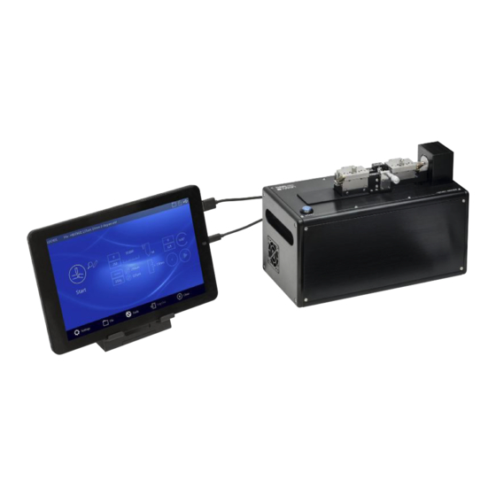
LDC401 & LDC401A Automated Cleavers Chapter 4: Set-up The other USB cable has one end that is USB Type A. Plug that end of that cable into the USB socket of the tablet. Plug the USB Type B plug into its socket on the back of the unit. -
Page 12: Chapter 5 The Tablet Controller
LDC401 & LDC401A Automated Cleavers Chapter 5: The Tablet Controller Chapter 5 The Tablet Controller The Tablet Controller provides a simple, easy to use interface for configuring, controlling and monitoring LDC401 series cleavers. Figure 6 Tablet Controller – LDC401 Main Screen A status bar at the top of the screen indicates the machine connected, the file currently open (if any) and status icons for file, access security and USB connection. -
Page 13: Chapter 6 Theory Of Cleaving
LDC401 & LDC401A Automated Cleavers Chapter 6: Theory of Cleaving Chapter 6 Theory of Cleaving The LDC401 and LDC401A automated fiber cleavers are designed for cleaving optical fibers with claddings from Ø80 µm up to Ø1.25 mm. To produce a flat cleave, the cleavers use a “tension-and-scribe” method, whereby an axial tension is first applied to the fiber followed by an automated Scribe Process utilizing a diamond Cleave Blade. -
Page 14: Chapter 7 Cleaving
LDC401 & LDC401A Automated Cleavers Chapter 7: Cleaving Chapter 7 Cleaving 7.1. Overview The LDC401 and LDC401A cleave fiber using the tension-and-scribe technique as follows: 1. A stripped fiber is secured in Fiber Holding Blocks (FHBs). 2. The left FHB moves to the left, tensioning the fiber. 3. -
Page 15: The Fiber Holding Blocks, Inserts, Lifting Levers, And Thumbscrews
LDC401 & LDC401A Automated Cleavers Chapter 7: Cleaving 3. When the fiber is cleaved, the cleaver senses the drop in tension and immediately draws the Cleave Blade back, the left FHB pulls further left to draw the cleaved fiber away from the waste piece, and the rotary stage returns to a level position. - Page 16 LDC401 & LDC401A Automated Cleavers Chapter 7: Cleaving In the event that you wish to use a fiber that is between insert sizes, refer to the chart in Section 10.1 to determine which inserts would be most suitable or use the Insert Selection tool in Tablet Controller. Fiber Holder Insert Side 1 Min/Max Side 2 Min/Max...
-
Page 17: Stripping The Fiber
LDC401 & LDC401A Automated Cleavers Chapter 7: Cleaving Thumbscrews Lift levers to permit lids to close fully Figure 12 Lifting Levers and Thumb Screws Thumbscrews on the FHB lids provide added clamping force for large diameter fibers (>400 µm) or for fibers with very slippery coatings requiring additional clamping force. -
Page 18: Loading The Fiber
LDC401 & LDC401A Automated Cleavers Chapter 7: Cleaving 7.5. Loading the Fiber To load the fiber for cleaving: 1. Make sure that the correct Cleave File (Fiber File) and/or process parameters are selected for the fiber to be cleaved (see Chapter 9). In the first instance the critical parameters can be estimated using the Auto Parameter Tool in the Tablet Controller. -
Page 19: Cleaving The Fiber
LDC401 & LDC401A Automated Cleavers Chapter 7: Cleaving 7.6. Cleaving the Fiber To cleave the fiber: 1. Confirm that the fiber is loaded properly and that both levers are raised. 2. Initiate the Cleave Process by pressing the blue START button on the unit or the START button on the Tablet Controller. -
Page 20: Unloading The Fiber
Remove any fibers and/or discards from the FHBs and cycle the power OFF then ON. The cleaver will initialize and attempt to run the homing process again. If any further difficulty is experienced, contact techsupport@thorlabs.com for assistance. Figure 16... -
Page 21: Changing The Fiber Holding Block Inserts
LDC401 & LDC401A Automated Cleavers Chapter 7: Cleaving 7.8. Changing the Fiber Holding Block Inserts Both the top and bottom FHB Inserts must be selected according to the diameter of the fiber being clamped. It is common to have a set of inserts for larger diameters in the left-hand FHB for clamping on the coating, than those in the right-hand FHB, which typically clamps on the cladding. - Page 22 LDC401 & LDC401A Automated Cleavers Chapter 7: Cleaving To change the bottom V-groove insert: Loosen the set screws accessible from the front of the FHB base using the 0.035” hex key included in the tool kit. Do NOT remove the set screws completely; one full turn counterclockwise should be sufficient to release the insert.
-
Page 23: Specialty Cleave Process
LDC401 & LDC401A Automated Cleavers Chapter 7: Cleaving 7.9. Specialty Cleave Process Two additional process capabilities are available on these cleavers. These processes are primarily utilized for specialty fiber cleaving such as microstructured fiber, highly stressed fibers (usually PM), or capillary tubing. The specialty fiber processes are used to improve end face quality but require the execution of additional steps. - Page 24 LDC401 & LDC401A Automated Cleavers Chapter 7: Cleaving The Micrometer Backstop acts as a backing for the fiber during the Cleave Process. When using the Micrometer Backstop, it is possible to reduce the tension applied to the fiber because the Micrometer Backstop will prevent the fiber from flexing when struck by the blade to produce a longer initial scribe.
-
Page 25: Chapter 8 Maintenance
LDC401 & LDC401A Automated Cleavers Chapter 8: Maintenance Chapter 8 Maintenance These cleavers are designed to provide trouble-free operation in a production environment provided that planned maintenance is performed as described below. Planned Maintenance Schedule Inspect and clean the Fiber Holding Blocks every shift. ... -
Page 26: Inspecting The Cleave Blade
LDC401 & LDC401A Automated Cleavers Chapter 8: Maintenance 8.2. Inspecting the Cleave Blade The diamond edge of the Cleave Blade should be inspected daily for debris and/or damage which may result in sub-optimal cleave performance. For easier inspection and cleaning, the Blade Service tool may be selected from the Tablet Controller tools (Section 9.5.4). -
Page 27: Re-Positioning The Cleave Blade
LDC401 & LDC401A Automated Cleavers Chapter 8: Maintenance 8.3. Re-Positioning the Cleave Blade Only a small portion of the Cleave Blade edge is used to scribe the fiber. If this local portion of the edge gets damaged, the blade can be re-positioned to a new “un-used” section. While the lifetime of a given section of the blade can be very long (greater than 5,000 cleaves), it is also very easy to damage the blade due to excessive lateral stresses (stresses perpendicular to the edge of the blade). -
Page 28: Replacing The Cleave Blade
LDC401 & LDC401A Automated Cleavers Chapter 8: Maintenance Figure 24 Adjusting the Height of the Cleave Blade 8.4. Replacing the Cleave Blade If the Cleave Blade is sufficiently damaged along its edge such that it cannot be re-positioned to an “un-used” section, then replacement is required. - Page 29 LDC401 & LDC401A Automated Cleavers Chapter 8: Maintenance Select the Blade Service tool function in the Tablet Controller. This function will move the Cleave Blade forward to the cleave position. Loosen the set screw in the top of the Cleave Arm one full turn counter-clockwise, using the 0.035″ hex key provided.
-
Page 30: Load Cell Calibration
The load cell calibration should be checked every year to ensure that accurate Cleave Tension is applied to the fiber and that optimal cleave angle and end-face quality is achieved. This task must be performed by a Vytran Thorlabs-certified technician. Page 26... -
Page 31: Chapter 9 Controlling The Ldc401 And Ldc401A
LDC401 & LDC401A Automated Cleavers Chapter 9: Controlling the LDC401 and LDC401A Chapter 9 Controlling the LDC401 and LDC401A The Tablet Controller provides a simple, easy to use interface for configuring, controlling and monitoring LDC401 series cleavers. The following sections contain a quick start guide followed by a more detailed view of the features and capabilities of the Tablet Controller. -
Page 32: Cleave Screen
LDC401 & LDC401A Automated Cleavers Chapter 9: Controlling the LDC401 and LDC401A In the edit / viewing screen, touch the value to enable the On-Screen-Keyboard and edit the value. Touch or X to return to the Parameter Select Screen. Figure 30 Parameter Edit Screen The parameter list indicates that an item has been changed by displaying a different icon... - Page 33 LDC401 & LDC401A Automated Cleavers Chapter 9: Controlling the LDC401 and LDC401A Once the left FHB lid is closed, the user is given extra time to close the right FHB lid. Pressing ‘Start’ will advance the LDC401 to the tension stage. Figure 32 Cleave Screen –...
- Page 34 LDC401 & LDC401A Automated Cleavers Chapter 9: Controlling the LDC401 and LDC401A Once tension is reached, the Cleave Peck Indicator is also displayed. Figure 35 Cleave Screen – Tension and Peck When the fiber is cleaved, the tension will drop to zero and the Cleave Peck Indicator remains on screen. The LDC will wait for the user to start unloading the fiber (raising the left FHB lid).
-
Page 35: Tablet Controller Online
LDC401 & LDC401A Automated Cleavers Chapter 9: Controlling the LDC401 and LDC401A Figure 38 Cleave Screen – Homing Once homing is complete, the Tablet Controller indicates it is ready to start the next cleave. Figure 39 Cleave Screen – Ready The Tablet Controller remains in the Cleave Screen for the convenience of the user. -
Page 36: Ldc Main Screen
LDC401 & LDC401A Automated Cleavers Chapter 9: Controlling the LDC401 and LDC401A The Tablet Controller provides an ‘offline’ mode in which files can be modified and uploaded later. 9.2.1. LDC Main Screen The LDC Main Screen, much like the Main Screen for any other Vytran PTR module, shares a common theme. It has a status bar, one or more control (action) buttons, a view / edit button to access parameters related to that control or action, a Widget (for displaying the most relevant current parameters) and a toolbar. -
Page 37: Settings
LDC401 & LDC401A Automated Cleavers Chapter 9: Controlling the LDC401 and LDC401A Figure 42 LDC Main Screen – Cleave Widget From bottom left to bottom right: Target tension Fiber cladding and jacket diameter Micrometer Backstop position Regular cleave/Sub-critical cleave ... -
Page 38: Password
LDC401 & LDC401A Automated Cleavers Chapter 9: Controlling the LDC401 and LDC401A Figure 45 Toolbar – Settings Screen From this screen the user can setup or enter a password, control user access permissions, enable or disable voice notifications, select the user interface language, view and manage communication ports. 9.3.1. -
Page 39: Access Permissions
LDC401 & LDC401A Automated Cleavers Chapter 9: Controlling the LDC401 and LDC401A Once the correct password has been entered (in this case 1234), it can be changed by touching the Change Password text to continue. Figure 47 Toolbar – Change Password Option Touch the Enter New Password box and enter the new password, repeat in the confirmation box. -
Page 40: Voice Notifications
Enable audible notifications in spoken language when a process has begun and whether it completed successfully or failed. Voice notifications will attempt to load an appropriate Text-To-Speech (TTS) voice for the current language selection. This requires a suitable (TTS) Voice has been installed. Contact Thorlabs / Vytran for more details. Figure 50 Toolbar –... -
Page 41: Language
LDC401 & LDC401A Automated Cleavers Chapter 9: Controlling the LDC401 and LDC401A Figure 51 Toolbar – Voice Notifications (Current Language – Chinese) 9.3.4. Language The user can select the preferred user-interface language. Language selection is independent of computer locale or computer language packs installed. Complete translations are available in English, French and Russian and Chinese, more will be available in the future. -
Page 42: Comm Ports
LDC401 & LDC401A Automated Cleavers Chapter 9: Controlling the LDC401 and LDC401A Figure 53 LDC Parameters Select in Russian 9.3.5. Comm Ports The Comm Ports screen lists all communications ports detected by Tablet Controller which can be useful when fault-finding a missing connection. Tablet Controller will normally auto-detect the correct USB serial Comm Port to communicate with the LDC. -
Page 43: Open File
LDC401 & LDC401A Automated Cleavers Chapter 9: Controlling the LDC401 and LDC401A 9.4.1. Open File Figure 55 Toolbar – File Open Screen In both File Open and Save File As screens, the existing files are listed in order of Most Recently Used (MRU). Any file that has been saved as a read-only file will display the small lock symbol next to the file name. -
Page 44: Tools
LDC401 & LDC401A Automated Cleavers Chapter 9: Controlling the LDC401 and LDC401A 9.5. Tools Each Vytran machine type has its own suite of tools, designed to simplify certain tasks. Some of the tools are common to multiple machine types, others are unique to just one. Touching Toolbar – Tools brings up the Tool Selection Screen. -
Page 45: Motor Control
LDC401 & LDC401A Automated Cleavers Chapter 9: Controlling the LDC401 and LDC401A 9.5.2. Motor Control The Motor Control window initially allows the user to select which motor to manipulate. On LDC401, these are left FHB, Cleave Blade and right rotation. On selecting one of these options, a generic motor control window opens. Figure 59 Tools –... -
Page 46: Blade Service
LDC401 & LDC401A Automated Cleavers Chapter 9: Controlling the LDC401 and LDC401A Note that distance between FHBs refers to the ‘Clamping Distance’ and the Fiber Modulus is its Young’s Modulus of Elasticity - typically 28 for SMF28. However for softer glass, 28 will be too high, and you should look up the modulus of rigidity. -
Page 47: Log Out
LDC401 & LDC401A Automated Cleavers Chapter 9: Controlling the LDC401 and LDC401A Figure 63 Tools – Insert Selector 9.6. Log Out When the user enters a password, the user is considered ‘logged in’ with full access permission. The Log Out button provides a quick method of returning to the normal access permission level. - Page 48 LDC401 & LDC401A Automated Cleavers Chapter 9: Controlling the LDC401 and LDC401A Pre-Cleave Advance + Blade Offset = the distance that the blade moves towards the fiber before entering the oscillation phase of its movement. The Tablet Controller provides both manual and Auto Parameter options for setting the Pre-Cleave Pre-Cleave Advance Advance.
-
Page 49: Parameter Limit
LDC401 & LDC401A Automated Cleavers Chapter 9: Controlling the LDC401 and LDC401A This parameter is used by the Insert Selection Tool to determine the optimum insert Coating Diameter choice for the left FHB. The coating diameter is also displayed in the Cleave Widget. Backstop Position is displayed in the Cleave Widget and provides a visual clue that Backstop Position the backstop should be set and its approximate value. -
Page 50: Setup Tips - Cleaving A New Fiber
Technical assistance is available from Vytran Thorlabs. If one is available, it is useful to observe the end face of the fiber with an Interferometer if developing a new process. -
Page 51: Chapter 10 Accessories
Bottom Inserts are required to operate the Cleaver. Available Inserts are described below, and the Insert Selection Guide in Section 10.1 should be used to select the appropriate Inserts for each holding block. Top Inserts The table below summarizes the top Fiber Holder Inserts that are available from Thorlabs. Side 1 Min/Max Side 2 Min/Max... - Page 52 LDC401 & LDC401A Automated Cleavers Chapter 10: Accessories Transfer Inserts, if desired, while the right Fiber Holding Block of the LDC401A is incompatible with the Transfer Inserts, due to the presence of the Rotation Stage. Transfer Side 1 Min/Max Side 2 Min/Max Vacuum Item # Insert...
- Page 53 LDC401 & LDC401A Automated Cleavers Chapter 10: Accessories Fiber Holder Insert Selection Chart Top Insert Item # VHA00 VHA05 VHA10 VHA15 VHA20 VHA25 VHA30 Accepted Diameter ≤320 400 µm 500 µm 750 µm 1000 µm 1250 µm 1500 µm 1750 µm 2000 µm 2250 µm 2500 µm...
- Page 54 The LFS4100 splicer and GPX series of glass processing stations require extra support for the fiber tips close to the heating filament for fibers with cladding diameters ≤550 µm. For this purpose, Thorlabs offers graphite tips with V-grooves that can be installed in the transfer Inserts. Available graphite tips are outlined in the table below.
-
Page 55: Chapter 11 Specifications
LDC401 & LDC401A Automated Cleavers Chapter 11: Specifications Chapter 11 Specifications Item # LDC401 LDC401A Flat Cleave Cleave Type Flat Cleave Angled Cleave up to 15° Cladding: Ø80 µm to Ø1.25 mm Accepted Fiber Sizes Buffer: Ø80 µm to Ø3.198 mm SM, PM, MM, Specialty Fibers Including Accepted Fiber Types Photonic Crystal Fiber (PCF) and Non-Circular Fiber, Capillary Tubes... -
Page 56: Chapter 12 Servicing And Troubleshooting
Note: Please keep the original packaging and pink anti-static bag that the unit came in. Reuse it if your system needs to be returned to Thorlabs for service or evaluation.The illustrations below show the correct way to re-pack the LDC401 or LDC401A. Please ensure that the bottom of the box is taped securely before re-packing the unit. If returning a malfunctioning unit for repair, we ask that you return the accessories with the unit in case one of the accessories happens to be the source of the problems. -
Page 57: Frequently Asked Questions
Parameter tool built into the Tablet Controller can provide a first estimate for the cleave parameters. If you have further questions, contact Thorlabs’ tech support at techsupport@thorlabs.com. Q: How do I know which Inserts I need to use with my fiber? Refer to the “Insert Selection Guide”... -
Page 58: Toubleshooting
LDC401 & LDC401A Automated Cleavers Chapter 12: Servicing and Troubleshooting 12.3. Toubleshooting Symptom Possible Cause Solution Fiber is not actually being held Lift levers because levers were not lifted Fiber is not actually being held Replace inserts with appropriately-sized because inserts are not Inserts appropriate for that fiber size Clean lower v-groove inserts and top... -
Page 59: Chapter 13 Regulatory
Waste Treatment is Your Own Responsibility If you do not return an “end of life” unit to Thorlabs, you must hand it to a company specialized in waste recovery. Do not dispose of the unit in a litter bin or at a public waste disposal site. -
Page 60: Chapter 14 Thorlabs Worldwide Contacts
LDC401 & LDC401A Automated Cleavers Chapter 14: Thorlabs Worldwide Contacts Chapter 14 Thorlabs Worldwide Contacts USA, Canada, and South America UK and Ireland Thorlabs, Inc. Thorlabs Ltd. 56 Sparta Avenue 1 Saint Thomas Place, Ely Newton, NJ 07860 Cambridgeshire CB7 4EX... - Page 62 www.thorlabs.com...
Need help?
Do you have a question about the Vytran LDC401 and is the answer not in the manual?
Questions and answers