Table of Contents
Advertisement
Quick Links
Advertisement
Table of Contents

Related Manuals for THORLABS Vytran LFS4100


Summary of Contents for THORLABS Vytran LFS4100
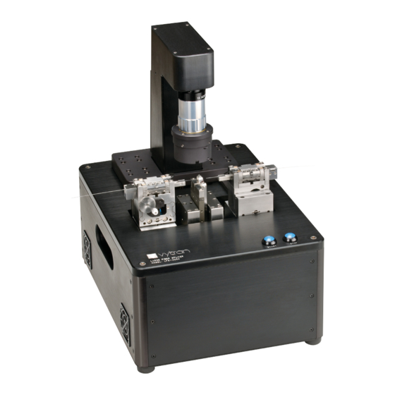
- Page 1 LFS4100 Fiber Splicer User Guide...
-
Page 2: Table Of Contents
LFS4100 Table of Contents Chapter 1 Warning Symbol Definitions ..................1 Chapter 2 Safety ..........................2 Chapter 3 Description ........................3 3.1. Introduction ........................3 3.2. Filament Fusion Splicing ....................3 3.3. Features ........................... 3 3.4. LFS4100 System and Accessories ................4 3.5. ... - Page 3 7.5. RMA Process ......................... 34 Chapter 8 Fiber Holder Insert Selection Guide ................35 Chapter 9 Specifications ........................ 38 9.1. Electrical Power ......................38 9.2. Gas Supply ........................38 Chapter 10 Regulatory ........................39 Chapter 11 Thorlabs Worldwide Contacts ..................40...
-
Page 4: Chapter 1 Warning Symbol Definitions
LFS4100 Chapter 1: Warning Symbol Definitions Chapter 1 Warning Symbol Definitions Below is a list of warning symbols you may encounter in this manual or on your device. Symbol Description Direct Current Alternating Current Both Direct and Alternating Current Earth Ground Terminal Protective Conductor Terminal Frame or Chassis Terminal Equipotentiality... -
Page 5: Chapter 2 Safety
LFS4100 Chapter 2: Safety Chapter 2 Safety WARNING The filament in the LFS4100 furnace generates intense light when it is in operation. It is strongly advised that the user NOT look directly at it during splicing or tapering operations. CAUTION: HOT SURFACE The furnace gets extremely hot when the filament turns on. -
Page 6: Chapter 3 Description
3.2. Filament Fusion Splicing Thorlabs’ unique filament fusion technology provides a consistent, reliable method of making high-strength, low- loss splices. Precision control of the fusion process is achieved by purging the splice region with an inert gas and using a resistive graphite or iridium filament to supply the thermal input necessary for fiber fusion. Because the fusion heat source is isolated for the environment, filament fusion splicing is not dependent upon ambient conditions. -
Page 7: Lfs4100 System And Accessories
LFS4100 Chapter 3: Description 3.4. LFS4100 System and Accessories 1. LFS4100: Splicing system 2. Desktop Computer: Dell 3. External Power Supply: Dual voltage power supply and cable 4. Vacuum Pump: Vacuum pump LV-125A for vacuum V-groove (alternative model supplied for 230V markets.) 5. -
Page 8: External Workstation Connections
LFS4100 Chapter 3: Description 3.5.1. External Workstation Connections The splicer workstation is the main component of the LFS4100 system. The PC and gas supply, as well as peripheral components such as an optical power meter, are connected to its back panel as illustrated below. Figure 3 Splicing Workstation Connections Power:... -
Page 9: Fiber Holding Blocks
A variety of fiber holder inserts are available for different fiber diameters. To see the available fiber holder inserts, see the selection chart in Chapter 8. In addition to the standard sizes, custom inserts may be specially designed for various applications. Contact Thorlabs for more information. Figure 5 Fiber Holder Inserts 3.5.4. -
Page 10: Splice Head
Splice Head with Filament Assembly 3.5.6. Filament Assembly Thorlabs supplies filaments as part of a filament assembly, as shown in the Figure 8. These assemblies contain a graphite or iridium filament within a protective shroud. One filament assembly (sold separately) is required to operate the LFS4100 fusion splicer. -
Page 11: Filaments
LFS4100 Chapter 3: Description Figure 8 Filament Assembly 3.5.7. Filaments The filaments are omega-shaped resistive heaters. Proper filament selection and splice parameters are essential for optimum splice performance. Graphite filaments are capable of achieving the high temperatures necessary for splicing large-diameter fibers, making them ideal for most applications. Iridium filaments operate at slightly lower temperatures than graphite filaments, making these ideal for working with softer glass fibers. -
Page 12: Mirror Tower
LFS4100 Chapter 3: Description 3.5.8. Mirror Tower The mirror tower holds two sets of mirrors and an LED. The first set of mirrors makes it possible to view the sides of the fibers. They provide the front view and back view, respectively. The second set of mirrors makes it possible to view the ends of the fibers. -
Page 13: Chapter 4 Set-Up
LFS4100 Chapter 4: Set-Up Chapter 4 Set-Up 1. Unpack the desktop computer and set it up using the included instructions from the computer manufacturer. If the operator is right handed, the computer should be set up to the right of the operator. If the operator is left handed, the computer should be set up to the left of the operator. - Page 14 LFS4100 Chapter 4: Set-Up 7. Connect the gas line to the back of the LFS4100. Make sure to push the gas line all the way into the fitting. To check if the line is connected properly, pull lightly on it to make sure it is held by the fitting. 8.
-
Page 15: Chapter 5 Software Interface
LFS4100 Chapter 5: Software Interface Chapter 5 Software Interface The software interface involves a graphical user interface, or GUI, and an SQL database. The GUI is the main window when working on the LFS4100. It has different menus and toolbars that are explained in this chapter. The buttons are described from top to bottom. -
Page 16: View
LFS4100 Chapter 5: Software Interface Database Options: Enables or disables the database and resets the database. The database has preconfigured settings that should not be altered. Engineer Mode : Not yet activated Engineer Password: Not yet activated. Exit: Close the GUI. 5.1.2. - Page 17 LFS4100 Chapter 5: Software Interface Toolbars: The Process Toolbar, Macro Toolbar, Quick-Open File Toolbar, and Camera Toolbar can be modified through the Toolbars menu Edit Processes Bar: Allows the user to define which process will be shown on the Processes Toolbar for quick usage.
- Page 18 LFS4100 Chapter 5: Software Interface Edit Quick-Open File Bar : Allows the user to choose which files appear on the Quick-Open File Toolbar. Users can add or remove files from this window. Camera Bar Properties : Allows the user to edit the properties of each fiber view provided by the camera.
- Page 19 LFS4100 Chapter 5: Software Interface CCD Camera: The view settings within this window allow the user to turn on and off all the cursors on the screen. Options on the Camera Settings tab are pre-set; the user should not change them. Mechanical : The Mechanical menu includes...
- Page 20 LFS4100 Chapter 5: Software Interface Argon Flow Rates : Three argon flow rate options can be set using this window. The Purge and Background settings are controlled in this window, while the argon flow rate for the splice is set in the Splice Properties window. Cleave Angle Limits: The system can measure the cleave angle of the fibers before...
-
Page 21: Splice
LFS4100 Chapter 5: Software Interface 5.1.4. Splice The different splice processes and parameters can be adjusted using the Splice menu. More details about these options will be discussed in Chapter 6. 5.1.5. Reset The Reset menu allows the user to initialize, stop, and reset the LFS4100 5.1.6. -
Page 22: Command Bar
LFS4100 Chapter 5: Software Interface 5.2. Command Bar The Command bar allows the user to directly enter a command to perform motion control using the system’s stepper motors. In the example above, the third motor (lens position) is moved forward by 200 steps. Commands are entered into the white window. -
Page 23: Quick-Open File Bar
: This command saves the parameters currently in use to an XML file that can be accessed later. If you are using an XML file created by Thorlabs, it is recommend that you perform a Save As command so that the standard file can be referenced in the future. -
Page 24: Camera Image
: This button estimates the loss in a splice based on the appearance of the cores in the splice region. For more accurate estimation, you need to have the correct calibration file. Please contact Thorlabs for more assistance One Button Process: This executes the Splice Routine found under Splice, Splice Process Editor, which generally includes alignment and gapping. -
Page 25: Movement Control Bar
LFS4100 Chapter 5: Software Interface 5.9. Movement Control Bar The seven boxes in the Movement Control Bar permit the user to move the fiber holding blocks and splice head at will by clicking on the forward and back arrows. The radio buttons labeled “Fine,” “Medium,” and “Coarse” allow the user to decide how much motion should occur with each click of an arrow. -
Page 26: Status Bar
LFS4100 Chapter 5: Software Interface 5.10. Status Bar Status Window : This window indicates the status of the unit. When the bottom bar is green and the window reads “Ready,” the unit is ready to execute new commands. When the top bar is red, the unit is not responding and is either busy or needs to be initialized Argon Window: If the user double-clicks the argon window, the argon flow rate is... -
Page 27: Chapter 6 Fusion Splicing
LFS4100 Chapter 6: Fusion Splicing Chapter 6 Fusion Splicing Fusion splicing is a process of joining two optical fibers end-to-end using heat. The goal is to fuse the two fibers together in such a way that light passing through the fibers is not scattered or reflected back by the splice, and the splice and the region surrounding it are almost as strong as the virgin fiber itself. - Page 28 LFS4100 Chapter 6: Fusion Splicing It is important to check the following items before beginning the splicing process: Splice Power: This is the amount of power the filament will receive during the splice. Check the filament power displayed in the Splice Parameters window. To change the splice power, select the Power box and enter the desired splice power in watts.
-
Page 29: Multiple-Stage And Multiple File Splicing
LFS4100 Chapter 6: Fusion Splicing 6.2. Multiple-Stage and Multiple File Splicing For certain special applications, the system can run several splice steps in a sequence. Mult-stage splice options can be accessed from Menu Bar, Splice, Splice Parameters, Multiple-Stage Splice. Users can set up all the parameters for each splice step and add or remove splice steps in this window. -
Page 30: Fiber Alignment
LFS4100 Chapter 6: Fusion Splicing 6.3. Fiber Alignment WARNING Similarly, the camera tower can generate a fair amount of force as it moves forward and back, and up and down. It is strongly advised that users NOT put their fingers between it and the furnace or mirror tower while the machine is in operation. -
Page 31: Active Xy Alignment
All of this data is saved into a file called “power_spectrum.txt,” which is appended with data from every splice. Data from at least 20 splices is required for a sensible calibration. The “power_Spectrum.txt” file should be sent to Thorlabs to generate the calibration coefficients. 6.5. -
Page 32: System Malfunction
LFS4100 Chapter 6: Fusion Splicing 6.6. System Malfunction If the system detects a critical problem during any operation, the Failure window will be shown and request input from the operator for further operation. Abort: This button ends the current one button process. -
Page 33: Chapter 7 Maintenance
LFS4100 Chapter 7: Maintenance Chapter 7 Maintenance 7.1. Fiber Holding Block Maintenance The fiber holding blocks must be cleaned periodically to ensure accurate fiber positioning. It is also sometimes necessary to change fiber holding block inserts to accommodate different fiber sizes. 7.1.1. -
Page 34: Filament Replacement Procedure
LFS4100 Chapter 7: Maintenance 7.2. Filament Replacement Procedure Switch the LFS4100 on and initialize. Home the Fiber holding blocks by clicking on the “FHB Home” macro button. Home the lens by clicking on the “Lens Home” macro button. ... - Page 35 LFS4100 Chapter 7: Maintenance Fit and secure the 2 screws that fasten the filament body to the furnace. Do not over tighten. Use a torque wrench set to 6 lb-in. Re-fit the stainless steel cover plates and fasten. ...
-
Page 36: Cleaning The Mirror
LFS4100 Chapter 7: Maintenance To home the splice head vertically, press the “Filament Home” macro button. Then, type 5motorto (14 @14) into the command window and hit “Enter.” View the image on the screen to make sure the fiber is still centered in the filament. -
Page 37: Measuring And Setting The Argon Flow Rates
To return the unit for service, contact Thorlabs. Visit https://www.thorlabs.com/locations.cfm for contact information. When returning the product to Thorlabs, please use the original packaging and pink anti-static bag that the unit came in. The illustrations below show the correct way to re-pack the LFS4100. Please ensure that the bottom of the box is taped securely before re-packing the unit. -
Page 38: Chapter 8 Fiber Holder Insert Selection Guide
LFS4100 Chapter 8: Fiber Holder Insert Selection Guide Chapter 8 Fiber Holder Insert Selection Guide Top Inserts: The LFS4100 fusion splicer requires fiber holder inserts to be placed in the fiber holding blocks in order to clamp the fibers during the splicing process. Fiber holder top inserts sit in the lid of the fiber holding blocks and come in a variety of groove sizes. - Page 39 LFS4100 Chapter 8: Fiber Holder Insert Selection Guide Fiber Holder Bottom Inserts for larger cladding or buffer diameters (indicated with Item #'s starting with VHE) come in single-sided and double-sided versions; the specified fiber diameter (in µm) is engraved on the part. These bottom inserts can also be used in the FPS300 Fiber Preparation Station, LDC Series of Fiber Cleavers, and GPX Glass Processing Systems.
- Page 40 LFS4100 Chapter 8: Fiber Holder Insert Selection Guide VHA00 VHA05 Top Insert Item # VHA00 VHA10 VHA15 VHA20 VHA25 VHA30 VHB00 VHB05 Accepted Diameter ≤320 µm 400 µm 500 µm 750 µm 1000 µm 1250 µm 1500 µm 1750 µm 2000 µm 2250 µm 2500 µm 3000 µm (Nominal) Bottom Accepted...
-
Page 41: Chapter 9 Specifications
Thorlabs supplies a high-purity PTFE gas line and a large gas regulator with the LFS4100. These are for use with a large gas tank (not supplied) which has a CGA-580 output port. Zero grade Argon gas with purity of > 99.999% is recommended;... -
Page 42: Chapter 10 Regulatory
Waste Treatment is Your Own Responsibility If you do not return an “end of life” unit to Thorlabs, you must hand it to a company specialized in waste recovery. Do not dispose of the unit in a litter bin or at a public waste disposal site. -
Page 43: Chapter 11 Thorlabs Worldwide Contacts
LFS4100 Chapter 11: Thorlabs Worldwide Contacts Chapter 11 Thorlabs Worldwide Contacts For technical support or sales inquiries, please visit us at www.thorlabs.com/contact for our most up-to- date contact information. USA, Canada, and South America UK and Ireland Thorlabs, Inc. Thorlabs Ltd. - Page 44 www.thorlabs.com...
Need help?
Do you have a question about the Vytran LFS4100 and is the answer not in the manual?
Questions and answers