Table of Contents
Advertisement
Quick Links
Advertisement
Table of Contents

Related Manuals for THORLABS DTS50


Summary of Contents for THORLABS DTS50
- Page 1 DTS50(/M) 50 mm Translation Stage User Guide Original Instructions...
-
Page 2: Table Of Contents
2.4 Transportation ..................12 2.5 Operation ....................12 2.6 Dimensions ................... 13 2.6.1 DTS50(/M) ......................13 Chapter 3 Specifications ................14 3.1 Specifications ..................14 3.2 Parts List ....................14 Chapter 4 Thorlabs Worldwide Contacts ........... 15 HA0339T Rev A Apr 2015... -
Page 3: Chapter 1 Safety
Chapter 1 Safety 1.1 Safety Information For the continuing safety of the operators of this equipment, and the protection of the equipment itself, the operator should take note of the Warnings, Cautions and Notes throughout this handbook and, where visible, on the product itself. The following safety symbols may be used throughout the ha ndbook and on the equipment itself. -
Page 4: Introduction
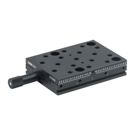
Chapter 2 Overview Introduction The DTS50(/M) dovetail translation stage is an entry-level positioner for use in general purpose positioning applications. It provides a travel range of 50 mm (2”), with 1 mm (0.04") travel per revolution of the adjuster. The design uses a precision-rolled M6 x 1.0 mm pitch leadscrew for smooth linear positioning along the entire range of... -
Page 5: Multi-Axis Configurations
Dowels are included with the purchase of each stage so th at perpendicularity between the two tra nslation directions is ma intained. See Section 3.2.5. and Section 3.2.6. for more details. Fig. 2.2 DTS50 series linear long travel stage – typical XY configuration... - Page 6 Chapter 2 Fig. 2.3 DTS50 stage – typical XYZ configuration HA0339T Rev A Apr 2015...
-
Page 7: Chapter 2 Installation
3.2 Mounting 3.2.1 General The DTS50 stage can be mounted directly to the work surface as shown in Section 3.2.3. For additional versitility, a base plate and angle bracket are available for use in horizontal or vertical mounting configurations - see Section 3.2.4. to Section 3.2.6. -
Page 8: Locking Mechanism
Chapter 3 3.2.2 Locking Mechanism The stage is shipped with a plate fitted to th e side, which locks the carriage during transit, and in applications where accidental adjustment is undesirable. The locking screw on these plates should be loosened before the stage is used as shown below. Loosen this screw before use Fig. -
Page 9: Fitting The Spacer Plate
DTS50 50 mm Translation Stage 3.2.4 Fitting the Spacer Plate A 5 mm (DTSA01) and a 10 mm (DTSA02) spacer plate are available to raise the height of the top surface to 25 mm or 30 mm respectively. To fit a spacer plate, refer to Fig. 3.3 and proceed as follows: 1) Adjust the actuator to position the moving carriage such that the mounting holes in the base are clearly visible through the holes in the top plate. -
Page 10: Building An Xy Configuration
Chapter 3 3.2.5 Building an XY Configuration Bolt the X-axis stage to the work surface as detailed in Section 3.2.3. or Section 3.2.4. then, referring to Fig. 3.4, proceed as follows:. Fig. 3.4 Building an XY Configuration 1) Fit the dowels supplied to the top plate of the lower stage. 2) Adjust the actuator to position the moving carriage of the upper stage such that the mounting holes in the base are clearly visible through the holes in the top plate. -
Page 11: Adding A Vertical (Z) Axis
DTS50 50 mm Translation Stage 3.2.6 Adding a Vertical (Z) Axis Assemble an X or XY configuration as detailed in Section 3.2.3. to Section 3.2.5. then, referring to Fig. 3.5 proceed as follows: 1) Fit the dowels supplied, into the moving platform on the lower stage assembly. -
Page 12: Mounting Equipment To The Stage
Chapter 3 5) Adjust the actuator to position the moving carriage of the vertical stage such that the mounting holes in the base are clearly visible through the holes in the top plate. 6) Fit the ve rtical-axis stage i nto place ensuring that the dowels fitted at item (4) locate correctly into the holes in the back surface of the angle bracket. -
Page 13: Dimensions
DTS50 50 mm Translation Stage 3.6 Dimensions 3.6.1 DTS50(/M) All Dimensions in mm (inches) 25.0 Pitch Typical (1.0”) M6 x 1 (1/4”-20) 17 Positions 12.5 Max Penetration Depth 7 mm (0.275”) (0.5”) Ø 3.0 (0.118”) Holes for Alignment Pins (2 Positions) 68.0... -
Page 14: Chapter 3 Specifications
Chapter 4 Specifications 4.1 Specifications Parameter Value Travel Range 50 mm Horizontal Load Capacity 40 kg (88 lb) Vertical Load Capacity 10 kg (22 lb) Top Surface Parallelism 1200 µRad Angular Deviation ±300 µRad Staightness Horizontal ±15.00 µm Vertical ±7.00 µm Stiffness Pitch 150.00 µRad/Nm Yaw 460.00 µRad/Nm... -
Page 15: Chapter 4 Thorlabs Worldwide Contacts
Chapter 5 Thorlabs Worldwide Contacts For technical support or sales inquiries, please visit us at www.thorlabs.com/contact for our most up-to-date contact information. USA, Canada, and South America UK and Ireland Thorlabs, Inc. Thorlabs Ltd. sales@thorlabs.com sales.uk@thorlabs.com techsupport@thorlabs.com techsupport.uk@thorlabs.com Europe Scandinavia... - Page 16 www.thorlabs.com...
Need help?
Do you have a question about the DTS50 and is the answer not in the manual?
Questions and answers