
Subscribe to Our Youtube Channel
Related Manuals for THORLABS BC207UV


Summary of Contents for THORLABS BC207UV
- Page 1 BC207UV(/M), BC207VIS(/M), and BC210CU(/M), BC210CV(/M) with M2MS(-AL) Camera Beam Profiler User Guide 2023...
- Page 2 Version: Date: 14-Aug-2023 Copyright © 2023 Thorlabs...
-
Page 3: Table Of Contents
Chapter 2 Introduction Chapter 3 Ordering Codes and Accessories Requirements Getting Started Chapter 4 Parts List BC207UV(/M) and BC207VIS(/M) Parts List BC210CU(/M) and BC210CV(/M) Operation Instructions Chapter 5 Operating Elements 5.1.1 BC207 and BC210C Series 5.1.1.1 Operating Elements BC207 Series 5.1.1.2 Operating Elements BC210C Series... - Page 4 BC207 and BC210C Series Camera Beam Profiler 5.4.1.4 Windows Menu 5.4.1.5 View Menu 5.4.1.6 Help Menu 5.4.2 Tool Bar 5.4.3 Status Bar 5.4.4 Save Settings 5.4.5 Beam Settings 5.4.5.1 Optical Setup 5.4.5.1.1 Wavelength 5.4.5.1.2 Attenuation 5.4.5.1.3 Power Correction 5.4.5.1.4 Ambient Light Correction 5.4.5.1.5 Intensity Threshold 5.4.5.2 Beam Profiler Information...
- Page 5 BC207 and BC210C Series Camera Beam Profiler 5.4.6.7 Tuning View 5.4.6.8 Beam Overlapping 5.4.6.9 Plots 5.4.6.9.1 Plot Positions 5.4.6.9.2 Plot Power 5.4.6.9.3 Plot Diameters 5.4.6.9.4 Plot Gaussian Fit 5.4.6.9.5 Plot Orientation 5.4.6.9.6 Plot Environment Data 5.4.6.9.7 Beam Stability Measurement with the Beam Profiler 5.5.1 Operating the Instrument 5.5.2...
- Page 6 Write Your Own Application Chapter 6 32 bit Operating System 64 bit Operating System Specifications BC207x and BC210Cx Chapter 7 Dimensions BC207UV(/M) and BC207VIS(/M) Dimensions BC210CU(/M) and BC210CV(/M) Specifications Filter Wheel Wavelength Response Power Ranges Specifications M2MS Extension Sets Chapter 8...
- Page 7 BC207 and BC210C Series Camera Beam Profiler Bessel Fit 13.7 Certifications and Compliances Chapter 14 Warranty and RMA Information Chapter 15 Return of Devices 15.1 WEEE Policy 15.2 Manufacturer Address Chapter 16 Copyright and Exclusion of Liability Chapter 17 Thorlabs Worldwide Contacts Chapter 18...
-
Page 8: Chapter 1 Safety
This precision device is only serviceable if returned and properly packed into the complete original packaging including the cardboard inserts. If necessary, ask for replacement packaging. Refer servicing to qualified personnel! Changes to this device cannot be made nor may components not supplied by Thorlabs be used without written consent from Thorlabs. Attention... - Page 9 Be sure to pay strict attention to the safety recommendations of the appropriate laser safety class, as stated for the used light source. The device is a class 1 laser sources. © 2023 Thorlabs Page 2 Rev: 8.2, 14-Aug-2023...
-
Page 10: Chapter 2 Intended Use
3. The Thorlabs products described in this document are not intended nor warranted for usage in Military Applications. -
Page 11: Chapter 3 Introduction
This includes a TTL input for triggered pulse detection of signals. The BC207 and BC210C series camera beam profilers can be purchased in an imperial version (BC207UV, BC207VIS, BC210CU, or BC210CV) and in a metric version (BC207UV/M, BC207VIS/M, BC210CU/M, or BC210CV/M). -
Page 12: Requirements
The requirements for using a PC to operate the BC207 and BC210C Series Camera Beam Profilers are given below. The BC207 Series requires Thorlabs Beam Software Version 8.0 or higher and the BC210C Series requires Version 9.0 or higher. Please find the BEAM Software for download from the... -
Page 13: Parts List Bc207Uv(/M) And Bc207Vis(/M)
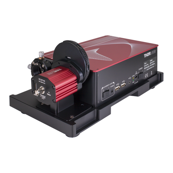
5.1.1 BC207 and BC210C Series 5.1.1.1 Operating Elements BC207 Series The components of the BC207UV are labeled in the image below. Aside from the mounting thread, BC207UV and BC207UV/M are identical. BC207VIS and BC207VIS/M outer dimensions and components look identical to BC207UV and BC207UV/M. BC207VIS(/M) differs in the mounted filters and the protection glass. - Page 14 BC207 and BC210C Series Camera Beam Profiler Chapter 5 Operation Instructions BC207UV MTN026962-D02 Page 7...
-
Page 15: Operating Elements Bc210C Series
The components of the BC210CU are labeled in the image below. Aside from the mounting thread, BC210CU and BC210CU/M are identical. BC210CV and BC210CV/M outer dimensions and components look identical to BC210CU and BC210CU/M. BC210CV(/M) differs in the mounted filters and the protection glass. BC210CU © 2023 Thorlabs Page 8 Rev: 8.2, 14-Aug-2023... -
Page 16: Filter Wheel
Chapter 5 Operation Instructions 5.1.1.3 Filter Wheel The Thorlabs BC207UV(/M), BC207VIS(/M), BC210CU(/M) and BC210CV(/M) Camera Beam Profilers are equipped with a filter wheel containing six different neutral density (ND) optical attenuation filters. The filter wheel is designed to quickly and easily adapt the light source power to a power level within the dynamic range of the CMOS camera. - Page 17 NE40B 40 dB UV Absorptive ND Filter, 400nm - 650 nm These filters are provided for use near the 400 nm upper wavelength range of the BC207UV(/M) or BC210CU(/M). The Model BC207VIS(/M) and BC210CV(/M) is equipped with six absorptive neutral density (ND) filters made from glass.
- Page 18 BC207 or BC210C Series Beam Profiler. In this case additional means for external beam attenuation in front of the beam profiler are required. The prism based Thorlabs ATT30x laser beam attenuators are particularly suitable as they preserve the polarization, size, and shape of the beam.
-
Page 19: Change Filter Wheel
Chapter 5 Operation Instructions 5.1.1.4 Change Filter Wheel The Thorlabs BC207UV(/M), BC207VIS(/M), BC210CU(/M), and BC210CV(/M) Camera Beam Profilers are equipped with a filter wheel containing six different neutral density (ND) optical attenuation filters. In case of spatial constraints, the filter wheel can be removed. - Page 20 BC207 and BC210C Series Camera Beam Profiler Chapter 5 Operation Instructions 4. Remove the ND filter. Please handle the filter carefully. Always wear gloves when handling filters, or touch the filter with a lint-free cloth. 5. Turn the filter wheel so that the grip recess is positioned above the first lower screw in order to remove the filter wheel completely with an Allen key, for example BD-1/16.
- Page 21 9. Now the filter wheel assembly can be removed from the camera housing. The camera's cover glass should not be touched. 10. To reattach the filter wheel, the steps must be performed in reverse order. © 2023 Thorlabs Page 14 Rev: 8.2, 14-Aug-2023...
-
Page 22: Status Led
The appropriate BNC (for BC207 Series) or SMA (for BC210C Series) connector to connect to a trigger out of a laser driver is located on the back side of the instrument body, see the chapter Operating Elements BC207UV(/M) and BC207VIS(/M) BC210CU(/M) and BC210CV(/M) . More... -
Page 23: Mounting Bc207 Series
On the bottom side of the BC207 Series Camera Beam Profilers, a mounting thread is provided. All metric models have M6 x 1 mm threads while the imperial models feature a 1/4"-20 thread. Mount the BC207UV(/M) or BC207VIS(/M) Camera Beam Profiler to your optical system using a Thorlabs post,... -
Page 24: Mounting Bc210C Series
BC207 and BC210C Series Camera Beam Profiler Chapter 5 Operation Instructions 5.1.1.9 Mounting BC210C Series Post Mounting and Sensor Position On the bottom and left side of the BC210C Series Camera Beam Profilers, a mounting thread is provided. All metric models have M6 x 1 mm threads while the imperial models feature a 1/4"-20 thread. -
Page 25: Camera Beam Profiler Series With M2Ms Extension Set
BC207 and BC210C Series Camera Beam Profiler Chapter 5 Operation Instructions Mount the BC210CU(/M) or BC210CV(/M) Camera Beam Profiler to your optical system using a Thorlabs post, post holder and a base or clamping fork. Sensor Position on BC210CU(/M) and BC210CV(/M) The sensor is centered with respect to the mounting thread holes on the bottom of the device. -
Page 26: Mounting Bc207 Series On M2Ms(-Al)
Chapter 5 Operation Instructions 5.1.2.2 Mounting BC207 Series on M2MS(-AL) Please use the mounting adapter for BC207 Series to M2MS in order to mount the BC207UV(/M) or BC207VIS(/M) beam profiler to the M2MS Measurement Extension. For a mounting adapter for BC207 onto a preexisting M2MS Extension Set, please contact Thorlabs. - Page 27 Chapter 5 Operation Instructions 4. Secure the adapter with the two enclosed M4 x 0.7 Cap Screw onto the M2MS Measurement Extension. The BC207UV(/M) or BC207VIS(/M) is now securely mounted to the M2MS Measurement Extension. © 2023 Thorlabs Page 20...
-
Page 28: Mounting Bc210C Series On M2Ms(-Al)
BC210CV(/M) beam profiler to the M2MS Measurement Extension. For a mounting adapter for BC210C onto a preexisting M2MS Extension Set, please contact Thorlabs. 1. Place the BC210C Series device onto the mounting adapter for the BC210C Series such that the dowel pins on the adapter fit into the holes for the dowel pins on the BC210C Series device. - Page 29 M2MS. 4. Secure the adapter with the two enclosed M4 x 0.7 Cap Screw onto the M2MS Measurement Extension. The BC210CU(/M) or BC210CV(/M) is now securely mounted to the M2MS Measurement Extension. © 2023 Thorlabs Page 22 Rev: 8.2, 14-Aug-2023...
-
Page 30: Setup Bc207 And Bc210C Series
The Beam Software can be downloaded from the Thorlabs website: http://www.thorlabs.com/software_pages/ViewSoftwarePage.cfm?Code=Beam Please check for updates to the Thorlabs Beam Software and always use the latest Software version. The Beam software versions 9.0 or higher support the BC210C beam profiler series. Software versions below version 9.0 do not support the BC210C Series. -
Page 31: Connection To The Pc
· Windows Security will ask your confirmation to install the Thorlabs USB driver. · You may check the box "Always trust software from "Thorlabs GmbH".This will shorten the installation. However, if you do not want to do that, please click the "Install" button. You will then be asked to confirm the installation of further Thorlabs software components. -
Page 32: Start The Application
BC207 and BC210C Series Camera Beam Profiler Chapter 5 Operation Instructions 5.3.3 Start the Application Click the "Programs" g "Thorlabs" g "Thorlabs Beam Application" entry, or simply click the appropriate icon added to your desktop. When the application is started, the following start screen appears:... - Page 33 Calculation Results, 2D Projection , 3D Profile. Otherwise, the arrangement of the last session (selected windows and their position) will be recovered. See the Child Windows chapter for a detailed description of each window. © 2023 Thorlabs Page 26 Rev: 8.2, 14-Aug-2023...
-
Page 34: The Graphics User Interface (Gui)
BC207 and BC210C Series Camera Beam Profiler Chapter 5 Operation Instructions 5.4 The Graphics User Interface (GUI) In this manual, the Beam Software is described based on a setup using a BC207VIS on the M2MS measurement extension for M measurements, connected to a PC running with OS Windows® 10. The application automatically adapts to the specifications of the BC207 or BC210C series beam profiler. -
Page 35: File Menu
If the 3D Profile window is opened, a screenshot of the 3D Profile is also included in the test report. See some detailed examples for data export in the Save Measurement Results chapter. © 2023 Thorlabs Page 28 Rev: 8.2, 14-Aug-2023... -
Page 36: Control Menu
BC207 and BC210C Series Camera Beam Profiler Chapter 5 Operation Instructions 5.4.1.2 Control Menu Use the first menu entry to start and pause the continuous operation of the Beam Profiler device including retrieving measurement data, performing calculations and displaying graphs and numerical results to the output windows. -
Page 37: Options Menu
If a certain color scale is required it is possible to create a custom color scale which can be loaded automatically by starting the application. To do so a few things need to be considered. When starting the software, the application loads valid *.lut files from the folder: ...\My Documents\Thorlabs\Thorlabs Beam\LUT © 2023 Thorlabs Page 30... - Page 38 BC207 and BC210C Series Camera Beam Profiler Chapter 5 Operation Instructions A valid *.lut file must fulfill the following criteria: · Ordinary text file with 9 columns and 256 rows · Values must be tab-separated · The first three columns have 256 entries ·...
- Page 39 The maximum number of data to be plotted Velocity 200 mm/s Translation speed of the stage Hot Pixel Correction Weak see chapter Hot Pixel Correction Language The language of the application can be selected. © 2023 Thorlabs Page 32 Rev: 8.2, 14-Aug-2023...
-
Page 40: Windows Menu
BC207 and BC210C Series Camera Beam Profiler Chapter 5 Operation Instructions 5.4.1.4 Windows Menu When the GUI is started the first time, the Default Workspace is opened. To close and open the windows, toggle the corresponding entry in the windows menu or via the Tool Bar An open child window can also be closed by clicking the S in the upper right corner of the child window. -
Page 41: Help Menu
Check for Update searches for available software updates. About Thorlabs displays device information and software versions details: If you have trouble with the software, please submit the version of the application to Thorlabs. This can help to resolve your problem. - Page 42 BC207 and BC210C Series Camera Beam Profiler Chapter 5 Operation Instructions Open the Device Connection dialog Restore Beam Settings panel (if unpinned or closed) Open the Display Settings panel Reset application settings to defaults Open child window 2D Projection Open child window 3D Profile Open child window Calculation Results...
-
Page 43: Status Bar
GUI main window, e.g., to a second PC monitor. When detached, the Pin icon in the upper right corner changes from . Click to this icon to bring the panel back into the GUI frame. The panel view can be customized easily by expanding or hiding topics. © 2023 Thorlabs Page 36 Rev: 8.2, 14-Aug-2023... - Page 44 BC207 and BC210C Series Camera Beam Profiler Chapter 5 Operation Instructions Beam Settings BC207 or BC210C Series Please read this section carefully and follow the setup instructions in order to maximize the accuracy of your measurements. MTN026962-D02 Page 37...
-
Page 45: Optical Setup
Beam Profiler instrument. The correct wavelength is important for accurate Beam Quality (M²) results as well. The available range is limited to 245 - 400 nm for BC207UV(/M) or BC210CU(/M) and 350 - 1100 nm for BC207VIS(/M) or BC210CV(/M), respectively. - Page 46 BC207 and BC210C Series Camera Beam Profiler Chapter 5 Operation Instructions 5.4.5.1.2 Attenuation The attenuation is given by the selection of the neutral density (ND) filter that is placed in front of the optical input. You can select a filter by rotating the filter wheel .
- Page 47 It is recommended to proceed with the ambient light correction after a 30 min warm-up time and repeat it if needed (e.g., ambient light conditions changed). Click the 'Start' button - the Ambient Light Correction Dialog appears. © 2023 Thorlabs Page 40 Rev: 8.2, 14-Aug-2023...
- Page 48 Click OK and close the Ambient Light Correction window. The Ambient Light Correction appears enabled, and the correction factor will be displayed. Note · Thorlabs Beam Software uses a unique approach for Ambient Light Correction - please see details in section Application Notes ·...
-
Page 49: Beam Profiler Information
Beam Profiler model, serial number, driver version, and firmware version are read out from the BC207 Series and BC210C Series instrument and cannot be changed. Beside general information, important sensor information is stated © 2023 Thorlabs Page 42 Rev: 8.2, 14-Aug-2023... -
Page 50: Camera Beam Profiler Parameter
BC207 and BC210C Series Camera Beam Profiler Chapter 5 Operation Instructions 5.4.5.3 Camera Beam Profiler Parameter This chapter contains a number of important camera settings that are accessible by the user. Please become familiar with the meaning of these controls in order to prevent improper adjustments which may lead to erroneous measurement results. - Page 51 Exposure time can range from 0.03 ms to 1000 ms (for BC207) or 500 ms (for BC210C) with a step width of 0.01 ms. Use the arrows in order to increase and decrease the exposure time stepwise. To enter a certain value just overwrite the present one. © 2023 Thorlabs Page 44 Rev: 8.2, 14-Aug-2023...
-
Page 52: Gain Control
Hot pixels may cause measurement errors, particularly in 4s measurements, which is important for M² beam quality measurements, and may impact the baseline definition during ambient light correction. Thorlabs Beam offers a hot pixel correction feature. To reduce or eliminate hot pixels from influencing the measurement, set the hot pixel correction to Weak, Moderate or Strong (maximum suppression of hot pixels). - Page 53 . Select "Software Trigger" in the Beam Settings panel. The ‘Software Trigger’ mode requires manual exposure control . An appropriate warning appears, if auto exposure is enabled: © 2023 Thorlabs Page 46 Rev: 8.2, 14-Aug-2023...
- Page 54 BC207 and BC210C Series Camera Beam Profiler Chapter 5 Operation Instructions To confirm, click "Yes" and enter the desired ‘Exposure Time ’ and the ‘Gain Factor ’ manually. Then define the ‘Min. Image Saturation’ level in %, that will be the software controlled brightness trigger level.
- Page 55 3) Switch the camera in the beam Software to the mode Single Pulse to activate the response to a hardware trigger. Please be aware that discrimination between single pulses is limited to about 10 Hz, highly dependent on the acquisition settings and the PC. © 2023 Thorlabs Page 48 Rev: 8.2, 14-Aug-2023...
- Page 56 BC207 and BC210C Series Camera Beam Profiler Chapter 5 Operation Instructions 5.4.5.3.6 Region of Interest The maximum Region of Interest (ROI) is 2448 x 2048 pixel (full size) and the smallest 32 x 32 pixel. The ROI depends on the settings for binning. With the ROI parameter, the user can define a subarea within the maximum available camera sensor surface for data acquisition.
-
Page 57: Calculation Parameter
It is advisable to set the camera ROI to the smallest feasible area instead of working with a large ROI and shrinking the Calculation Area afterwards. This will increase measurement speed. Six presets are provided to choose a Calculation Area. © 2023 Thorlabs Page 50 Rev: 8.2, 14-Aug-2023... -
Page 58: Clip Level
BC207 and BC210C Series Camera Beam Profiler Chapter 5 Operation Instructions Auto Rectangle: The software will analyze every image from the BC207 and BC210C Series automatically and determine the area in which a measurable amount of power is present. Areas with a power level lower than the clip level will be excluded from further calculations. - Page 59 1/e² =13.5 % of the peak intensity. Other values from 5% to 95% can be set by entering manually. Click on Default (1/e²) to set the default Clip Level of 13.5%. See Appendix Application Note details. © 2023 Thorlabs Page 52 Rev: 8.2, 14-Aug-2023...
-
Page 60: Hold Maximum
BC207 and BC210C Series Camera Beam Profiler Chapter 5 Operation Instructions 5.4.5.4.4 Hold Maximum The Hold Maximum feature is recommended for pulsed laser sources. In all subsequent scans for each pixel only the maximum values are stored, displayed and used for calculation. In comparison to the software trigger function of the Beam Software, Hold Maximum will only store... -
Page 61: Unit
Angle in degree with respect to the X axis, range -90° to +90°. 5.4.5.5 Plot Over Time Parameter The Beam Software allows to show different plots of beam measurements: Plot Positions Plot Power Plot Diameters Plot Gaussian Fit © 2023 Thorlabs Page 54 Rev: 8.2, 14-Aug-2023... -
Page 62: Translation Stage Control
"Translation Stage Control" and "M set" appear as the last two topics of the Beam Settings panel. The description in this section assumes a Thorlabs DDS100 Linear Translation Stage, as it is used in the M2MS Extension Set This panel allows the user to manually control the translation stage. - Page 63 Optical Setup The focus position is then determined based on internal M2MS parameters, the type of beam profiler, the focus offset and the determined focal length. © 2023 Thorlabs Page 56 Rev: 8.2, 14-Aug-2023...
-
Page 64: Child Windows
"Windows". Additional child windows are accessible through the menu bar The appearance of the Thorlabs Beam Software can be arranged according to your requirements and taste. All child windows can be re-sized and flexibly positioned. Here is an example of arranging some... -
Page 65: Projection
Displays the approximated Beam Ellipse in yellow color. The Ellipse ellipse is drawn corresponding to fitted or unfitted numerical data. See Beam Settings to enable/disable the ellipse fit. © 2023 Thorlabs Page 58 Rev: 8.2, 14-Aug-2023... - Page 66 BC207 and BC210C Series Camera Beam Profiler Chapter 5 Operation Instructions Toolbar Icon Associated Action The distance measurement editor opens a table beside the projection image. When drawing lines into the projection image, Distance Measurement Mode the distance is inserted into the table. A maximum of 10 distances can be drawn.
- Page 67 Settings, Unit ), the origin of the coordinate system is the selected reference position. Horizontal axis is X and vertical axis is Y. Both axes are also labeled on the Beam Profiler housing. © 2023 Thorlabs Page 60 Rev: 8.2, 14-Aug-2023...
-
Page 68: Profile
BC207 and BC210C Series Camera Beam Profiler Chapter 5 Operation Instructions 5.4.6.2 3D Profile The 3D Profile illustrates the power density distribution of the measured optical beam. Whereas the beam's cross-section is parallel with the X-Y-plane, the relative power intensity is shown in the Z direction (Pseudo 3D). -
Page 69: And Y Profiles
If "Autoscale to Peak" is enabled and the cross hair in 2D projection is fixed to peak, the measured curve shows relative intensities from 0 to 100%, where 100% denotes the maximum value in the selected row / column. © 2023 Thorlabs Page 62 Rev: 8.2, 14-Aug-2023... -
Page 70: Zooming And Panning Diagrams
BC207 and BC210C Series Camera Beam Profiler Chapter 5 Operation Instructions If the "Autoscale to Peak" function is disabled, the X and Y profiles will show a peak amplitude equal to the AD converter saturation. The amplitude of the Gaussian fit curve may be lower or even higher than the peak intensity of the measured curve. -
Page 71: Calculation Results
Click the marked green icon in the table in order to select or deselect parameters to be calculated and displayed. The fewer calculation results are enabled, the higher the speed performance of the software. © 2023 Thorlabs Page 64 Rev: 8.2, 14-Aug-2023... - Page 72 BC207 and BC210C Series Camera Beam Profiler Chapter 5 Operation Instructions Note · Even if the Gaussian and / or Bessel Fit calculations are disabled from display in the Calculation results panel, the appropriate fitted curves are still shown in the X and Y Profile windows, if enabled there.
- Page 73 · Add date, time stamp, index (optional) · Click "Save Calculations" Lock / Unlock Test Parameters; Load / Save Test Parameter Configuration. These functions are related to the configuration of the Pass / Fail Test functionality. © 2023 Thorlabs Page 66 Rev: 8.2, 14-Aug-2023...
- Page 74 BC207 and BC210C Series Camera Beam Profiler Chapter 5 Operation Instructions Sequential Saving This feature is used to save sequentially sets of the selected calculation results , e.g for a long term analysis. · Select the destination folder (see the preview pane). ·...
-
Page 75: Manual Vergence Measurement
The Beam Profiler is mounted so that it can slide along the beam propagation trace. This can be done using, for example, a Thorlabs M2 translation stage or a Thorlabs RLA Series of dovetail optical rails in combination with a series rail carrier and a post. - Page 76 BC207 and BC210C Series Camera Beam Profiler Chapter 5 Operation Instructions 2. The software calculates the beam width at Position 1. 3. Move the Beam Profiler, measure the distance again, enter the new distance into the box "Position icon. 2" and press the 2nd beam width at Position 2 is calculated and based on the entered distance change, the vergence angle in X and Y axes is displayed.
-
Page 77: Tuning View
· Peak Position X · Peak Position Y · Centroid Position X · Centroid Position Y · Ellipse Diameter min. · Ellipse Diameter max. · Beam Width Clip X · Beam Width Clip Y © 2023 Thorlabs Page 70 Rev: 8.2, 14-Aug-2023... - Page 78 BC207 and BC210C Series Camera Beam Profiler Chapter 5 Operation Instructions On the scales, the observed minimum and maximum values are shown as blue triangles. They can be reset using the buttons marked above. MTN026962-D02 Page 71...
-
Page 79: Beam Overlapping
The overlay method can be selected in the box "Composite Mode": Overlay "Plus" In "Plus" mode the intensities of the snap shot and the live image are added. This eases the adjustment particularly of regions with lower intensity. © 2023 Thorlabs Page 72 Rev: 8.2, 14-Aug-2023... - Page 80 BC207 and BC210C Series Camera Beam Profiler Chapter 5 Operation Instructions Overlay "Lighten" In "Lighten" mode, within the overlapping region only the "pixel" with higher intensity will be displayed; the intensities of the snapshot and the current beam are not added. Overlay "Difference"...
-
Page 81: Plots
BC207 and BC210C Series Camera Beam Profiler Chapter 5 Operation Instructions 5.4.6.9 Plots Thorlabs Beam Software offers several additional plot windows to show the beam behavior: Plot Positions Plot Power Plot Diameters Plot Gaussian Fit Plot Orientation Plot Environment Data Beam Stability All plot windows are accessible via the "Windows"... - Page 82 BC207 and BC210C Series Camera Beam Profiler Chapter 5 Operation Instructions 5.4.6.9.1 Plot Positions Toolbar: , Menu bar: Windows -> Plot Positions The positions of X and Y peak and of X and Y centroid positions can be displayed vs. time. Toolbar Icon Associated Action Save Diagram or Image: Opens a dialog box to specify the properties of the saved...
- Page 83 The total power measured by the Beam Profiler vs. time can be displayed. Note The power indication of Thorlabs Beam Profiler instruments is not calibrated vs. wavelength, it is based on a typical responsivity curve of the used sensor and the manually entered wavelength (see...
- Page 84 BC207 and BC210C Series Camera Beam Profiler Chapter 5 Operation Instructions 5.4.6.9.3 Plot Diameters Menu bar: Windows -> Plot Beam Diameters The Plot Diameters window displays the beam diameter over time as the user adjusts settings. This allows to easily monitor the behavior of the beam diameter. MTN026962-D02 Page 77...
- Page 85 Save Data: Opens a dialog box to specify the properties of the saved calculation data Clear all plots Show or Hide the grid in the diagram: Autoscale ON/OFF Show or hide the cursor © 2023 Thorlabs Page 78 Rev: 8.2, 14-Aug-2023...
- Page 86 BC207 and BC210C Series Camera Beam Profiler Chapter 5 Operation Instructions 5.4.6.9.5 Plot Orientation Menu bar: Windows -> Plot Orientation This window plots the orientation (in degrees) of the ellipse, see Calculation Results Toolbar Icon Associated Action Save Diagram or Image: Opens a dialog box to specify the properties of the saved diagram or image.
- Page 87 Save Data: Opens a dialog box to specify the properties of the saved calculation data Clear all plots Show or Hide the grid in the diagram Autoscale ON/OFF Show or hide the cursor © 2023 Thorlabs Page 80 Rev: 8.2, 14-Aug-2023...
- Page 88 BC207 and BC210C Series Camera Beam Profiler Chapter 5 Operation Instructions 5.4.6.9.7 Beam Stability Toolbar: , Menu bar: Windows g Beam Stability This feature allows the beam stability vs. time to be recorded in a very versatile way. Accumulated data are accessible from the graphic display by enabling several plots: Plots the trace of the centroid positions as a blue line Plots the most recent centroid position as yellow dot...
- Page 89 The maximum number of data points to be displayed, the handling of data points after reaching the maximum and the time interval between two displayed data points is set in the menu Beam Settings / Plot over Time Parameter © 2023 Thorlabs Page 82 Rev: 8.2, 14-Aug-2023...
-
Page 90: Measurement With The Beam Profiler
For accurate measurement results (power values, M² results) the correct wavelength must be entered. Thorlabs Beam Profiler instruments are not calibrated for power with respect to the wavelength. The power calculation is based on a typical responsivity curve of the used sensor and manually entered... - Page 91 The parameters to be calculated can be selected by clicking the icon in left upper corner the Calculation Results window. All contents of the child windows including available options are explained in chapter Child Windows © 2023 Thorlabs Page 84 Rev: 8.2, 14-Aug-2023...
-
Page 92: Pass/Fail Test
BC207 and BC210C Series Camera Beam Profiler Chapter 5 Operation Instructions 5.5.2 Pass/Fail Test The Calculation Results panel includes a pass/fail test for reproducible assessment of light beams. For each parameter a minimum and / or maximum can be set as criteria. Pass / fail test criteria can be set to "not below minimum", "not above maximum"... - Page 93 If more than one configuration file is saved, the most recently saved file will be loaded automatically. To load a test parameter from a file click to the "Load Test Parameter" button and select the test parameter configuration file. © 2023 Thorlabs Page 86 Rev: 8.2, 14-Aug-2023...
-
Page 94: Save Measurement Results
BC207 and BC210C Series Camera Beam Profiler Chapter 5 Operation Instructions 5.5.3 Save Measurement Results In addition to allowing the Calculation Results to be saved, the Beam Software will: Export Device Data · Print Windows · Save a Test Protocol ·... - Page 95 JPEG images are lossly compressed 24bit images. The reduced to a 8 bit resolution camera image is saved to RGB channels and subjected to a memory saving compression. Note Compressed images cannot be imported by the Beam Software. © 2023 Thorlabs Page 88 Rev: 8.2, 14-Aug-2023...
- Page 96 BC207 and BC210C Series Camera Beam Profiler Chapter 5 Operation Instructions Intensity Value Text Matrix This is a CSV (comma separated values) file format. The comment "Not for import" is related only to importing into the Beam Software: A data file cannot be imported in order to reconstruct a beam profile.
-
Page 97: Print Windows
Select "File g Print Application Window" or "File g Print Active Window" to print screenshots of the appropriate window. If a PDF creating software is installed as a printer, the screenshot can be printed also as a PDF file. © 2023 Thorlabs Page 90 Rev: 8.2, 14-Aug-2023... -
Page 98: Save Test Protocol
BC207 and BC210C Series Camera Beam Profiler Chapter 5 Operation Instructions 5.5.3.3 Save Test Protocol To save a Test Protocol in pdf format select "File à Save Test Protocol". A dialog box opens: Here, additional information can be entered in order to save it together with the test report. The results of the measurement are saved to a compact test protocol. -
Page 99: Beam Quality (M²) Measurement
· the ratio of the divergence angle q of the measured beam to that of an ideal Gaussian beam (TEM 00 ) at the same waist diameter d 0 , Lower beam quality results from laser imperfections like inhomogeneities which lead to appearance of higher transverse modes. © 2023 Thorlabs Page 92 Rev: 8.2, 14-Aug-2023... - Page 100 Beam Profiler does not provide a correct information about the beam quality. Although a single Beam Profiler result is not a measure of beam quality, the Thorlabs Camera Beam Profiler Series can be used to accurately measure the beam quality. For this purpose, a beam propagation measurement is carried out according to the ISO11146 standard.
-
Page 101: M2Ms Operating Principle
· waist asymmetry · divergence asymmetry · astigmatism Note The Thorlabs Beam Quality measurement tool can handle CW sources and some pulsed sources! For more information about pulsed laser sources read chapter Trigger 5.6.2 M2MS Operating Principle The Thorlabs M2MS M² Measurement System is a compact instrument that includes all components... -
Page 102: Beam Diameter Requirements
BC207 and BC210C Series Camera Beam Profiler Chapter 5 Operation Instructions The mirrors are factory aligned; there is no need to re-align them. For fine beam alignment, an alignment laser is supplied. Please see section Beam Alignment details. 5.6.3 Beam Diameter Requirements The Beam Quality measurement is based on the determination of the waist diameter of a focused beam and the convergence (divergence) of the beam before (after) the beam waist. -
Page 103: M² Meter Extension Set
5.6.4 M² Meter Extension Set The M² Meter Extension Set is an automated stage, compatible with all Thorlabs beam profilers of the BP209, BC207 and BC210C Series as well as the former BC106N Series, to scan through the light beam in the Z-axis for the beam profiler to acquire an M value. - Page 104 BC207 and BC210C Series Camera Beam Profiler Chapter 5 Operation Instructions left stop in the photo (2). This latch fixes the stage when the power supply is switched off and releases the stage when power is applied. Removal of the Transportation Lock 1.
-
Page 105: Mounting The Beam Profiler
5. Place back the top cover and fix it using the 4 screws. Now, the M2MS is ready for transportation. 5.6.5.1 Mounting the Beam Profiler Please mount your Beam Profiler as described above in chapter Mounting BC207 Series on M2MS(- © 2023 Thorlabs Page 98 Rev: 8.2, 14-Aug-2023... -
Page 106: Connecting M2Ms To The Pc
BC207 and BC210C Series Camera Beam Profiler Chapter 5 Operation Instructions 5.6.5.2 Connecting M2MS to the PC The M2MS comprises integrated control electronics with translation stage controller, a USB 2.0 hub and a current source for the alignment laser. Switch to enable Alignment Laser Output connector for Alignment Laser USB 2.0 hub output ports (to Beam Profiler) (not recommended for BC207 and BC210C as BC207 and BC210C... -
Page 107: M² Measurement
This can be seen in the Beam Settings Panel: 8. Upon starting the Thorlabs Beam Software, the translation stage will be initialized and homed automatically. This means that it is recognized in the tab Stage Selection and moves to the 200 mm position in case it is not there yet. -
Page 108: Beam Alignment
In the common case, the light source is a device with open beam output. In order to direct the beam under test into the M2MS, a combination of two adjustable mirrors is required, Thorlabs offers a variety of such items. -
Page 109: Fine Alignment
200 mm position. · Enable the Laser Under Test. · Open M² child window either from the menu "Windows" -> "M² Quality Measurement" or by clicking the button, and switch to the Alignment tab. © 2023 Thorlabs Page 102 Rev: 8.2, 14-Aug-2023... - Page 110 BC207 and BC210C Series Camera Beam Profiler Chapter 5 Operation Instructions MTN026962-D02 Page 103...
- Page 111 Displays the current saturation of the Beam Profiler's AD converter. For proper beam alignment function the value must be 50 to 95 %. The green bulb to the right of the numeric field indicates the "GOOD" range. © 2023 Thorlabs Page 104 Rev: 8.2, 14-Aug-2023...
- Page 112 BC207 and BC210C Series Camera Beam Profiler Chapter 5 Operation Instructions 5.6.6.1.2.1 M² Beam Alignment Wizard Press the Start Wizard button . You will be requested to select whether you want to adjust for M² or Divergence Measurement. Make your choice: The wizard starts: ·...
- Page 113 Centroid captured at Position 2 · Click to the Position 1 capture button (0 mm). The stage moves to Position 1 and captures the second centroid position: Centroid captured at Position 1 © 2023 Thorlabs Page 106 Rev: 8.2, 14-Aug-2023...
- Page 114 BC207 and BC210C Series Camera Beam Profiler Chapter 5 Operation Instructions · Now, the beam displacement and the pointing angle are displayed numerically. · Align the beam position using the controls of your laser source. Subsequently click the capture button of Position 1 and 2, observe the alignment, and improve it until all four alignment criteria are fulfilled (bulbs must be at least yellow): Well aligned beam position ·...
- Page 115 BC207 and BC210C Series Camera Beam Profiler Chapter 5 Operation Instructions Alignment Move Loop · To terminate the loop, click the button. · After finishing, click Next to continue. © 2023 Thorlabs Page 108 Rev: 8.2, 14-Aug-2023...
- Page 116 BC207 and BC210C Series Camera Beam Profiler Chapter 5 Operation Instructions 5.6.6.1.2.2 Alignment of the Focusing Lens · After finishing the Beam Alignment, the wizard guides you to the alignment of the focusing lens. As a first step, capture the beam position without lens, then click "Next": ·...
- Page 117 BC207 and BC210C Series Camera Beam Profiler Chapter 5 Operation Instructions · Then click "Next" to finish the Focusing Lens Alignment. · Select if you want to continue with an M² measurement: © 2023 Thorlabs Page 110 Rev: 8.2, 14-Aug-2023...
-
Page 118: M² Measurement Panel
BC207 and BC210C Series Camera Beam Profiler Chapter 5 Operation Instructions 5.6.6.2 M² Measurement Panel This section concerns the M measurement and its settings. Click "M2 Measurement" in the Beam Quality Measurement window to enter the M Measurement section. The M² panel is divided into 6 subpanels: 1. - Page 119 Select in the header of this sub-panel the Number of the desired measured data point. For this selected point, the position of stage and the the 2D projection of the beam is displayed. The table Calculation Results of the Selected Point to the right contains the following information: © 2023 Thorlabs Page 112 Rev: 8.2, 14-Aug-2023...
- Page 120 BC207 and BC210C Series Camera Beam Profiler Chapter 5 Operation Instructions Parameter Explanation Position [mm] The actual Z position of the translation stage for the selected data point. Azimuth Angle [deg] For 4s beam widths the azimuth angle is the absolute azimuth angle, calculated in accordance with ISO11146-1 using 4s beam widths.
-
Page 121: M² Settings
Scan Method. Timeout is the max. waiting time for a valid camera image. This is to allow the Auto exposure function to obtain a valid camera image. Scan Method © 2023 Thorlabs Page 114 Rev: 8.2, 14-Aug-2023... - Page 122 BC207 and BC210C Series Camera Beam Profiler Chapter 5 Operation Instructions The software provides two different kinds of scan methods, the Normal Scan and the Coarse Scan. The Coarse Scan just moves the translation stage from Start to Stop positions (or vice versa depending on the position prior to start the measurement).
-
Page 123: Saving The M² Measurement Results
(filter wheel) are changed in the software. 5.6.6.4 Saving the M² Measurement Results Besides the standard function "Save M² Test Results " the Thorlabs Beam Software offers an automatic saving of beam profile data when an M² measurement is executed. 5.6.6.4.1 Saving M² Test Results The beam quality measurement results can be saved in two different ways: 1. - Page 124 BC207 and BC210C Series Camera Beam Profiler Chapter 5 Operation Instructions 2. Save Test Protocol Save measurement data as *.pdf file. The Save Test Protocol dialog opens, fill in the desired fields and click Save. The M² Measurement Results will appear in the PDF documents. 5.6.6.4.2 Saving Beam Profile Data During M²...
- Page 125 "Device" stands for Exported Device Data (here: image of the beam). Followed by individual time stamp and automatic index of the appropriate stage position M² / Divergence Measurement Results prefix with date, time and manual index "Results" stands for M² test results © 2023 Thorlabs Page 118 Rev: 8.2, 14-Aug-2023...
-
Page 126: Running The M² Measurement
BC207 and BC210C Series Camera Beam Profiler Chapter 5 Operation Instructions 5.6.6.5 Running the M² Measurement Prior to starting a measurement, make sure that the following conditions are fulfilled: · The beam is aligned properly - it should ideally remain centered with respect to the sensor center over the entire scan range. -
Page 127: M² Measurement Results
M 2 X' and M 2 Y' will differ much more than in this example. Diagram Legend Beam Diameter X' Beam Diameter Y' Hyperbolic Fit X' Hyperbolic Fit Y' © 2023 Thorlabs Page 120 Rev: 8.2, 14-Aug-2023... - Page 128 BC207 and BC210C Series Camera Beam Profiler Chapter 5 Operation Instructions These values can also be found in the listing of the complete results next to the diagram: M² X' and M² Y' are the M² value for X' / Y' axis, calculated from the hyperbolic fit of the measured data points.
- Page 129 Divergence Asymmetry is the ratio of the divergence angles in Y and X axes. Values differing from 1.0 indicate that the beam ellipticity is changing with Z position, for instance when an elliptical beam is focussed to a round spot. Note All results are calculated from the applied fit! © 2023 Thorlabs Page 122 Rev: 8.2, 14-Aug-2023...
- Page 130 BC207 and BC210C Series Camera Beam Profiler Chapter 5 Operation Instructions Display the Results at a Certain Z Position After measurement is finished, the calculated beam diameter, the beam centroid positions (X' and Y'), and the beam ellipticity as well as azimuthal angle can be retrieved for a certain Z position from the diagram.
- Page 131 Hyperbolic Fit Reference Y' Clicking to the Clear icon deletes the reference data. Please refer to section Saving M² Test Results for details about how to save the results of the beam quality measurement. © 2023 Thorlabs Page 124 Rev: 8.2, 14-Aug-2023...
-
Page 132: M² Troubleshooting
BC207 and BC210C Series Camera Beam Profiler Chapter 5 Operation Instructions 5.6.6.7 M² Troubleshooting Below are examples of typical problems that may occur and appropriate recommendations for resolving them. q The beam does not hit the sensor at all positions of the stage. Perform a proper Beam Alignment q A timeout error occurs during a measurement. - Page 133 · Rule of the thumb: the beam diameter variation within the scan range should not run below a ratio of 1:2.5 at least at one side of the beam waist - see the example below. © 2023 Thorlabs Page 126...
- Page 134 BC207 and BC210C Series Camera Beam Profiler Chapter 5 Operation Instructions qError message "The measurement is not ISO compliant, because there are not enough data points inside the Rayleigh Length X (Y)(xx mm) or beyond twice the Rayleigh Length" · The software could not measure with the required resolution. ·...
-
Page 135: Live Adjustment
Centroid Position: The Centroid position is displayed to maintain knowledge of the beam position during adjustment. Adjustment in Z is facilitated by the slider on the bottom right. © 2023 Thorlabs Page 128 Rev: 8.2, 14-Aug-2023... -
Page 136: Divergence Measurement
In order to direct the beam under test into the M2MS, a combination of two adjustable mirrors is required, Thorlabs offers a variety of such items. The beam alignment is executed in 2 steps, guided by a software wizard:... -
Page 137: Coarse Alignment
Laser Under Test for minimum beam displacement and pointing angle. 5.6.7.1.1 Coarse Alignment For a coarse alignment, Thorlabs provides an alignment laser that is included with the accessory box. For this step, the alignment laser is mounted on the M2MS in place of the Beam Profiler as described below. - Page 138 BC207 and BC210C Series Camera Beam Profiler Chapter 5 Operation Instructions · Enable the Laser Under Test. · Open M² child window either from the menu "Windows" -> "M² Quality Measurement" or by clicking the button, and switch to the Alignment tab. MTN026962-D02 Page 131...
- Page 139 Displays the current saturation of the Beam Profiler's AD converter. For proper beam alignment function the value must be 50 to 95 %. The green bulb to the right of the numeric field indicates the "GOOD" range. © 2023 Thorlabs Page 132 Rev: 8.2, 14-Aug-2023...
- Page 140 BC207 and BC210C Series Camera Beam Profiler Chapter 5 Operation Instructions 5.6.7.1.3 Divergence Beam Alignment Wizard Press the Start Wizard button . You will be requested to select whether you want to adjust for M² or Divergence Measurement. Make your choice: The wizard starts: ·...
- Page 141 Centroid captured at Position 2 · Click to the Position 1 capture button (0 mm). The stage moves to Position 1 and captures the second centroid position: Centroid captured at Position 1 © 2023 Thorlabs Page 134 Rev: 8.2, 14-Aug-2023...
- Page 142 BC207 and BC210C Series Camera Beam Profiler Chapter 5 Operation Instructions · Now, the beam displacement and the pointing angle are displayed numerically. · Align the beam position using the controls of your laser source. Subsequently click the capture button of Position 1 and 2, observe the alignment, and improve it until all four alignment criteria are fulfilled (bulbs must be at least yellow): Well aligned beam position ·...
- Page 143 BC207 and BC210C Series Camera Beam Profiler Chapter 5 Operation Instructions Alignment Move Loop · To terminate the loop, click the button. · After finishing, click Next to continue. © 2023 Thorlabs Page 136 Rev: 8.2, 14-Aug-2023...
-
Page 144: Divergence Measurement Panel
BC207 and BC210C Series Camera Beam Profiler Chapter 5 Operation Instructions 5.6.7.2 Divergence Measurement Panel The Divergence Measurement Panel is derived from the M² Measurement window: The Divergence Measurement panel is divided into 6 sub panels: 1. Toolbar Divergence Opens the settings for the Divergence measurement Settings Auto Save Data... - Page 145 Centroid Position X' The positions of the beam centroids. Centroid Position Y' 6. Status Bar · Measurement progress bar · Total number of measured data points · Beam width setting for divergence measurement © 2023 Thorlabs Page 138 Rev: 8.2, 14-Aug-2023...
-
Page 146: Divergence Measurement Settings
BC207 and BC210C Series Camera Beam Profiler Chapter 5 Operation Instructions · Delay Line: Measurement range (difference between Start and Stop positions) · Wavelength setting (not relevant for divergence calculation) 5.6.7.3 Divergence Measurement Settings For a successful and reliable measurement, the appropriate measurement settings are essential. Click to enter the Divergence Measurement Settings. -
Page 147: Saving The Divergence Measurement Results
(filter wheel) are changed in the software. 5.6.7.4 Saving the Divergence Measurement Results Besides the standard function "Save Divergence Measurement Results" the Thorlabs Beam Software offers an automatic saving of beam profile data when a Divergence measurement is executed. For details, please see section Saving the M²... -
Page 148: Divergence Measurement Results
BC207 and BC210C Series Camera Beam Profiler Chapter 5 Operation Instructions · The laser output is spatially and temporally stable. Start the measurement by clicking the Start button While running the measurement, most of the buttons and options are disabled, e.g. the Divergence measurement settings and the toolbar. -
Page 149: Live Adjustment
The right panel shows the Beam Width and Centroid Position in X and Y. Beam Width: The displayed beam width is calculated based on the settings chosen in the Settings Panel of this window opened through the icon on the left. © 2023 Thorlabs Page 142 Rev: 8.2, 14-Aug-2023... -
Page 150: M² Theory
BC207 and BC210C Series Camera Beam Profiler Chapter 5 Operation Instructions Centroid Position: The Centroid position is displayed to maintain knowledge of the beam position during adjustment. Adjustment in Z is facilitated by the slider on the bottom right. 5.6.8 M² Theory The diameter d(z) of a focused laser beam increases with distance z from its waist position and can be calculated as follows: with... - Page 151 Beam propagation factor = Beam quality K < 1 Beam waist for given lens minimal larger Divergence angle q at given beam waist d 0 narrow wider Reasons for Non-Ideal Gaussian Beam with M 2 > 1 © 2023 Thorlabs Page 144 Rev: 8.2, 14-Aug-2023...
- Page 152 BC207 and BC210C Series Camera Beam Profiler Chapter 5 Operation Instructions Using a Gaussian beam is preferred because of its minimum divergence angle and the ability to achieve the minimal focus diameter. Differences to Gaussian shape can be due to ·...
-
Page 153: Chapter 6 Write Your Own Application
· for Windows® 8.1 (32/64 bit), Windows® 10 (32/64 bit) and Windows® 11: Install "Thorlabs Beam VXIpnp Instrument Driver (32bit)" · for Windows® 8.1 (64 bit), Windows® 10 (64 bit) and Windows® 11 : Install "Thorlabs Beam VXIpnp Instrument Driver (64 bit)"... -
Page 154: Bit Operating System
C:\Program Files\National Instruments\LabVIEW xxxx\Instr.lib\TLBC2… …\TLBC2.llb (LabVIEW container file with driver vi's and an example. "LabVIEW xxxx" stands for actual LabVIEW installation folder.) .net wrapper dll C:\Program Files\Microsoft.NET\Primary Interop Assemblies… …\ Thorlabs.TLBC2_32.Interop.dll C:\Program Files\IVI Foundation\VISA\VisaCom\… …\Primary Interop Assemblies\ Thorlabs.TLBC2_32.Interop.dll MTN026962-D02 Page 147... - Page 155 C:\Program Files\National Instruments\LabVIEW xxxx\Instr.lib\TLBC2… …\TLBC2.llb (LabVIEW container file with driver vi's and an example. "LabVIEW xxxx" stands for actual LabVIEW installation folder.) Example for Python Solution File: Python wrapper C:\Program Files\IVI Foundation\VISA\WinNT\TLBC2\Examples\Python\TLBC2_Sample.py © 2023 Thorlabs Page 148 Rev: 8.2, 14-Aug-2023...
-
Page 156: Bit Operating System
BC207 and BC210C Series Camera Beam Profiler Chapter 6 Write Your Own Application 6.2 64 bit Operating System Note According to the VPP6 (Rev6.1) Standard the installation of the 64 bit VXIpnp driver includes the WINNT, WIN64, GWINNT and GWIN64 frameworks. That means, that the 64 bit driver includes the 32 bit driver as well. - Page 157 (LabVIEW container file with driver vi's and an example. "LabVIEW xxxx" stands for actual LabVIEW installation folder.) .net wrapper dll C:\Program Files (x86)\Microsoft.NET\Primary Interop Assemblies… …\ Thorlabs.TLBC2_32.Interop.dll C:\Program Files (x86)\IVI Foundation\VISA\VisaCom\… …\Primary Interop Assemblies\ Thorlabs.TLBC2_32.Interop.dll C:\Program Files\IVI Foundation\VISA\VisaCom64\… …\Primary Interop Assemblies\ Thorlabs.TLBC2_64.Interop.dll Python wrapper C:\Program Files (x86)\IVI Foundation\VISA\WinNT\TLBC2\Examples\Python\TLBC2.py...
- Page 158 BC207 and BC210C Series Camera Beam Profiler Chapter 6 Write Your Own Application Example for LabView C:\Program Files\National Instruments\LabVIEW xxxx\Instr.lib\TLBC2… …\TLBC2.llb (LabVIEW container file with driver vi's and an example. "LabVIEW xxxx" stands for actual LabVIEW installation folder.) Example for Python Solution File: Python wrapper C:\Program Files (x86)\IVI...
-
Page 159: Chapter 7 Specifications Bc207X And Bc210Cx
1 x 1; 2 x 2; 4 x 4; 8 x 8; 16 x 16 Frame Rate (Max) 4 fps 8) 1.5 fps 8) (Max) @ Full Resolution Frame Rate >8 fps 8) >8 fps 8) @ 1224 x 1024 pix © 2023 Thorlabs Page 152 Rev: 8.2, 14-Aug-2023... - Page 160 Pulse Width (Min) 100 µs 100 µs PC Interface USB 3.0 (Micro B) USB 3.0 (Micro B) Item # BC207UV(/M), BC207VIS(/M) BC210CU(/M) and BC210CV(/M) General Operating Temperature 10 °C to 35 °C 10 °C to 35 °C Storage Temperature 0 °C to 55 °C 0 °C to 55 °C...
- Page 161 10. This is the safe upper limit of the mean pulse power for the beam profiler. 6) These filters are provided for use near the 400 nm upper wavelength range of the BC207UV(/M) and BC210CU(/M). See the chapter Filter Wheel for more information.
-
Page 162: Dimensions Bc207Uv(/M) And Bc207Vis(/M)
BC207 and BC210C Series Camera Beam Profiler Chapter 7 Specifications BC207x and BC210Cx 7.1 Dimensions BC207UV(/M) and BC207VIS(/M) The outer dimensions of all BC207 Series models are identical. They only differ by the protection glass (UV or VIS) and the filters in the filter wheel. Imperial version have 1/4''-20 tapped mounting holes while metric devices have M6 x 1.0 tapped mounting holes. -
Page 163: Dimensions Bc210Cu(/M) And Bc210Cv(/M)
The outer dimensions of all BC210C Series models are identical. They only differ by the protection glass (UV or VIS) and the filters in the filter wheel. Imperial version have 1/4''-20 tapped mounting holes while metric devices have M6 x 1.0 tapped mounting holes. © 2023 Thorlabs Page 156 Rev: 8.2, 14-Aug-2023... -
Page 164: Specifications Filter Wheel
30 dB UV Absorptive ND Filter, 400nm - 650 nm NE40B 40 dB UV Absorptive ND Filter, 400nm - 650 nm These filters are provided for use near the 400 nm upper wavelength range of the BC207UV(/M) and BC210CV(/M). BC207UV(/M) and BC210CU(/M) -
Page 165: Wavelength Response
1. Wavelength Dependent Sensitivity of BC207 and BC210C Models The following diagrams show the typical relative wavelength response of both BC207 and BC210C series models. Both responsivity diagrams are measured without any ND Filter. © 2023 Thorlabs Page 158 Rev: 8.2, 14-Aug-2023... -
Page 166: Power Ranges
(40 dB for BC207UV or BC210CU; 60 dB for BC207VIS or BC210CV). With other filter settings, the power range is located between unbroken and dashed lines. - Page 167 Please note that the above diagram represents the operating power range at the specified wavelength. For different wavelengths the power range shifts towards higher values and thus, needs to be adopted according to the wavelength depending response curve of the sensor © 2023 Thorlabs Page 160 Rev: 8.2, 14-Aug-2023...
-
Page 168: Chapter 8 Specifications M2Ms Extension Sets
BC207 and BC210C Series Camera Beam Profiler Chapter 8 Specifications M2MS Extension Sets Chapter 8 Specifications M2MS Extension Sets M2MS M2MS-AL Item # M2MS Extension Set General Specifications Wavelength Range 400-2700 nm 250-600nm BC207 series, BP209 series and BC210C series Beam Profiler Compatibility Translation Stage... -
Page 169: Chapter 9 Initial Software Settings
The BC207 and BC210C Series does not contain any modules that could be repaired by the user himself. If a malfunction occurs, please contact Thorlabs first. If necessary, you will be provided with the required return information. Do not remove covers! © 2023 Thorlabs Page 162 Rev: 8.2, 14-Aug-2023... -
Page 170: Version
Chapter 10 Maintenance and Service 10.1 Version The menu entry Help à About Thorlabs displays relevant Beam Software data. In case of a support request, please submit the software version of the application. This will help to locate the error. -
Page 171: Troubleshooting
Increase Exposure Time or even Gain to achieve a sufficiently high pulse intensity. · The 'Hardware Trigger' mode may be activated but no TTL trigger pulse is launched into the BNC or SMA input jack. Provide a trigger signal © 2023 Thorlabs Page 164 Rev: 8.2, 14-Aug-2023... -
Page 172: Warnings And Errors
BC207 and BC210C Series Camera Beam Profiler Chapter 10 Maintenance and Service q Menu, toolbar and setting controls react slowly · The performance of your PC's graphics adapter may be too poor. Particularly, the 3D Profile window is resource-consuming at high resolution, which can decrease its update rate significantly. -
Page 173: Chapter 11 Compatibility With Older Hardware
Older documentation downloaded from Thorlabs Manual Archive www.thorlabs.com/manuals.cfm. Open this page and enter the desired item number; be careful about correct spelling © 2023 Thorlabs Page 166 Rev: 8.2, 14-Aug-2023... -
Page 174: Chapter 12 List Of Acronyms
BC207 and BC210C Series Camera Beam Profiler Chapter 12 List of Acronyms Chapter 12 List of Acronyms The following acronyms and abbreviations are used in this manual: 2 Dimensional 3 Dimensional Analog to Digital Converter Aluminum Anti Reflection Beam Profiler Camera Calculation Area Continuous Wave (constant power source) Graphical User Interface... -
Page 175: Chapter 13 Application Note
In the following sections detailed explanations are given to the measured parameters. 13.1 Ambient Light Correction Thorlabs Beam Software implements a unique Ambient Light Correction (ALC) method. The procedure can be started from the Beam Settings panel, topic "Optical Setup ". -
Page 176: Raw Data Measurements
BC207 and BC210C Series Camera Beam Profiler Chapter 13 Application Note 13.3 Raw Data Measurements Lab (or Reference or Sensor) Coordinate System 4s Beam Width is the width of a beam in X and Y axes (centroids), derived from the second moment calculation: where x and y are the standard deviation of the horizontal or vertical marginal distribution, respectively:... - Page 177 Saturation level of the instrument's AD converter. For a good SNR (signal-to-noise ratio) the saturation level should be not below 40% and not be above 95%. Total Power Total power within the Calculation Area Peak Density Power on peak pixel divided by its area (in µm²) © 2023 Thorlabs Page 170 Rev: 8.2, 14-Aug-2023...
-
Page 178: Ellipse (Fitted)
BC207 and BC210C Series Camera Beam Profiler Chapter 13 Application Note 13.4 Ellipse (Fitted) The beam shape is fit to an ellipse using the set clip level. Diameter (clip level) is given for the minor axis (min), major axis (max) and their arithmetic mean value. -
Page 179: Gaussian Fit Measurement
Gaussian beam using an axicon lens, a narrow annular aperture, or a axisymmetric diffraction grating. The output of some step index fibers can also have a profile close to a Bessel beam. The Bessel fit approximates a given beam profile to a Bessel function distribution. © 2023 Thorlabs Page 172 Rev: 8.2, 14-Aug-2023... - Page 180 BC207 and BC210C Series Camera Beam Profiler Chapter 14 Certifications and Compliances Chapter 14 Certifications and Compliances MTN026962-D02 Page 173...
- Page 181 BC207 and BC210C Series Camera Beam Profiler Chapter 14 Certifications and Compliances © 2023 Thorlabs Page 174 Rev: 8.2, 14-Aug-2023...
- Page 182 Waste treatment is your own responsibility. “End of life” units must be returned to Thorlabs or handed to a company specializing in waste recovery. Do not dispose of the unit in a litter bin or at a public waste disposal site. It is the user's responsibility to delete all private data stored on the device prior to disposal.
- Page 183 All rights reserved. This document may not be reproduced, transmitted or translated to another language, either as a whole or in parts, without the prior written permission of Thorlabs. Copyright © Thorlabs 2023. All rights reserved.
- Page 184 BC207 and BC210C Series Camera Beam Profiler Chapter 18 Thorlabs Worldwide Contacts Chapter 18 Thorlabs Worldwide Contacts For technical support or sales inquiries, please visit us at www.thorlabs.com/contact for our most up- to-date contact information. USA, Canada, and South America UK and Ireland Thorlabs, Inc.
Need help?
Do you have a question about the BC207UV and is the answer not in the manual?
Questions and answers