
Subscribe to Our Youtube Channel
Related Manuals for GMI D1045Y


Summary of Contents for GMI D1045Y
- Page 1 D1045Y INSTRUCTION MANUAL Digital Output Loop/Bus Powered DIN-Rail Model D1045Y D1045 - Digital Output Loop / Bus Powered ISM0081-7...
-
Page 2: Technical Data
Characteristics General Description: The D1045 is a dual channel, actuated in alternative, DIN Rail Digital Output module enabling a Safe Area contact, logic level or drive signal, to control a device in Hazardous Area, providing 3 port isolation (input/output/supply). Typical applications include driving 1 or 2 positions directional solenoid valves or other process control devices. It can also be used as a controllable supply to power measuring or process control equipments in Hazardous Area. -
Page 3: Terminal Block Connections
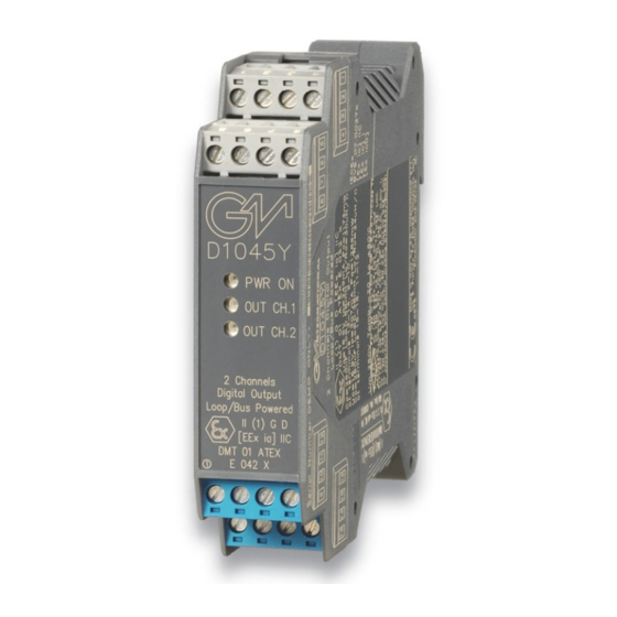
Ordering information Model: D1045Y Power Bus enclosure Front Panel and Features Output to Zone 0 (Zone 20), Division 1, installation in Zone 2, Division 2. Voltage input with isolated commands, loop powered or bus powered. Suitable for driving 1 or 2 positions directional solenoid valves. - Page 4 Parameters Table In the system safety analysis, always check the Hazardous Area/Hazardous Locations devices to conform with the related system documentation, if the device is Intrinsically Safe check its suitability for the Hazardous Area/Hazardous Locations and gas group encountered and that its maximum allowable voltage, current, power (Ui/Vmax, Ii/Imax, Pi/Pi) are not exceeded by the safety parameters (Uo/Voc, Io/Isc, Po/Po) of the D1045 Associated Apparatus connected to it.
-
Page 5: Function Diagram
NON HAZARDOUS LOCATIONS, CLASS I, DIVISION 2, CLASS II, DIVISION 1, GROUPS E, F, G, CLASS III, DIVISION 1, GROUPS A, B, C, D T-Code T4, CLASS I, ZONE 2, GROUP IIC T4 CLASS I, ZONE 0, GROUP IIC MODEL D1045Y Solenoid Supply 24 Vdc Valve... -
Page 6: Output Diagram
Loop Powered (Close Terminals) Common positive connection Solenoid Valve Out 2-B Output Diagram D1045Y OUTPUT DIAGRAM OUT A D1045Y OUTPUT DIAGRAM OUT B V (V) D1045Y Output Diagram A V (V) D1045Y Output Diagram B 17.0 V (no load) 17.0 V (no load) -
Page 7: Operation
Operation Each of the two independent and isolated channels of D1045Y accepts an input from Safe Area/Non Hazardous Locations (logic level or switch contact) and provides an output (see the output diagram on data sheet for details of voltage and current to the load) in Hazardous Area/Hazardous Locations to drive Intrinsically Safe loads (solenoid valves, audible alarms, signaling leds etc.). -
Page 8: Installation
Installation D1045 is a digital output isolator housed in a plastic enclosure suitable for installation on T35 DIN Rail according to EN50022. D1045 unit can be mounted with any orientation over the entire ambient temperature range, see section “Installation in Cabinet” and "Installation of Electronic Equipments in Cabinet" Instruction Manual D1000 series for detailed instructions.
Need help?
Do you have a question about the D1045Y and is the answer not in the manual?
Questions and answers