Table of Contents
Advertisement
Quick Links
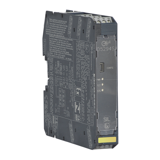
D5294S
INSTRUCTION & SAFETY MANUAL
5 A SIL 3 NO contact Relay Output Module
for NE or F&G/ND Load,
with full diagnostic and Modbus, DIN-Rail,
Power Bus and Termination Board, Model D5294S
D5294 - 5 A SIL 3 NO contact Relay Out Module for NE or F&G/ND Load with full diagnostic and Modbus
G.M. International ISM0123-14
Advertisement
Table of Contents

Subscribe to Our Youtube Channel
Related Manuals for GMI D5294S


Summary of Contents for GMI D5294S
- Page 1 NE or F&G/ND Load, with full diagnostic and Modbus, DIN-Rail, Power Bus and Termination Board, Model D5294S D5294 - 5 A SIL 3 NO contact Relay Out Module for NE or F&G/ND Load with full diagnostic and Modbus G.M. International ISM0123-14...
-
Page 2: Technical Data
Characteristics General Description: The The D5294S is a relay module suitable for the switching of safety related circuits, up to SIL 3 level according to IEC 61508:2010 Ed. 2 for high risk industries. It provides isolation between input and output contacts. A wide compatibility towards different DCS/PLC is guaranteed: driving line pulse testing, executed by DCS/PLC, is permitted by a dedicated internal circuit, to prevent relay and LED flickering. -
Page 3: Ordering Information
Ordering information Power Bus and DIN-Rail accessories: Model: D5294S Connector JDFT050 Cover and fix MCHP196 Terminal block male MOR017 Terminal block female MOR022 Operating parameters are programmable from PC by the GM Pocket Portable Adapter PPC5092 via USB serial line and SWC5090 Configurator software. -
Page 4: Function Diagram
Function Diagram SAFE AREA, ZONE 2 GROUP IIC T4, NON HAZARDOUS LOCATIONS, CLASS I, DIVISION 2, GROUPS A, B, C, D T-Code T4, CLASS I, ZONE 2, GROUP IIC T4 MODEL D5294S Load and Supply 24 Vdc Line 10 -... - Page 5 Safety Function and Failure behavior: D5294S is considered to be operating in Low Demand mode, as a Type A module, having Hardware Fault Tolerance (HFT) = 0. In the 1st Functional Safety application, the normal state operation of relay module is energized, with NE (Normally Energized) load.
- Page 6 Safety Function and Failure behavior: D5294S is considered to be operating in Low Demand mode, as a Type A module, having Hardware Fault Tolerance (HFT) = 0. In the 2nd Functional Safety application, the normal state operation of relay module is de-energized, with ND (Normally De-energized) load.
- Page 7 Testing procedure at T-proof The proof test shall be performed to reveal dangerous faults which are undetected by diagnostic. This means that it is necessary to specify how dangerous undetected faults, which have been noted during the FMEDA, can be revealed during proof test. Before of specific Proof test, execute the following general proof test: connect the load supply lines to terminal blocks “15”...
- Page 8 Description: In this application D5294S module monitors Load Power DC/AC line (Pins 15-16) and Out NE or F&G/ND Load (Pins 13-14) by internal diagnostic circuits and uses Fault Out 1 or Fault Out 2 NO contact to signal presence of faults on them. At pages 11-12 it’s shown how to configure and to monitor the diagnostic operation parameters (as fault conditions), by means of Modbus IN/OUT protocol with RS485 connection (Pins 5-6) or by PPC5092 adapter and SWC5090 related software.
- Page 9 Description: In this application D5294S module monitors Load Power DC/AC line (Pins 15-16) and Out NE or F&G/ND Load (Pins 13-14) by internal diagnostic circuits and uses Modbus protocol with RS485 connection to signal presence of faults on them. At pages 11-12 it’s shown how to configure and to monitor the diagnostic operation parameters (as fault conditions), by means of Modbus IN/OUT protocol with RS485 connection (Pins 5-6) or by PPC5092 adapter and SWC5090 related software.
-
Page 10: Operation
Operation The single channel 5 A Relay Output D5294S is a relay module suitable for the switching of safety related circuits, up to SIL 3 level according to IEC 61508:2010 Ed.2 for high risk industries. It provides isolation between input and output contacts. D5294S has 2+2 SPST relay contacts connected in parallel and then in series to avoid spurious trip and to increase availability (see function diagram). - Page 11 The Pocket Portable Adapter type PPC5092 is suitable to connect the module D5294S to a PC via USB serial line, in order to configure and to monitor the operation parameters by means of SWC5090 software. The PPC5092 unit is connected to D5294S by mini USB and to PC by USB port. This adapter is not ATEX, UL or FM approved and is only to be used in Safe Area/Non Hazardous Locations.
- Page 12 Supported ModBus Parameters Parameters Details: D5294S communicates via Modbus RTU-485 protocol. Below are all available registers. Address 17: Supported ModBus Baudrates Param. Index Baudrate Description Notes Type (12) Address 4800 G.M. Factory Code 9600 Instrument Code 19200 Identification Option Code...
Need help?
Do you have a question about the D5294S and is the answer not in the manual?
Questions and answers