
Related Manuals for GMI D5290S


Summary of Contents for GMI D5290S
- Page 1 D5290S INSTRUCTION & SAFETY MANUAL 10 A SIL 3 Relay Output Module for NE Load, DIN-Rail and Termination Board, Model D5290S D5290 - 10 A SIL 3 Relay Output Module for NE Load G.M. International ISM0111-8...
- Page 2 3) short circuit fault detection: when enabled, it allows DCS/PLC to detect short circuit fault of module. D5290S provides two NO contacts for normally energized load and a NC contact for service purpose, in order to switch the NE load on both supply lines.
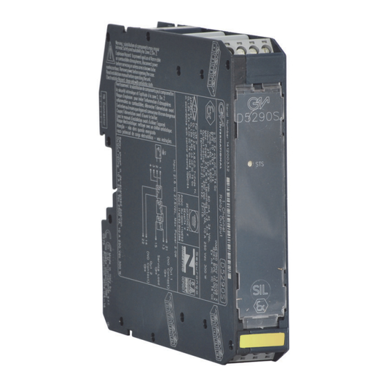
- Page 3 Ordering Information DIN-Rail accessories: Cover and fix MCHP196 Model: D5290S Front Panel and Features SIL 3 according to IEC 61508:2010 Ed. 2 for Tproof = 14 / 20 yrs (≤10% / >10 % of total SIF). PFDavg (1 year) 7.01 E-06, SFF 99.17 % for NE Load.
- Page 4 Function Diagram SAFE AREA, ZONE 2 GROUP IIC T4, NON HAZARDOUS LOCATIONS, CLASS I, DIVISION 2, GROUPS A, B, C, D T-Code T4, CLASS I, ZONE 2, GROUP IIC T4 MODEL D5290S (NO2) 21 Out 1 (NO contact) (CM1) 13...
- Page 5 Safety Function and Failure behavior: D5290S is considered to be operating in Low Demand mode, as a Type A module, having Hardware Fault Tolerance (HFT) = 0. In the 1st Functional Safety application, the normal state operation of relay module is energized, with NE (Normally Energized) load.
- Page 6 Safety Function and Failure behavior: D5290S is considered to be operating in Low Demand mode, as a Type A module, having Hardware Fault Tolerance (HFT) = 0. In the 2nd Functional Safety application, the normal state operation of relay module is energized, with NE (Normally Energized) loads.
- Page 7 D5290S relay module is suitable for the switching of safety related circuits, providing isolation between the input and output contacts. D5290S provides two NO contacts for normally energized load and a NC contact for service purpose, in order to switch the NE load on both supply lines.
- Page 8 Start-up Before powering the inputs of unit check that all wires are properly connected, also verifying their polarity. Check conductors for exposed wires that could touch each other causing dangerous unwanted shorts. Enabling input, the “RELAY STATUS” yellow led must be lit and load circuit must be energized because relay output contacts (Out 1 and Out 2) are closed. Indeed, disabling input, the “RELAY STATUS”...
Need help?
Do you have a question about the D5290S and is the answer not in the manual?
Questions and answers