baltur TBG 45 ME Instruction Manual For Installation, Use And Maintenance
Two-stage progressive / modulating burners with electronic cam "bt 3"
Hide thumbs
Also See for TBG 45 ME:
- User instruction manual (136 pages) ,
- Installation, use and maintenance instruction manual (72 pages) ,
- User instruction manual (80 pages)
Table of Contents
Advertisement
Available languages
Available languages
Quick Links
ITALIANO
Manuale istruzioni per l'installazione, l'uso e
la manutenzione
Instruction manual for
installation, use and maintenance
ISTRUZIONI ORIGINALI (IT)
ORIGINAL INSTRUCTIONS (IT)
BRUCIATORI A DUE STADI PROGRESSIVI / MODULANTI CON
TWO-STAGE PROGRESSIVE / MODULATING BURNERS WITH
IT
EN
CAMMA ELETTRONICA BT 3..
ELECTRONIC CAM "BT 3".
TBG 45 ME
17230020
TBG 60 ME
17300020
0006081532_202305
Advertisement
Chapters
Table of Contents

Related Manuals for baltur TBG 45 ME


Summary of Contents for baltur TBG 45 ME
- Page 1 BRUCIATORI A DUE STADI PROGRESSIVI / MODULANTI CON CAMMA ELETTRONICA BT 3.. TWO-STAGE PROGRESSIVE / MODULATING BURNERS WITH ELECTRONIC CAM "BT 3". ITALIANO TBG 45 ME Manuale istruzioni per l'installazione, l'uso e la manutenzione 17230020 Instruction manual for TBG 60 ME...
-
Page 3: Table Of Contents
ITALIANO ITALIANO SOMMARIO Avvertenze per l'uso in condizioni di sicurezza ..................................2 Caratteristiche tecniche ........................................6 Materiale a corredo ........................................7 Targa identificazione bruciatore ....................................7 Campo di lavoro ...........................................8 Caratteristiche tecnico funzionali ....................................9 Caratteristiche costruttive ......................................9 Descrizione componenti ......................................10 Quadro elettrico .........................................10 Dimensioni di ingombro ......................................11 Applicazione del bruciatore alla caldaia ...................................12 Rivestimento refrattario ......................................12 Predisposizione per attacco rampa verso l'alto................................13... -
Page 4: Avvertenze Per L'uso In Condizioni Di Sicurezza
Standard EN 746-2. comunque da inosservanza delle istruzioni date dal costruttore stesso. Contattare gli uffici commerciali Baltur. • Le macchine prodotte hanno una vita minima di 10 anni, se •... - Page 5 • L’eventuale riparazione dei prodotti dovrà essere effettuata sul manuale solamente da un centro di assistenza autorizzato da BALTUR o • L’impianto di alimentazione del combustibile sia dimensionato dal suo distributore locale, utilizzando esclusivamente ricambi per la portata necessaria al bruciatore e che sia dotato di tutti i originali.
- Page 6 ITALIANO AVVERTENZE PARTICOLARI PER L’USO DEL GAS. comporta l’osservanza di alcune regole fondamentali quali: - non toccare l’apparecchio con parti del corpo bagnate o umide • Verificare che la linea di adduzione e la rampa siano conformi alle e/o a piedi umidi; norme e prescrizioni vigenti.
- Page 7 ITALIANO A CURA DELL'INSTALLATORE • L’arresto d’emergenza dovrà essere operato garantendo i se- guenti requisiti: • Installare un idoneo sezionatore per ciascuna linea di alimenta- - Il dispositivo elettrico di arresto di emergenza deve soddisfare i zione del bruciatore. "requisiti speciali per interruttori di comando con apertura diret- •...
-
Page 8: Caratteristiche Tecniche
ITALIANO CARATTERISTICHE TECNICHE MODELLO TBG 45 ME TBG 60 ME Potenza termica massima metano Potenza termica minima metano mg/kWh ¹) emissioni metano Classe 3 Classe 3 Funzionamento Bistadio progressivo / modulante Bistadio progressivo / modulante Trasformatore metano 50 Hz 26 kV - 40 mA - 230 V 26 kV - 40 mA - 230V Stm³/h... -
Page 9: Materiale A Corredo
ITALIANO MATERIALE A CORREDO MODELLO TBG 45 ME TBG 60 ME Guarnizione flangia attacco bruciatore Cordone isolante N° 4 M 12 N° 4 M 12 Prigionieri N° 4 M 12 N° 4 M 12 Dadi esagonali N° 4 Ø 12 N°... -
Page 10: Campo Di Lavoro
ITALIANO CAMPO DI LAVORO TBG 60P TBG 45P TBG 60PN TBG 45PN TBG 60P-V TBG 45P-V TBG 60ME TBG 45ME mbar m /h(Metano) m /h(G.P.L.) IMPORTANTE I campi di lavoro sono ottenuti su caldaie di prova rispondenti alla norma EN676 e sono orientativi per gli accoppiamenti bruciatore-caldaia. Per il corretto funzionamento del bruciatore le dimensioni della camera di combustione devono essere rispondenti alla normativa vigente;... -
Page 11: Caratteristiche Tecnico Funzionali
ITALIANO CARATTERISTICHE TECNICO FUNZIONALI CARATTERISTICHE COSTRUTTIVE • Bruciatore di gas conforme alle normative europee EN 676 ed I bruciatori risultano composti da: alle Direttive Europee 2006/42/CE; 2014/30/UE; 2014/35/UE; • Presa d'aria comburente con serranda a farfalla per la regolazio- (UE) 2016/426. ne della portata d'aria. -
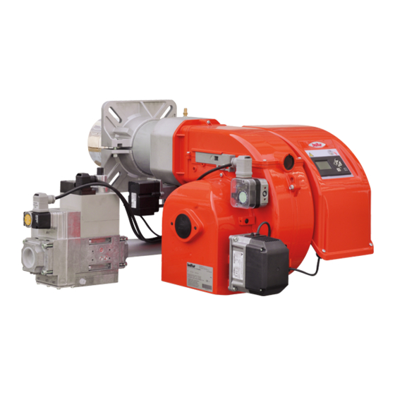
Page 12: Descrizione Componenti
ITALIANO DESCRIZIONE COMPONENTI Testa di combustione Guarnizione Flangia attacco bruciatore Dispositivo regolazione testata Coperchio chiocciola Flangia attacco rampa gas Quadro elettrico Motore Servomotore regolazione aria Servomotore regolazione gas Pressostato aria Targa identificazione bruciatore QUADRO ELETTRICO Apparecchiatura Trasformatore d'accensione Contattore motore Relè... -
Page 13: Dimensioni Di Ingombro
ITALIANO DIMENSIONI DI INGOMBRO Modello E Ø F Ø TBG 45 ME 140 ÷ 300 TBG 60 ME 140 ÷ 300 Modello LØ N Ø TBG 45 ME Rp 1"1/2 200 ÷ 245 TBG 60 ME Rp 1"1/2 225 ÷ 300... -
Page 14: Applicazione Del Bruciatore Alla Caldaia
ITALIANO APPLICAZIONE DEL BRUCIATORE ALLA CALDAIA RIVESTIMENTO REFRATTARIO Il rivestimento refrattario posto sul portellone della camera di combu- stione, protegge il portellone della caldaia dalle elevate temperature che si sviluppano nella camera di combustione. Permette inoltre di migliorare il raggiungimento della temperature otti- mizzando la combustione. -
Page 15: Predisposizione Per Attacco Rampa Verso L'alto
ITALIANO PREDISPOSIZIONE PER ATTACCO RAMPA VERSO L'ALTO Se si desidera portare il lato di ingresso rampa verso l'alto, prima di applicare il bruciatore alla caldaia, seguire la procedura seguente: • Seguendo le istruzioni riportate al paragrafo " Manutenzione", estrarre il gruppo miscelazione e togliere la vite (8) che collega l'asta di avanzamento (14) del gruppo con il tubo mandata gas (15).Togliere la vite (16) che collega il miscelatore gas (17) al tubo. -
Page 16: Linea Di Alimentazione
ITALIANO LINEA DI ALIMENTAZIONE Lo schema di principio della linea di alimentazione gas è riportato nella figura sotto. La rampa gas è omologata secondo normativa EN 676 e viene fornita separatamente dal bruciatore. PERICOLO / ATTENZIONE Occorre installare, a monte della valvola gas, una valvola di intercettazione manuale e un giunto antivibrante, disposti secondo quanto indicato nello schema di principio. -
Page 17: Collegamenti Elettrici
ITALIANO COLLEGAMENTI ELETTRICI • Tutti i collegamenti devono essere eseguiti con filo elettrico flessibile. • Rispettare le normative nazionali ed europee applicabili relative alla sicurezza elettrica; • Le sezioni dei conduttori non specificati sono da considerarsi di 0,75 mm². • Le linee elettriche devono essere distanziate dalle parti calde. - Page 18 ITALIANO • Avvitare le viti (6) esercitando una coppia di serraggio adeguata ad assicurare la corretta tenuta, per richiudere il coperchio del quadro eletttrico. CAUTELA / AVVERTENZE L’apertura del quadro elettrico del bruciatore è consentita esclusivamente a personale professionalmente qualificato. Il motore elettrico è...
-
Page 19: Descrizione Del Funzionamento A Due Stadi Progressivi
ITALIANO DESCRIZIONE DEL FUNZIONAMENTO A DUE bruciatore viene arrestato. Riabbassandosi, la temperatura o pressione al di sotto del valore di STADI PROGRESSIVI intervento del dispositivo di controllo, il bruciatore viene nuovamente avviato secondo il programma precedentemente descritto. I bruciatori ad aria soffiata con modulazione elettronica sono adatti per Nel normale funzionamento la sonda di modulazione applicata alla funzionare su focolari in forte pressione o in depressione secondo le caldaia rileva le variazioni di temperatura o pressione, ed automati-... -
Page 20: Accensione E Regolazione
ITALIANO ACCENSIONE E REGOLAZIONE regolazione del pressostato ad un valore sufficiente per rilevare una pressione di aria esistente durante la fase di preventilazione. • Effettuare lo spurgo dell’aria contenuta nella tubazione del gas I pressostati di controllo della pressione del gas (minima e massima) con le cautele del caso e con porte e finestre aperte. -
Page 21: Corrente Ionizzazione
ITALIANO SENSORE FIAMMA • Verificare il funzionamento del rilevatore di fiamma come segue: - staccare il cavo proveniente dall'elettrodo di ionizzazione; - avviare il bruciatore; - l'apparecchiaura completerà il ciclo di controllo e dopo due secondi manderà in blocco il bruciatore per mancata fiamma di accensione; - spegnere il bruciatore;... -
Page 22: Descrizione Del Funzionamento Pressostato Aria
ITALIANO DESCRIZIONE DEL FUNZIONAMENTO PRESSOSTATO ARIA Il pressostato aria ha lo scopo di mettere in sicurezza (blocco) l’appa- recchiatura se la pressione dell’aria non è quella prevista. Il pressostato deve quindi essere regolato per intervenire chiudendo il contatto NO (normalmente aperto) quando la pressione dell’aria nel bruciatore raggiunge il valore a cui è... -
Page 23: Regolazione Aria Sulla Testa Di Combustione
è eccessiva, si potrebbe verificare forte turbolenza d'aria e quindi difficoltà d'accensione. Valore indicato dall'indice Modello 3 - 31 0 - 3,2 TBG 45 ME 6-34 0 - 3,2 TBG 60 ME Distanza testa-disco; regolare la distanza X seguendo le in- dicazioni: •... -
Page 24: Schema Di Regolazione Distanza Disco Elettrodi
TBG 45P-ME MIN 8 TBG 60P-ME 1 - Elettrodo ionizzazione 2 - Elettrodo accensione TBG 45 ME 3 - Disco fiamma TBG 60 ME 4 - Miscelatore 5 - Tubo mandata gas E - ATTENZIONE: uscita foro ugello centrale in prossimità della punta dell'elettrodo. -
Page 25: Manutenzione
ITALIANO MANUTENZIONE Effettuare almeno una volta all’anno e comunque in conformità alle norme vigenti, l’analisi dei gas di scarico della combustione verificando la correttezza dei valori di emissioni. • Controllare che il filtro del combustibile sia pulito. Se necessario sostituirlo. •... -
Page 26: Tempi Di Manutenzione
ITALIANO TEMPI DI MANUTENZIONE Descrizione particolare Azione da eseguire TESTA DI COMBUSTIONE CONTROLLO VISIVO, INTEGRITA' CERAMICHE, SMERIGLIATURA ESTREMITA', VERIFICARE ANNO ELETTRODI DISTANZA, VERIFICARE CONNESSIONE ELETTRICA CONTROLLO VISIVO INTEGRITA' EVENTUALI DEFORMAZIONI, PULIZIA ANNO DISCO FIAMMA CONTROLLO VISIVO, INTEGRITA' CERAMICHE, SMERIGLIATURA ESTREMITA', VERIFICARE ANNO SONDA DI IONIZZAZIONE DISTANZA, VERIFICARE CONNESSIONE ELETTRICA... -
Page 27: Vita Attesa
ITALIANO VITA ATTESA La vita attesa dei bruciatori e dei relativi componenti dipende molto dal tipo di applicazione su cui il bruciatore è installato, dai cicli, dalla potenza erogata, dalle condizioni dell’ambiente in cui si trova, dalla frequenza e modalità di manutenzione, ecc. ecc. Le normative relative ai componenti di sicurezza prevedono una vita attesa di progetto espressa in cicli e/o anni di funzionamento. -
Page 28: Precisazioni Sull'uso Del Propano
ITALIANO PRECISAZIONI SULL'USO DEL PROPANO • Valutazione, indicativa, del costo di esercizio; - 1 m3 di gas liquido in fase gassosa ha un potere calorifico inferiore, di circa 25,6 kWh - Per ottenere 1 m3 di gas occorrono circa 2 Kg di gas liquido che corrispondono a circa 4 litri di gas liquido. -
Page 29: Schema Di Principio Per Riduzione Pressione G.p.l. A Due Stadi Per Bruciatore Oppure Caldaia
ITALIANO SCHEMA DI PRINCIPIO PER RIDUZIONE PRESSIONE G.P.L. A DUE STADI PER BRUCIATORE OPPURE CALDAIA Manometro e presa di pressione Riduttore di 1° salto Riduttore di 2° salto Uscita ~ 1,5 bar Uscita ~ Pressione minima alimentazione rampa Portata ~ il doppio del massimo richiesto dall’utilizzatore Portata ~ il doppio del massimo richiesto dall’utilizzatore Giunto antivibrante Filtro... -
Page 30: Istruzioni Montaggio Riduzioni Per Gpl
TBG 45 ME combustibile GPL. TBG 60 ME 1) Dopo aver allentato le viti di fissaggio 1 rimuovere le riduzioni A (N.2) dalle rispettive sedi. -
Page 31: Istruzioni Per L'accertamento Delle Cause Di Irregolarità Nel Funzionamento E La Loro Eliminazione
ITALIANO ISTRUZIONI PER L'ACCERTAMENTO DELLE CAUSE DI IRREGOLARITÀ NEL FUNZIONAMEN- TO E LA LORO ELIMINAZIONE IRREGOLARITÁ POSSIBILE CAUSA RIMEDIO L'apparecchio va in "blocco" con Disturbo della corrente di ionizzazione Invertire l'alimentazione (lato 230V) del fiamma (lampada rossa accesa). da parte del trasformatore di accensio- trasformatore di accensione e verificare con Guasto circoscritto al dispositivo di micro-amperometro analogico. -
Page 32: Schemi Elettrici
ITALIANO SCHEMI ELETTRICI 30 / 34 0006081532_202305... - Page 33 ITALIANO 31 / 34 0006081532_202305...
- Page 34 ITALIANO 32 / 34 0006081532_202305...
- Page 35 ITALIANO APPARECCHIATURA GNYE VERDE / GIALLO SENSORE FIAMMA SONDA DI PRESSIONE BRUNO SONDA DI TEMPERATURA NERO RELE’ TERMICO CONNETTORE NERO CON SOVRASTAMPA FU1÷4 FUSIBILI SPIA BLOCCO ESTERNA / LAMPADA FUNZIONAMENTO RESISTENZE AUSILIARIE CONTATTORE MOTORE VENTOLA CONTATTORE ESTERNO MOTORE VENTOLA "REGOLATORE ELETTRONICO “PRESSOSTATO DI MASSIMA“...
- Page 36 ITALIANO 34 / 34 0006081532_202305...
- Page 37 ENGLISH ENGLISH SUMMARY Warnings for use in safety conditions ....................................2 Technical specifications ........................................6 Standard accessories ........................................7 Burner identification plate ......................................7 Operating range ...........................................8 Technical functional characteristics ....................................9 Design characteristics ........................................9 Component description ......................................10 Electrical panel ...........................................10 Overall dimensions ........................................11 Burner connection to the boiler ......................................12 Refractory lining .........................................12 Preparation for connecting the train turned upward ..............................13 Supply line ..........................................14...
-
Page 38: Warnings For Use In Safety Conditions
• The burner must NOT be used in production cycles and industrial processes, the latter governed by the Standard EN 746-2 Con- tact sales offices Baltur. • The burner must be used in boilers for civil applications such as building heating and domestic hot water production. - Page 39 Contact only qualified personnel. - Set the burner fuel capacity to the power required by the heat • Any product repairs must only be carried out by BALTUR au- generator. thorised assistance centres or by its local distributor using only - Check combustion and adjust combustion air and fuel flow and ( original spare parts.
- Page 40 ENGLISH SPECIAL PRECAUTIONS WHEN USING GAS. - do not leave the equipment exposed to atmospheric agents (such as rain or sun etc.) unless there is explicit provision for • Check that the feed line and the train comply with current law and this;...
- Page 41 ENGLISH TO BE CARRIED OUT BY THE INSTALLER require a manual operation to be restored. - When the emergency device is restored, the burner must not • Install a suitable disconnecting switch for each burner supply line. be able to start autonomously, but a further “run” action by the •...
-
Page 42: Technical Specifications
ENGLISH TECHNICAL SPECIFICATIONS MODEL TBG 45 ME TBG 60 ME Maximum natural gas heat power Minimum natural gas heat power mg/kWh ¹) natural gas emissions Class 3 Class 3 Two-stage progressive / modulating Two-stage progressive / modulating Operation burner burner... -
Page 43: Standard Accessories
ENGLISH STANDARD ACCESSORIES MODEL TBG 45 ME TBG 60 ME Burner coupling flange gasket Insulating cord No. 4 M 12 No. 4 M 12 Stud bolts No. 4 M 12 No. 4 M 12 Hexagon nuts No. 4 Ø 12 No. -
Page 44: Operating Range
ENGLISH OPERATING RANGE TBG 60P TBG 45P TBG 60PN TBG 45PN TBG 60P-V TBG 45P-V TBG 60ME TBG 45ME mbar m /h(Metano) m /h(G.P.L.) IMPORTANT The operating ranges are obtained from test boilers corresponding to Standard EN676 and are indicative of the burner-boiler combination. For correct working of the burner, the size of the combustion chamber must correspond to current regulations;... -
Page 45: Technical Functional Characteristics
ENGLISH TECHNICAL FUNCTIONAL CHARACTERISTICS DESIGN CHARACTERISTICS • Gas burner compliant with the European standards EN 676 and Burners are composed by: with the European Directives 2006/42/CE; 2014/30/UE; 2014/35/ • Combustion air intake with throttle gate for the regulation of the UE;... -
Page 46: Component Description
ENGLISH COMPONENT DESCRIPTION Combustion head Seal Burner connection flange Combustion head adjustment device Scroll cover Gas train connector flange Electrical panel Motor Air regulation servomotor Gas regulation servomotor Air pressure switch Burner identification plate ELECTRICAL PANEL Control box Ignition transformer Motor contactor Thermal relay (only with three-phase power supply) START/STOP switch... -
Page 47: Overall Dimensions
ENGLISH OVERALL DIMENSIONS Model E Ø F Ø TBG 45 ME 140 ÷ 300 TBG 60 ME 140 ÷ 300 Model LØ N Ø TBG 45 ME Rp 1"1/2 200 ÷ 245 TBG 60 ME Rp 1"1/2 225 ÷ 300... -
Page 48: Burner Connection To The Boiler
ENGLISH BURNER CONNECTION TO THE BOILER REFRACTORY LINING The refractory lining on the hatch of the combustion chamber protects the boiler hatch from the high temperatures that develop in the com- bustion chamber. It also abbreviates the time necessary to reach the proper temperature, optimizing combustion. -
Page 49: Preparation For Connecting The Train Turned Upward
ENGLISH PREPARATION FOR CONNECTING THE TRAIN TURNED UPWARD If you wish to orient the entrance train side upward before applying the burner to the boiler, proceed as follows. • Following the instructions detailed in the “Maintenance” para- graph, extract the mixer assembly and remove the screw (8) which connects the unit’s forward movement rod (14) to the gas delivery pipe (15).Remove the screw (16) which connects the gas mixer (17) to the pipe. -
Page 50: Supply Line
ENGLISH SUPPLY LINE The figure below shows the gas supply line block diagram. The gas train is certified in compliance with EN 676 Standard and supplied separately from the burner. DANGER / ATTENTION Install a manual shut-off valve and a vibration-proof joint upstream of the gas valve, according to the layout shown in the block diagram. -
Page 51: Electrical Connections
ENGLISH ELECTRICAL CONNECTIONS • It is advisable to make all connections with flexible electric wire. • Observe applicable National and European Standards regarding electrical safety; • Conductor cross-sections not specified are to be considered as 0,75 mm². • The power lines must be distanced from the hot parts. •... - Page 52 ENGLISH • To close the electrical panel lid, tighten the screws (6) with ade- quate torque to ensure the correct seal. CAUTION / WARNINGS Only professionally qualified personnel may open the burner electrical switchboard. The electric motor is equipped with an automatic reset thermal cut-out that causes it to stop when overheating.
-
Page 53: Description Of The Two-Stage Progressive Operation
ENGLISH DESCRIPTION OF THE TWO-STAGE PRO- vomotors. In this way the burner is able to optimise the request of heat to be GRESSIVE OPERATION supplied to the boiler. If a flame does not appear within three seconds from the opening of Blown air burners with electronic modulation may be used on hearths the gas valves, the control equipment will "lockout"... -
Page 54: Starting Up And Regulation
ENGLISH STARTING UP AND REGULATION expected range. The minimum value pressure switch makes use of the NO (normally • Bleed out the air contained in the gas piping, with due precautions open) contact which is closed when the pressure switch detects a pres- and with doors and windows open. -
Page 55: Ionisation Current
ENGLISH FLAME SENSOR • Verify the flame detector operation as follows: - disconnect the wire coming from the ionisation electrode; - start the burner; - The equipment will complete the control cycle and after two seconds will lock the burner due to the lack of ignition flame; - switch off the burner;... -
Page 56: Air Pressure Switch Functional Description
ENGLISH AIR PRESSURE SWITCH FUNCTIONAL DESCRIPTION The air pressure switch stops the equipment operation if air pressure is not at the expected value. The pressure switch must therefore be adjusted so that it is triggered to close the NO (normally open) contact when the air pressure in the burner reaches the set value. -
Page 57: Air Regulation On The Combustion Head
Model Value indicated by index 4 3 - 31 0 - 3,2 TBG 45 ME 6-34 0 - 3,2 TBG 60 ME Head-disk distance; adjust distance X following the in- structions: •... -
Page 58: Diagram For Regulating The Electrode Disk Distance
TBG 45P-ME MIN 8 TBG 60P-ME 1 - Ionisation electrode 2 - Ignition electrode TBG 45 ME 3 - Flame disc TBG 60 ME 4 - Mixer 5 - Gas delivery pipe E - WARNING: nozzle hole outlet near the electrode tip. -
Page 59: Maintenance
ENGLISH MAINTENANCE Analyse combustion gases and check that the emission values are correct at least once a year, in compliance with current law. • Check that the fuel filter is clean. Replace it, if necessary. • Check that all components of the combustion head are in good condition, have not been deformed and are free from impurities or deposits deriving from the installation environment and/or from combustion. -
Page 60: Maintenance Time
ENGLISH MAINTENANCE TIME Part description Action to be performed COMBUSTION HEAD VISUAL INSPECTION OF THE INTEGRITY OF CERAMICS. TIP GRINDING, CHECK DISTANCE, CHECK YEAR ELECTRODES ELECTRICAL CONNECTION INTEGRITY VISUAL CHECK FOR ANY DEFORMATIONS, CLEANING, YEAR FLAME DISC VISUAL INSPECTION OF THE INTEGRITY OF CERAMICS. TIP GRINDING, CHECK DISTANCE, CHECK YEAR IONISATION PROBE ELECTRICAL CONNECTION... -
Page 61: Expected Lifespan
ENGLISH EXPECTED LIFESPAN The expected lifespan of burners and relevant components depends very much from the type of application on which the burner is installed, from cycles ,of delivered power, from the conditions of the environment in which it is located, from maintenance frequency and mode, etc. Standards about safety components provide for a project expected lifespan expressed in cycles and/or years of operation. -
Page 62: Specifications For Propane Use
ENGLISH SPECIFICATIONS FOR PROPANE USE • Operating costs approximate assessment; - 1 m3 of liquid gas in gaseous stage has a lower heating capaci- ty, of nearly 25.6 kWh. - To obtain 1 cu.m of gas, about 2 kg of liquid gas are needed, i.e. about 4 litres of liquid gas. -
Page 63: Block Diagram Illustrating The Principle Of L.p.g. Pressure Reduction In Two Stages For Burner Or Boiler
ENGLISH BLOCK DIAGRAM ILLUSTRATING THE PRINCIPLE OF L.P.G. PRESSURE REDUCTION IN TWO STAGES FOR BURNER OR BOILER Pressure gauge and pressure intake 1st step reducer 2nd step reducer Output ~ 1.5 bar Output, about the minimum gas train supply pressure Flow rate ~ double the maximum required by the user Flow rate ~ double the maximum required by the user Vibration-proof joint... -
Page 64: Reducers Assembly Instructions For Lpg
LPG TBG 45 ME fuel. TBG 60 ME 1) After loosening the fastening screws 1 remove the two reducers A (N.2) from their respective seats. -
Page 65: Instructions For Determining The Cause Leading To Irregularities In The Operation And Their Elimination
ENGLISH INSTRUCTIONS FOR DETERMINING THE CAUSE LEADING TO IRREGULARITIES IN THE OPE- RATION AND THEIR ELIMINATION IRREGULARITY POSSIBLE CAUSE REMEDY Appliance locks out due to no flame Disturbance to ionization current from Invert the ignition transformer power supply (red light lit).The fault is in the flame the ignition transformer. -
Page 66: Wiring Diagrams
ENGLISH WIRING DIAGRAMS 30 / 34 0006081532_202305... - Page 67 ENGLISH 31 / 34 0006081532_202305...
- Page 68 ENGLISH 32 / 34 0006081532_202305...
- Page 69 ENGLISH CONTROL BOX GNYE GREEN / YELLOW Flame sensor BLUE PRESSURE PROBE BROWN TEMPERATURE PROBE BLACK THERMAL RELAY BLACK CONNECTOR WITH OVERPRINT FU1÷4 FUSES EXTERNAL LOCK INDICATOR LIGHT/ AUXILIARY HEATING ELEMENT OPERATION LAMP FAN MOTOR CONTACTOR EXTERNAL CONTACTOR FAN MOTOR ”ELECTRONIC REGULATOR “MAXIMUM PRESSURE SWITCH“...
- Page 70 ENGLISH 34 / 34 0006081532_202305...
- Page 72 BALTUR S.P.A. Via Ferrarese, 10 44042 Cento (Fe) - Italy Tel. +39 051-6843711 Fax. +39 051-6857527/28 www.baltur.it info@baltur.it Il presente catalogo riveste carattere puramente indicativo. La casa, pertanto, si riserva ogni possibilità di modifica dei dati tecnici e di quant'altro in esso riportato.
Need help?
Do you have a question about the TBG 45 ME and is the answer not in the manual?
Questions and answers