Table of Contents
Advertisement
Available languages
Available languages
Quick Links
BRUCIATORI DI GAS A DUE STADI PROGRESSIVI / MODULANTI
CON CAMMA MECCANICA
PROGRESSIVE/MODULATING TWO-STAGE GAS BURNERS
WITH MECHANICAL CAM.
ITALIANO
TBG 480 MC
Manuale istruzioni per l'installazione,
IT
l'uso e la manutenzione
Installation, use and maintenance
EN
instruction manual
ISTRUZIONI ORIGINALI (IT)
ORIGINAL INSTRUCTIONS (IT)
0006160059_201511
Advertisement
Table of Contents

Subscribe to Our Youtube Channel
Related Manuals for baltur TBG 480 MC


Summary of Contents for baltur TBG 480 MC
- Page 1 BRUCIATORI DI GAS A DUE STADI PROGRESSIVI / MODULANTI CON CAMMA MECCANICA PROGRESSIVE/MODULATING TWO-STAGE GAS BURNERS WITH MECHANICAL CAM. ITALIANO TBG 480 MC Manuale istruzioni per l'installazione, l'uso e la manutenzione Installation, use and maintenance instruction manual ISTRUZIONI ORIGINALI (IT)
-
Page 3: Table Of Contents
ITALIANO ITALIANO SOMMARIO Avvertenze per l'uso in condizioni di sicurezza ..........................pag 3 Caratteristiche tecniche ..................................pag 6 Materiale a corredo ..................................pag 7 Targa identificazione bruciatore..............................pag 7 Dati registrazione prima accensione ............................pag 7 Campo di lavoro ..................................pag 8 Dimensioni di ingombro ................................pag 9 Descrizione componenti ................................pag 10 Descrizione componenti ................................pag 10 Caratteristiche costruttive .................................pag 12... - Page 4 ITALIANO DICHIARAZIONE DI CONFORMITÀ CE0085: DVGW CERT GmbH, Josef-Wirmer Strasse 1-3-53123 Bonn (D) Dichiariamo che i nostri bruciatori ad aria soffiata di combustibili luquidi, gassosi e misti, domestici e industriali, serie: BPM...; BGN…; BT…; BTG…; BTL…; TBML...; Comist…; GI…; GI…Mist; Minicomist…; PYR…; RiNOx…; Spark...; Sparkgas...; TBG...;TBL...;...
-
Page 5: Avvertenze Per L'uso In Condizioni Di Sicurezza
ITALIANO AVVERTENZE PER L'USO IN CONDIZIONI (bambini compresi) le cui capacità fisiche, sensoriali o mentali siano ridotte, oppure con mancanza di esperienza o di cono- DI SICUREZZA scenza. • l'uso dell'apparecchio è consentito a tali persone solo nel caso SCOPO DEL MANUALE in cui possano beneficiare, attraverso l'intermediazione di una Il manuale si propone di contribuire all'utilizzo sicuro del prodotto persona responsabile, di informazioni relative alla loro sicurez-... - Page 6 • Prima di avviare il bruciatore e almeno una volta all’anno, far ef- • L’eventuale riparazione dei prodotti dovrà essere effettuata so- fettuare da personale professionalmente qualificato le seguenti lamente da un centro di assistenza autorizzato da BALTUR o operazioni: dal suo distributore locale, utilizzando esclusivamente ricambi - Tarare la portata di combustibile del bruciatore secondo la originali.
- Page 7 ITALIANO Avvertenze particolari per l’uso del gas. che il filo possa venire a contatto con parti metalliche. • Verificare che la linea di adduzione e la rampa siano conformi • L’alimentazione elettrica del bruciatore deve prevedere il neutro alle norme e prescrizioni vigenti. a terra.
-
Page 8: Caratteristiche Tecniche
ITALIANO CARATTERISTICHE TECNICHE MODELLO TBG 480 MC POTENZA TERMICA MASSIMA METANO 4800 POTENZA TERMICA MINIMA METANO mg/kWh ¹) EMISSIONI METANO Classe III (<80 mg/kWh) FUNZIONAMENTO Modulazione elettronica TRASFORMATORE METANO 50 Hz 8kV - 20 mA - 230V TRASFORMATORE METANO 60 Hz 8kV - 20 mA - 230V Stm³/h... -
Page 9: Materiale A Corredo
ITALIANO MATERIALE A CORREDO MODELLO TBG 480 MC FLANGIA ATTACCO BRUCIATORE GUARNIZIONE ISOLANTE PRIGIONIERI N°6 M20 DADI ESAGONALI N°6 M20 RONDELLE PIANE N°6 Ø20 TARGA IDENTIFICAZIONE BRUCIATORE 1 Logo aziendale 2 Ragione sociale azienda 3 Codice prodotto 4 Modello bruciatore... -
Page 10: Campo Di Lavoro
ITALIANO CAMPO DI LAVORO TBG 480MC IMPORTANTE I campi di lavoro sono ottenuti su caldaie di prova rispondenti alla norma EN676 e sono orientativi per gli accoppiamenti bruciato- re-caldaia. Per il corretto funzionamento del bruciatore le dimensioni della camera di combustione devono essere rispondenti alla normativa vigente;... -
Page 11: Dimensioni Di Ingombro
ITALIANO DIMENSIONI DI INGOMBRO Modello TBG 480 MC 1.940 Modello E Ø F Ø LØ TBG 480 MC Modello N Ø TBG 480 MC 9 / 32 0006160059_201511... -
Page 12: Descrizione Componenti
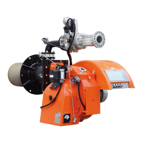
ITALIANO DESCRIZIONE COMPONENTI 1 Testa di combustione 2 Guarnizione 3 Flangia attacco bruciatore 4 Valvola farfalla gas 5 Servomotore regolazione modulazione 6 Display apparecchiatura 7 Gruppo serrande aria 8 Servomotore regolazione aria 9 Quadro elettrico 10 Cerniera 11 Motore ventola 12 Convogliatore aria in aspirazione 13 Presa di pressione gas alla testa di combustione 14 Modulatore regolazione aria - combustibile... -
Page 13: Caratteristiche Costruttive
ITALIANO CARATTERISTICHE COSTRUTTIVE CARATTERISTICHE TECNICO FUNZIONALI Il bruciatore risulta composto da: • Bruciatore di gas conforme alle normative europee EN 676 • Parte ventilante in lega leggera d'alluminio. ed alle Direttive Europee 2006/42/CE; 2006/95/CE; 97/23/CE; • Ventilatore centrifugo per alte prestazioni. 2004/108/CE. -
Page 14: Applicazione Del Bruciatore Alla Caldaia
ITALIANO APPLICAZIONE DEL BRUCIATORE ALLA CALDAIA MONTAGGIO GRUPPO TESTATA La testa del bruciatore viene imballata separatamente dal corpo bruciatore. Fissare il bruciatore al portellone caldaia nel seguente modo: • Posizionare sul cannotto la guarnizione isolante (13) • Fissare il gruppo testa (14) alla caldaia (1) tramite i prigionieri, le rondelle e i relativi dadi in dotazione (7). -
Page 15: Schema Di Principio Bruciatori A Gas
ITALIANO MONTAGGIO RAMPA GAS La rampa gas è omologata secondo normativa EN 676 e viene fornita separatamente. Sono possibili diverse soluzioni di montaggio (1), (2), (3) , della rampa gas. Scegliere la posizione più idonea in base alla conformazione del locale caldaia e alla posizione di ingresso della tubazione gas. -
Page 16: Collegamenti Elettrici
ITALIANO COLLEGAMENTI ELETTRICI • Tutti i collegamenti devono essere eseguiti con filo elettrico flessibile. • La sezione minima dei conduttori deve essere di 1.5 mm². • Le linee elettriche devono essere distanziate dalle parti calde. • L’installazione del bruciatore è consentita solo in ambienti con grado di inquinamento 2 come indicato nell’allegato M della nor- ma EN 60335-1:2008-07. -
Page 17: Linea Di Alimentazione
ITALIANO LINEA DI ALIMENTAZIONE SCHEMA DI PRINCIPIO PER L'INSTALLAZIONE SARACI- NESCA-FILTRO-STABILIZZATORE GIUNTO ANTIVIBRAN- Lo schema di principio della linea di alimentazione gas è riportato TE-RACCORDO APRIBILE. nella figura sotto. La rampa gas è omologata secondo normativa EN 676 e viene fornita separatamente dal bruciatore. -
Page 18: Descrizione Del Funzionamento
ITALIANO DESCRIZIONE DEL FUNZIONAMENTO La rampa gas in dotazione è composta da una valvola di sicu- rezza in versione ON/OFF e da una valvola principale a singolo stadio ad apertura lenta. La regolazione della portata di combustibile in primo e in secondo stadio è... -
Page 19: Descrizione Del Funzionamento Amodulazione
ITALIANO DESCRIZIONE DEL FUNZIONAMENTO A MODULAZIONE Quando il bruciatore è acceso alla portata minima, se la sonda di modulazione lo consente (regolata ad un valore di temperatura o pressione superiore a quella esistente in caldaia) il servomotore di regolazione aria / gas inizia a girare; •... -
Page 20: Accensione E Regolazione
ITALIANO ACCENSIONE E REGOLAZIONE • Può capitare che la corrente di ionizzazione sia contrastata dal- la corrente di scarica del trasformatore di accensione, le due E’ possibile effettuare il controllo della combustione su tutto il correnti hanno un percorso in comune sulla “massa” del bru- campo di lavoro del bruciatore comandando manualmente l’ap- ciatore, pertanto il bruciatore si porta in blocco per insufficiente parecchiatura. - Page 21 ITALIANO • Il pressostato aria ha lo scopo di impedire l’apertura delle val- vole gas se la pressione dell’aria non è quella prevista. Il pres- sostato deve quindi essere regolato per intervenire chiudendo il contatto quando la pressione dell’aria nel bruciatore raggiunge il valore sufficiente.
-
Page 22: Regolazione Aria Sulla Testa Di Combustione
ITALIANO REGOLAZIONE ARIA SULLA TESTA DI COMBUSTIONE CORRENTE IONIZZAZIONE Raggiunta l’erogazione masssima desiderata si provvede a Il valore minimo della corrente di ionizzazione necessario a far correggere la posizione del dispositivo che chiude l'aria sulla testa funzionare l'apparecchiatura, è riportato nello schema elettrico. di combustione, spostandolo in avanti o indietro, in modo di avere Il bruciatore dà... -
Page 23: Apparecchiatura Di Comando E Controllo Per Bruciatori A Gas Lme73
ITALIANO APPARECCHIATURA DI COMANDO E CONTROLLO PER BRUCIATORI A GAS LME73... per ulteriori informazioni consultare la Guida rapida dell'apparecchiatura fornita a corredo con il manuale. Il pulsanate reset di blocco ') (pulsante info) (EK) è l'elemento operativo chiave per resettare il controllo del bruciatore Info e per attivare / disattivare le funzioni diagnostiche. -
Page 24: Particolare Motore Sqm 40 Di Comando Modulazione Per Regolazione Cammes
ITALIANO PARTICOLARE MOTORE SQM 40 DI COMANDO MODULAZIONE PER REGOLAZIONE CAMMES Apertura massima aria (130°) Chiusura totale aria (bruciatore fermo) (0°) III Apertura minima aria (minore di camma IV) (10°) IV Apertura aria d'accensione (maggiore di camma III) (30°) B = Leva di inserzione ed esclusione accoppiamento motore - albero camme - Posizione 1= escluso - Posizione 2= inserito Per modificare la regolazione delle camme utilizzate, si agisce sui rispettivi anelli (I - II - III...) -
Page 25: Manutenzione
ITALIANO MANUTENZIONE • Pulire le serrande aria, il pressostato aria con presa di pressio- ne ed il relativo tubo se presenti. • Verificare lo stato degli elettrodi. Se necessario sostituirli. • Far pulire la caldaia ed il camino da personale specializzato in fumisteria, una caldaia pulita ha maggior rendimento, durata e silenziosità. -
Page 26: Tempi Di Manutenzione
ITALIANO TEMPI DI MANUTENZIONE TESTA DI COMBUSTIONE CONTROLLO VISIVO, INTERGITA CERAMICHE. SMERIGLIATURA ESTREMITA, ELETTRODI ANNUO VERIFICARE DISTANZA, VERIFICARE CONNESSIONE ELETTRICA. DISCO FIAMMA CONTROLLO VISIVO INTEGRITA EVENTUALI DEFORMAZIONI, PULIZIA, ANNUO CONTROLLO VISIVO, INTERGITA CERAMICHE. SMERIGLIATURA ESTREMITA, SONDA DI IONIZZAZIONE ANNUO VERIFICARE DISTANZA, VERIFICARE CONNESSIONE ELETTRICA. COMPONENTI TESTA COMBUSTIONE CONTROLLO VISIVO INTEGRITA EVENTUALI DEFORMAZIONI, PULIZIA, ANNUO... -
Page 27: Precisazioni Sull'uso Del Propano
ITALIANO PRECISAZIONI SULL'USO DEL PROPANO PERICOLO / ATTENZIONE La potenza massima e minima (kW) del bruciatore, è consi- • Valutazione, indicativa, del costo di esercizio; derata con combustibile metano che coincide approssimati- - 1 m3 di gas liquido in fase gassosa ha un potere calorifico vamente con quella del propano. -
Page 28: Schema Di Principio Per Riduzione Pressione G.p.l. A Due Stadi Per Bruciatore Oppure Caldaia
ITALIANO SCHEMA DI PRINCIPIO PER RIDUZIONE PRESSIONE G.P.L. A DUE STADI PER BRUCIATORE OPPURE CALDAIA Manometro e presa di pressione Riduttore di 1° salto Riduttore di 2° salto Uscita ~ 1,5 bar Uscita ~ 30 mbar Portata ~ il doppio del massimo richiesto Portata ~ il doppio del massimo richiesto dall’utilizzatore dall’utilizzatore... -
Page 29: Istruzioni Per L'accertamento Delle Cause Di Irregolarità Nel Funzionamento E La Loro Eliminazione
ITALIANO ISTRUZIONI PER L'ACCERTAMENTO DELLE CAUSE DI IRREGOLARITÀ NEL FUNZIONA- MENTO E LA LORO ELIMINAZIONE POSSIBILE CAUSA RIMEDIO IRREGOLARITÁ Invertire l'alimentazione (lato 230V) del trasformatore di accensione e verificare Disturbo della corrente di ionizza- con micro-amperometro analogico. zione da parte del trasformatore di Sostituire il sensore fiamma. -
Page 30: Schemi Elettrici
ITALIANO SCHEMI ELETTRICI 28 / 32 0006160059_201511... - Page 31 ITALIANO 29 / 32 0006160059_201511...
- Page 32 ITALIANO 30 / 32 0006160059_201511...
- Page 33 ITALIANO 31 / 32 0006160059_201511...
- Page 34 ITALIANO GNYE VERDE / GIALLO APPARECCHIATURA FOTORESISTENZA / ELETTRODO DI IONIZZAZIONE / FOTOCELLULA UV BRUNO PRESSOSTATO CONTROLLO TENUTA VALVOLE NERO RELE’ TERMICO CONNETTORE NERO CON SOVRASTAMPA FU1÷4 FUSIBILI SPIA DI FUNZIONAMENTO “SPIA DI BLOCCO“ Terra LAMPADA BLOCCO RELE’ TERMICO MOTORE VEN- L1 - L2- L3 Fasi TOLA N - Neutro...
- Page 35 ENGLISH ENGLISH INDEX Instructions for use in safe conditions ..............................pag 3 Technical specifications ..................................pag 6 Supplied material..................................pag 7 Burner identification plate ................................pag 7 First start up recording data ...............................pag 7 Operating range ..................................pag 8 Overall dimensions ..................................pag 9 Component description ................................pag 10 Component description ................................pag 10 Design characteristics ................................pag 12 Technical functional characteristics ............................pag 12...
- Page 36 ENGLISH DECLARATION OF CONFORMITY CE0085: DVGW CERT GmbH, Josef-Wirmer Strasse 1-3-53123 Bonn (D) We hereby declare under our own responsibility, that our domestic and industrial blown air burners fired by gas, oil and dual fuel, series: BPM...; BGN…; BT…; BTG…; BTL…; TBML...; Comist…; GI…; GI…Mist; Minicomist…; PYR…; RiNOx…; Spark...; Sparkgas...; TBG...;TBL...;...
- Page 37 ENGLISH INSTRUCTIONS FOR USE IN SAFE CON- gh the intermediation of a responsible person, of information regarding their safety, of surveillance, of instructions concerning DITIONS its use. • Children should be supervised to ensure that they do not play PURPOSE OF THE MANUAL with the device.
- Page 38 Contact only qualified personnel. sions according to the regulations in force. • Any product repairs must only be carried out by BALTUR autho- - Check the regulation and safety devices are working rised assistance centres or its local retailer using only original properly.
- Page 39 ENGLISH Special instructions for using gas. to the burner. • Check that the feed line and the train comply with current stan- • The use of any components that use electricity means that cer- dards and regulations. tain fundamental rules have to followed, including the following: •...
- Page 40 ENGLISH TECHNICAL SPECIFICATIONS MODEL TBG 480 MC MAXIMUM NATURAL GAS HEAT POWER 4800 MINIMUM NATURAL GAS HEAT POWER mg/kWh ¹) NATURAL GAS EMISSIONS Classe III (<80 mg/kWh) OPERATION Electronic modulation NATURAL GAS TRANSFORMER 50 Hz 8kV - 20 mA - 230V...
- Page 41 ENGLISH SUPPLIED MATERIAL MODEL TBG 480 MC BURNER CONNECTION FLANGE INSULATING SEAL STUD BOLTS No.6 M20 HEXAGONAL NUTS No.6 M20 FLAT WASHERS No.6 Ø20 BURNER IDENTIFICATION PLATE 1 Company logo 2 Company name 3 Product code 4 Model 5 Serial number...
- Page 42 ENGLISH OPERATING RANGE TBG 480MC IMPORTANT The operating ranges are obtained from test boilers corresponding to Standard EN676 and are indicative of the burner-boiler com- bination. For correct working of the burner the size of the combustion chamber must correspond to current regulations; if not the manufacturers must be consulted.
- Page 43 ENGLISH OVERALL DIMENSIONS Model TBG 480 MC 1.940 Model E Ø F Ø LØ TBG 480 MC Model N Ø TBG 480 MC 9 / 32 0006160059_201511...
- Page 44 ENGLISH COMPONENT DESCRIPTION 1 Combustion head 2 Seal 3 Burner connection flange 4 Gas throttle valve 5 Modulation adjustment servomotor 6 Equipment display 7 Air shutter unit 8 Air regulation servomotor 9 Electrical panel 10 Hinge 11 Fan motor 12 Intake air conveyor 13 Gas pressure port to combustion head 14 Air/fuel adjustment modulator 15 Screw for regulation of the air supply to the combustion head...
- Page 45 ENGLISH DESIGN CHARACTERISTICS TECHNICAL FUNCTIONAL CHARACTERISTICS The burner consists of: • Gas burner compliant with European Standards EN 676 and • Ventilating part in light aluminium alloy. European Directives 006/42/EC; 2006/95/EC; 97/23/EC; • Centrifugal fan for high performances. 2004/108/EC. • Intake air conveyor. •...
- Page 46 ENGLISH BURNER CONNECTION TO THE BOILER ASSEMBLING THE HEAD UNIT The burner head is packaged separately from the body of the bur- ner. Anchor the burner to the boiler door as follows: • Position the insulating seal -13 on the sleeve. •...
- Page 47 ENGLISH ASSEMBLING THE GAS TRAIN The EN 676 approved gas train is sold separately from the burner. The gas train can be assembled in different ways: -1, -2, -3 , of the gas train. Choose the most rational position for the set-up of the boiler room and the position in which the gas pipeline arrives.
- Page 48 ENGLISH ELECTRICAL CONNECTIONS • It is advisable to make all connections with flexible electric wire. • Conductor minimum section must be 1.5 mm². • Electrical lines must be kept away from hot parts. • The burner installation is allowed only in environments with pollution degree 2 as indicated in annex M of the EN 60335- 1:2008-07 regulation.
- Page 49 ENGLISH SUPPLY LINE GENERAL DIAGRAM FOR THE INSTALLATION OF SHUT- TER-FILTER-STABILIZER-VIBRATION-PROOF JOINT-OPE- The basic diagram of the gas supply line is shown in the figure NABLE FITTING. below. The gas train is certified in accordance with Standard EN 676 and is supplied separately from the burner.
- Page 50 ENGLISH OPERATING DESCRIPTION The gas train supplied is composed of an ON/OFF safety valve and a single stage slow opening main valve. The fuel flow rate regulation in the first and second stage is carried out by a streamlined butterfly valve -6, activated by the electric servomotor -7 .
- Page 51 ENGLISH MODULATION OPERATION DESCRIPTION When the burner is on at minimum flow rate, if the modulation probe allows it (set to a temperature or pressure value higher than that in the boiler) the air/gas regulation servomotor starts turning; • in a clockwise direction the air flow increases; •...
- Page 52 ENGLISH STARTING UP AND REGULATION • It may occur that the ionisation current is disturbed by the di- scharge current of the ignition transformer (the two currents Combustion may be checked throughout the entire burner opera- have a common path on the burner’s “mass”) so the burner ting range by controlling the equipment manually.
- Page 53 ENGLISH • The air pressure switch prevents the opening of the gas valves if the air pressure is not the foreseen one. The pressure switch must therefore be adjusted to intervene and close the contact when the air pressure in the burner reaches a sufficient value. If the air pressure switch does not detect a pressure greater than the set one, the equipment runs through its cycle but the ignition transformer does not switch on and the gas valves do...
- Page 54 ENGLISH AIR REGULATION ON THE COMBUSTION HEAD IONIZATION CURRENT As the maximum required output is achieved, adjust the position The maximum ionisation current value required for a correct ope- of the device that closes the air on the combustion head, moving it ration of the equipment is indicated in the wiring diagram.
- Page 55 ENGLISH CONTROL BOX FOR LME73... GAS BURNERS for further information please refer to the Equipment Quick Guide supplied with the manual. The lock-out reset button ') (info button) (EK) is the key element to reset the burner control and activate/deactivate Info diagnostics functions.
- Page 56 ENGLISH DETAIL OF THE MODULATION CONTROL MOTOR SQM 40 FOR CAM ADJUSTMENT Maximum air opening (130°) Total air closure (burner stopped) (0°) III Minimum air opening (lower than cam IV) (10°) IV Ignition air opening (greater than cam III) (30°) B = On and off lever for motor - camshaft coupling.
- Page 57 ENGLISH MAINTENANCE • Clean air dampers, the air pressure switch with pressure port and the relevant pipe (if fitted). • Check the electrode condition. Replace them, if necessary. • Have the burner and the chimney cleaned by specialised per- sonnel (stove repairer); a clean burner is more efficient, lasts longer and is quieter.
- Page 58 ENGLISH MAINTENANCE TIME COMBUSTION HEAD VISUAL INSPECTION OF THE INTEGRITY OF CERAMICS. TIP GRINDING, ELECTRODES YEARLY CHECK DISTANCE, CHECK ELECTRICAL CONNECTION. FLAME DISK INTEGRITY VISUAL INSPECTION FOR POSSIBLE WARPING, CLEANING YEARLY VISUAL INSPECTION OF THE INTEGRITY OF CERAMICS. TIP GRINDING, IONISATION PROBE YEARLY CHECK DISTANCE, CHECK ELECTRICAL CONNECTION.
- Page 59 ENGLISH SPECIFICATIONS FOR PROPANE USE DANGER / CAUTION The burner's minimum and maximum output (kW) is rated • Operating costs approximate assessment; based on its use with methane gas which more or less cor- - 1 m3 of liquid gas in gaseous stage has a lower heating responds to the power values obtained with propane gas.
- Page 60 ENGLISH DIAGRAM ILLUSTRATING THE PRINCIPLE OF L.P.G. PRESSURE REDUCTION IN TWO STAGES FOR BURNER OR BOILER Pressure gauge and pressure intake 1st step reducer 2nd step reducer Output ~ 1.5 bar Output ~ 30 mbar Flow rate ~ double the maximum required by the Flow rate ~ double the maximum required by user the user...
- Page 61 ENGLISH TROUBLESHOOTING INSTRUCTIONS POSSIBLE CAUSE REMEDY ANOMALY Invert the ignition transformer power supply (230V side) and check using an Disturbance to ionisation current analogue micro-ammeter. from the ignition transformer. Replace flame sensor. Flame sensor (ionisation probe) Correct the position of the flame sensor, inefficient.
- Page 62 ENGLISH WIRING DIAGRAMS 28 / 32 0006160059_201511...
- Page 63 ENGLISH 29 / 32 0006160059_201511...
- Page 64 ENGLISH 30 / 32 0006160059_201511...
- Page 65 ENGLISH 31 / 32 0006160059_201511...
- Page 66 ENGLISH GNYE GREEN / YELLOW EQUIPMENT PHOTORESISTOR / IONISATION ELECTRODE / UV BLUE PHOTOCELL BROWN VALVE SEAL CONTROL PRESSURE SWITCH BLACK THERMAL RELAY BLACK CONNECTOR WITH OVERPRINT FU1÷4 FUSES OPERATION INDICATOR LIGHT “LOCK-OUT INDICATOR LIGHT“ Ground FAN MOTOR THERMAL SWITCH RELAY LOCK-OUT L1 - L2- L3 Phases LAMP N - Neutral...
- Page 68 BALTUR S.P.A. Via Ferrarese, 10 44042 Cento (Fe) - Italy Tel. +39 051-6843711 Fax. +39 051-6857527/28 www.baltur.it info@baltur.it Il presente catalogo riveste carattere puramente indicativo. La casa, pertanto, si riserva ogni possibilità di modifica dei dati tecnici e di quant'altro in esso riportato.
Need help?
Do you have a question about the TBG 480 MC and is the answer not in the manual?
Questions and answers