baltur TBG 45 Installation, Use And Maintenance Instruction Manual
Single-stage gas burners
Hide thumbs
Also See for TBG 45:
- Manual user instructions (160 pages) ,
- Use and installation manual (122 pages) ,
- User instruction manual (88 pages)
Table of Contents
Advertisement
Available languages
Available languages
Quick Links
Advertisement
Table of Contents

Related Manuals for baltur TBG 45


Summary of Contents for baltur TBG 45
- Page 1 BRUCIATORI A GAS MONOSTADIO SINGLE-STAGE GAS BURNERS ITALIANO TBG 45 Manuale istruzioni per l'installazione, l'uso e la manutenzione TBG 60 Installation, use and maintenance ins- truction manual ISTRUZIONI ORIGINALI (IT) ORIGINAL INSTRUCTIONS (IT) 0006081329_201612...
-
Page 3: Table Of Contents
Misurazione della corrente di ionizzazione ............................18 Apparecchiatura di comando e controllo LME............................19 Regolazione dell'aria sulla testa di combustione ..........................21 Schema di regolazione aria bruciatore TBG 45 - 60 ........................21 Manutenzione ......................................22 tempi di manutenzione ..................................23 Precisazioni sull'uso del propano ................................24 Schema di principio per riduzione pressione G.P.L. - Page 4 ITALIANO DICHIARAZIONE DI CONFORMITÀ CE0085: DVGW CERT GmbH, Josef-Wirmer Strasse 1-3-53123 Bonn (D) Dichiariamo che i nostri bruciatori ad aria soffiata di combustibili luquidi, gassosi e misti, domestici e industriali, serie: BPM...; BGN…; BT…; BTG…; BTL…; TBML...; Comist…; GI…; GI…Mist; Minicomist…; PYR…; RiNOx…; Spark...; Sparkgas...; TBG...;TBL...;...
-
Page 5: Avvertenze Per L'uso In Condizioni Di Sicurezza
ITALIANO AVVERTENZE PER L'USO IN CONDIZIONI • L'apparecchio non è adatto a essere usato da persone (bam- bini compresi) le cui capacità fisiche, sensoriali o mentali siano DI SICUREZZA ridotte, oppure con mancanza di esperienza o di conoscenza. • l'uso dell'apparecchio è consentito a tali persone solo nel caso SCOPO DEL MANUALE in cui possano beneficiare, attraverso l'intermediazione di una Il manuale si propone di contribuire all'utilizzo sicuro del prodotto... - Page 6 • L’eventuale riparazione dei prodotti dovrà essere effettuata so- • Prima di avviare il bruciatore e almeno una volta all’anno, far ef- lamente da un centro di assistenza autorizzato da BALTUR o fettuare da personale professionalmente qualificato le seguenti dal suo distributore locale, utilizzando esclusivamente ricambi operazioni: originali.
- Page 7 ITALIANO Avvertenze particolari per l’uso del gas. che il filo possa venire a contatto con parti metalliche. • Verificare che la linea di adduzione e la rampa siano conformi • L’alimentazione elettrica del bruciatore deve prevedere il neutro alle norme e prescrizioni vigenti. a terra.
-
Page 8: Caratteristiche Tecniche
ITALIANO CARATTERISTICHE TECNICHE MODELLO TBG 45 TBG 60 POTENZA TERMICA MASSIMA METANO POTENZA TERMICA MINIMA METANO mg/kWh ¹) EMISSIONI METANO Classe 3 Classe 3 FUNZIONAMENTO Monostadio Monostadio TRASFORMATORE METANO 50 Hz 26 kV - 40 mA - 230/240 V 26 kV - 40 mA - 230/240 V... -
Page 9: Materiale A Corredo Per Fissaggio Bruciatore Alla Caldaia
ITALIANO MATERIALE A CORREDO PER FISSAGGIO BRUCIATORE ALLA CALDAIA MODELLO TBG 45 TBG 60 MATERIALE A CORREDO FLANGIA ATTACCO BRUCIATORE GUARNIZIONE ISOLANTE PRIGIONIERI N° 4 M 12 N° 4 M 12 DADI ESAGONALI N° 4 M 12 N° 4 M 12... -
Page 10: Descrizione Componenti
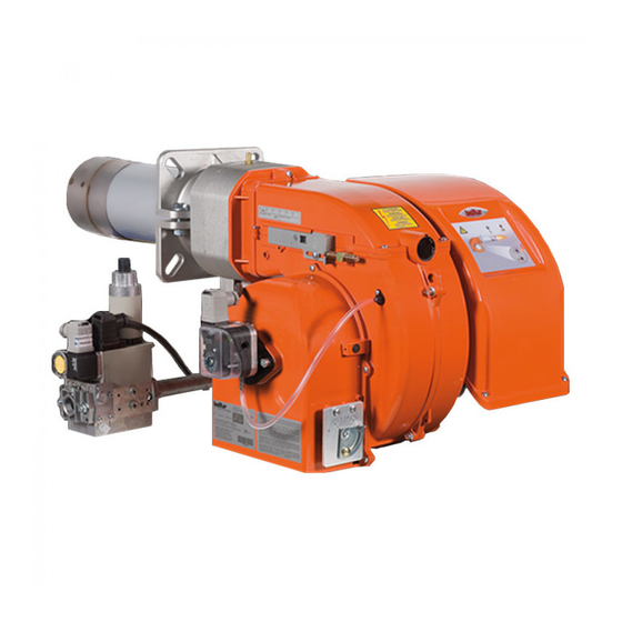
ITALIANO DESCRIZIONE COMPONENTI Testa di combustione Guarnizione Flangia attacco bruciatore Dispositivo regolazione testata Coperchio chiocciola Flangia attacco rampa gas Quadro elettrico Motore Servomotore regolazione aria Regolazione aria manuale Pressostato aria Targa identificazione bruciatore QUADRO ELETTRICO Apparecchiatura Trasformatore d'accensione Contattore motore (Solo con alimentazione trifase) Relè... -
Page 11: Caratteristiche Tecnico Funzionali
ITALIANO CARATTERISTICHE TECNICO FUNZIONALI CARATTERISTICHE COSTRUTTIVE • Possibilità di ottenere ottimi valori di combustione tramite la • Testa di combustione completa di boccaglio in acciaio. regolazione dell'aria comburente e della testa di combustione. • Flangia d'attacco al generatore scorrevole per adattare la •... -
Page 12: Dimensioni Di Ingombro
ITALIANO DIMENSIONI DI INGOMBRO Modello TBG 45 TBG 60 Modello E Ø F Ø LØ N Ø TBG 45 140 ÷ 300 200 ÷ 245 TBG 60 140 - 300 225 - 300 10 / 30 0006081329_201612... -
Page 13: Linea Di Alimentazione
ITALIANO APPLICAZIONE DEL BRUCIATORE ALLA LINEA DI ALIMENTAZIONE Lo schema di principio della linea di alimentazione gas è riportato CALDAIA nella figura sotto. Installare, a monte della valvola gas, una valvola di intercettazione MONTAGGIO GRUPPO TESTATA manuale e un giunto antivibrante, disposti secondo quanto indica- •... -
Page 14: Predisposizione Per Attacco Rampa Verso L'alto
ITALIANO MONTAGGIO RAMPA GAS Sono possibili diverse soluzioni di montaggio (1), (2), (3) , della rampa gas. Il bruciatore viene fornito con attacco per rampa gas rivolto verso il basso. Se si desidera invertire il lato di ingresso rampa per consentire il montaggio della rampa gas secondo la configurazione (1), seguire la procedura descritta al paragrafo:"Predisposizione pre attacco rampa verso l'alto". -
Page 15: Collegamenti Elettrici
ITALIANO COLLEGAMENTI ELETTRICI • Le linee elettriche devono essere distanziate dalle parti calde. • L’installazione del bruciatore è consentita solo in ambienti con grado di inquinamento 2 come indicato nell’allegato M della nor- ma EN 60335-1:2008-07. • Assicurarsi che la linea elettrica a cui si vuol collegare l’appa- recchio sia alimentata con valori di tensione e frequenza adatti al bruciatore. - Page 16 ITALIANO CAUTELA / AVVERTENZE gli alloggiamenti dei cavi per le spine sono previsti rispet- tivamente per cavo Ø 9,5÷10 mm e Ø 8,5÷9 mm, questo per assicurare il grado di protezione IP 44 (Norma CEI EN60529) relativamente al quadro elettrico. Avvitare le viti (1) esercitando una coppia di serraggio adeguata ad assicurare la corretta tenuta, per richiudere il coperchio del quadro elettrico.
-
Page 17: Descrizione Del Funzionamento Tbg 45 - 60
ITALIANO DESCRIZIONE DEL FUNZIONAMENTO TBG 45 - 60 Alla chiusura dell’interruttore generale e dell’interruttore I/O (10) del quadro elettrico, se i termostati sono chiusi, la tensione rag- giunge l’apparecchiatura di comando e controllo che avvia il bru- ciatore (accensione led 7). -
Page 18: Accensione E Regolazione Gas Metano
• per i modelli TBG 45 60 scollegare il filo dal morsetto 5 della morsettiera sul circuito stampato che alimenta la bobina Y2. • Regolare l'aria per la fiamma di accensione: - per il bruciatore TBG 45 - 60 provvisto di regolazione manuale, regolare l’aria per la seconda fiamma seguendo le... - Page 19 ITALIANO • Aprire della quantità che si presume necessaria, il regolatore immediatamente in “blocco”. manuale di portata del gas per la seconda fiamma (fiamma • Verificare l’efficienza dei termostati o pressostati di caldaia (l’in- principale). tervento deve arrestare il bruciatore). •...
-
Page 20: Misurazione Della Corrente Di Ionizzazione
“C”, vedi schema elettrico. 0002935683_45_60 1 - Elettrodo ionizzazione 2 - Elettrodo accensione TBG 45 3 - Disco fiamma TBG 60 4 - Miscelatore 5 - Tubo mandata gas E - ATTENZIONE: uscita foro ugello centrale in prossimità... -
Page 21: Apparecchiatura Di Comando E Controllo Lme
ITALIANO APPARECCHIATURA DI COMANDO E CONTROLLO LME... FUNZIONAMENTO. Il pulsante di sblocco «EK...» è l’elemento principale per poter accedere a ROSSO tutte le funzioni di diagnostica (attivazione e disattivazione), oltre a sbloc- GIALLO care il dispositivo di comando e controllo. VERDE Sia «LED»... - Page 22 ITALIANO DIAGNOSI DELLE CAUSE DI MALFUNZIONAMENTO E BLOCCO. In caso di blocco bruciatore nel pulsante di sblocco sarà fissa la luce rossa. Premendo per più di 3 sec. la fase di diagnosi verrà attivata (luce rossa con lampeggio rapido), nella tabella sottostante viene riportato il significato della causa di blocco o malfunzionamento in funzione del numero di lampeggi (sempre colore rosso).
-
Page 23: Regolazione Dell'aria Sulla Testa Di Combustione
SCHEMA DI REGOLAZIONE ARIA BRUCIATORE TBG 45 - 60 Per regolare l'angolo di apertura della serranda aria, allentare la vite (8) ed agire sul volantino (1) posizionando l'indice nella posi-... -
Page 24: Manutenzione
ITALIANO MANUTENZIONE Effettuare almeno una volta all’anno e comunque in conformità alle norme vigenti, l’analisi dei gas di scarico della combustione verificando la correttezza dei valori di emissioni. • Verificare che tutti i componenti della testa di combustione sia- no in buono stato, non deformati e privi di impurità o depositi derivanti dall'ambiente di installazione e/o da una cattiva com- bustione. -
Page 25: Tempi Di Manutenzione
ITALIANO TEMPI DI MANUTENZIONE TESTA DI COMBUSTIONE CONTROLLO VISIVO, INTEGRITA CERAMICHE. SMERIGLIATURA ESTREMITA, ELETTRODI ANNUO VERIFICARE DISTANZA, VERIFICARE CONNESSIONE ELETTRICA. DISCO FIAMMA CONTROLLO VISIVO INTEGRITA EVENTUALI DEFORMAZIONI, PULIZIA, ANNUO CONTROLLO VISIVO, INTEGRITA CERAMICHE. SMERIGLIATURA ESTREMITA, SONDA DI IONIZZAZIONE ANNUO VERIFICARE DISTANZA, VERIFICARE CONNESSIONE ELETTRICA. COMPONENTI TESTA COMBUSTIONE CONTROLLO VISIVO INTEGRITA EVENTUALI DEFORMAZIONI, PULIZIA, ANNUO... -
Page 26: Precisazioni Sull'uso Del Propano
ITALIANO PRECISAZIONI SULL'USO DEL PROPANO PERICOLO / ATTENZIONE La potenza massima e minima (kW) del bruciatore, è consi- • Valutazione, indicativa, del costo di esercizio; derata con combustibile metano che coincide approssimati- - 1 m3 di gas liquido in fase gassosa ha un potere calorifico vamente con quella del propano. -
Page 27: Schema Di Principio Per Riduzione Pressione G.p.l. A Due Stadi Per Bruciatore Oppure Caldaia
ITALIANO SCHEMA DI PRINCIPIO PER RIDUZIONE PRESSIONE G.P.L. A DUE STADI PER BRUCIATORE OPPURE CALDAIA Manometro e presa di pressione Riduttore di 1° salto Riduttore di 2° salto Uscita ~ 1,5 bar Uscita ~ 30 hPa (mbar) Portata ~ il doppio del massimo richiesto Portata ~ il doppio del massimo richiesto dall’utilizzatore dall’utilizzatore... -
Page 28: Istruzioni Montaggio Riduzioni Per Gpl
TBG 45 previste per il combustibile GPL. TBG 60 1) Dopo aver allentato le viti di fissaggio 1 rimuovere le riduzioni A (N.2) dalle rispettive sedi. -
Page 29: Istruzioni Per L'accertamento Delle Cause Di Irregolarità Nel Funzionamento E La Loro Eliminazione
ITALIANO ISTRUZIONI PER L'ACCERTAMENTO DELLE CAUSE DI IRREGOLARITÀ NEL FUNZIONA- MENTO E LA LORO ELIMINAZIONE POSSIBILE CAUSA RIMEDIO IRREGOLARITÁ Invertire l'alimentazione (lato 230V) del trasformatore di accensione e verificare Disturbo della corrente di ionizza- con micro-amperometro analogico. zione da parte del trasformatore di Sostituire il sensore fiamma. -
Page 30: Schemi Elettrici
ITALIANO SCHEMI ELETTRICI 28 / 30 0006081329_201612... - Page 31 ITALIANO 29 / 30 0006081329_201612...
- Page 32 ITALIANO GNYE VERDE / GIALLO APPARECCHIATURA CONTROLLO TENUTA VALVOLE FOTORESISTENZA / ELETTRODO DI IONIZZAZIONE / BRUNO FOTOCELLULA UV NERO SPIA BLOCCO ESTERNA / LAMPADA FUNZIONAMEN- CONNETTORE NERO CON SOVRASTAMPA TO RESISTENZE AUSILIARIE SPIA DI FUNZIONAMENTO “SPIA DI BLOCCO“ CONTATTORE MOTORE VENTOLA MOTORE VENTOLA “CONTAORE“...
- Page 33 Natural gas ignition and regulation ................................16 Ionisation current measurement ..............................18 Control and command equipment LME..............................19 Air regulation on the combustion head ............................21 TBG 45 - 60 burner air regulation diagram ............................21 Maintenance ......................................22 Maintenance time ....................................23 Specifications for propane use ................................24 Diagram illustrating the principle of L.P.G.
- Page 34 ENGLISH DECLARATION OF CONFORMITY CE0085: DVGW CERT GmbH, Josef-Wirmer Strasse 1-3-53123 Bonn (D) We hereby declare under our own responsibility, that our domestic and industrial blown air burners fired by gas, oil and dual fuel, series: BPM...; BGN…; BT…; BTG…; BTL…; TBML...; Comist…; GI…; GI…Mist; Minicomist…; PYR…; RiNOx…; Spark...; Sparkgas...; TBG...;TBL...;...
- Page 35 ENGLISH INSTRUCTIONS FOR USE IN SAFE through the intermediation of a responsible person, of infor- mation regarding their safety, of surveillance, of instructions CONDITIONS concerning its use. • Children should be supervised to ensure that they do not play PURPOSE OF THE MANUAL with the device.
- Page 36 Contact only qualified personnel. air flow to optimise the combustion performance and emis- • Any product repairs must only be carried out by BALTUR autho- sions according to the regulations in force. rised assistance centres or its local retailer using only original - Check the regulation and safety devices are working spare parts.
- Page 37 ENGLISH Special instructions for using gas. to the burner. • Check that the feed line and the train comply with current stan- • The use of any components that use electricity means that cer- dards and regulations. tain fundamental rules have to followed, including the following: •...
- Page 38 ENGLISH TECHNICAL SPECIFICATIONS MODEL TBG 45 TBG 60 MAXIMUM NATURAL GAS HEAT POWER MINIMUM NATURAL GAS HEAT POWER mg/kWh ¹) NATURAL GAS EMISSIONS Class 3 Class 3 OPERATION One stage One stage NATURAL GAS TRANSFORMER 50 Hz 26 kV - 40 mA - 230/240 V...
- Page 39 ENGLISH MATERIAL PROVIDED TO SECURE THE BURNER TO THE BOILER MODEL TBG 45 TBG 60 SUPPLIED MATERIAL BURNER CONNECTION FLANGE INSULATING SEAL STUD BOLTS N° 4 M 12 N° 4 M 12 HEXAGONAL NUTS N° 4 M 12 N° 4 M 12...
- Page 40 ENGLISH COMPONENT DESCRIPTION Combustion head Seal Burner connection flange Combustion head adjustment device Screw-nut cover Gas train connector flange Electrical panel Motor Air regulation servomotor Manual air regulation system Air pressure switch Burner identification plate ELECTRICAL PANEL Control box Ignition transformer Motor contactor (Only for three-phase power supply) Thermal Relay (Only for three-phase power supply) 7-pole connector...
- Page 41 ENGLISH TECHNICAL FUNCTIONAL CHARACTERISTICS DESIGN CHARACTERISTICS • Possibility to obtain great combustion values through combus- • Combustion head complete with stainless steel nozzle. tion air and combustion head regulation. • Sliding generator connection flange to adapt the head protru- • Air pressure switch to ensure the comburent air presence. sion to the various types of heat generators.
- Page 42 ENGLISH OVERALL DIMENSIONS Model TBG 45 TBG 60 Model E Ø F Ø LØ N Ø TBG 45 140 ÷ 300 200 ÷ 245 TBG 60 140 - 300 225 - 300 10 / 30 0006081329_201612...
- Page 43 ENGLISH BURNER CONNECTION TO THE BOILER SUPPLY LINE The basic diagram of the gas supply line is shown in the figure below. ASSEMBLING THE HEAD UNIT A manual shut off valve and an anti-vibration joint must be ins- • Position insulating seal -13 on the sleeve, placing rope -2 talled upstream of the gas valve, as shown in the diagram.
- Page 44 ENGLISH ASSEMBLING THE GAS TRAIN The gas train can be assembled in different ways: -1, -2, -3 , of the gas train. The burner is supplied by the gas train connection facing downward. If you wish to invert the direction of train entrance to allow the gas train to be assembled in configuration (1), follow the procedure described in the section entitled: "Preparation for connection with train turned upward".
- Page 45 ENGLISH ELECTRICAL CONNECTIONS • Electrical lines must be kept away from hot parts. • The burner installation is allowed only in environments with pollution degree 2 as indicated in annex M of the EN 60335- 1:2008-07 regulation. • Make sure that the electric line to which the unit will be connec- ted has frequency and voltage ratings suitable for the burner.
- Page 46 ENGLISH CAUTION / WARNING The housings for the cables for the 7 and 4-pole plugs are provided respectively for cable Ø 9.5÷10 mm and Ø 8.5÷9 mm, this ensures the protection rating is IP 44 (Standard IEC EN60529) for the electrical panel. Screw the screws (1) with adequate torque to ensure a correct seal to reclose the electrical panel lid.
- Page 47 ENGLISH DESCRIPTION OF TBG 45 / 60 OPERATION When the main switch and the I/O switch -10 on the electrical panel are turned on, if the thermostats are on, voltage reaches the command and control device, which starts up the burner (LED 7 comes on).
- Page 48 • for TBG 45 60 burners, disconnect the wire from terminal 5 on the terminal board on the printed circuit supplying coil Y2. • Regulate air for the ignition flame:...
- Page 49 ENGLISH • Open the manual gas flow rate regulator for the second flame outgoing air speed is so high that ignition is difficult. If this (main flame) to the necessary extent. happens, the mixer must be gradually shifted back until it is •...
- Page 50 “C”, see wiring diagram. 0002935683_45_60 1 - Ionisation electrode 2 - Ignition electrode TBG 45 3 - Flame disk TBG 60 4 - Mixer 5 - Gas delivery pipe E - WARNING: central nozzle hole outlet near the electrode tip.
- Page 51 ENGLISH CONTROL AND COMMAND EQUIPMENT LME... OPERATION. The reset button «EK...» is the main element to access all diagnostic func- tions (activation and deactivation), and serves to unlock the command and YELLOW control device. GREEN Both «LED» and «EK...» are positioned under the transparent button. Pressing this button, you can reset the control box. Possibility of two diagnostic functions: 1.
- Page 52 ENGLISH MALFUNCTION AND LOCK CAUSE DIAGNOSTICS. In the event of a burner lock-out, the red light on the reset button will be fixed. Keeping it pressed in for more than 3 seconds, the diagnostics procedure is activated (red light with quick flashes). The table below indi- cates the meaning of the lock-out or failure according to the number of red flashes.
- Page 53 TBG 45 - 60 BURNER AIR REGULATION DIAGRAM To adjust the opening angle of the air shutter, loosen the screw -8 and turn the hand wheel -1 to bring the index to the desired posi- tion.Subsequently tighten the screw to lock the shutter.
- Page 54 ENGLISH MAINTENANCE Analyse combustion gases and check that the emission values are correct at least once a year, in compliance with current law. • Check that all components of the combustion head are in good condition, have not been deformed and are free from deposits deriving from the installation environment and/or from poor combustion.
- Page 55 ENGLISH MAINTENANCE TIME COMBUSTION HEAD VISUAL INSPECTION OF THE INTEGRITY OF CERAMICS. TIP GRINDING, ELECTRODES YEARLY CHECK DISTANCE, CHECK ELECTRICAL CONNECTION. FLAME DISK INTEGRITY VISUAL INSPECTION FOR POSSIBLE WARPING, CLEANING YEARLY VISUAL INSPECTION OF THE INTEGRITY OF CERAMICS. TIP GRINDING, IONISATION PROBE YEARLY CHECK DISTANCE, CHECK ELECTRICAL CONNECTION.
- Page 56 ENGLISH SPECIFICATIONS FOR PROPANE USE DANGER / CAUTION The burner's minimum and maximum output (kW) is rated • Operating costs approximate assessment; based on its use with methane gas which more or less cor- - 1 m3 of liquid gas in gaseous stage has a lower heating responds to the power values obtained with propane gas.
- Page 57 ENGLISH DIAGRAM ILLUSTRATING THE PRINCIPLE OF L.P.G. PRESSURE REDUCTION IN TWO STAGES FOR BURNER OR BOILER Pressure gauge and pressure intake 1st step reducer 2nd step reducer Output ~ 1.5 bar Output ~ 30 hPa (mbar) Flow rate ~ double the maximum required by the Flow rate ~ double the maximum required by user the user...
- Page 58 TBG 45 for LPG fuel. TBG 60 1) After loosening the fastening screws 1 remove the two reducers A from their respective seats.
- Page 59 ENGLISH TROUBLESHOOTING INSTRUCTIONS POSSIBLE CAUSE REMEDY ANOMALY Invert the ignition transformer power supply (230V side) and check using an Disturbance to ionisation current analogue micro-ammeter. from the ignition transformer. Replace flame sensor. Flame sensor (ionisation probe) Correct the position of the flame sensor, inefficient.
- Page 60 ENGLISH WIRING DIAGRAMS 28 / 30 0006081329_201612...
- Page 61 ENGLISH 29 / 30 0006081329_201612...
- Page 62 ENGLISH GNYE GREEN / YELLOW EQUIPMENT VALVE SEAL CONTROL BLUE PHOTORESISTOR / IONISATION ELECTRODE / UV BROWN PHOTOCELL BLACK EXTERNAL LOCK INDICATOR LIGHT/ AUXILIARY BLACK CONNECTOR WITH OVERPRINT HEATING ELEMENT OPERATION LAMP OPERATION INDICATOR LIGHT “LOCK-OUT INDICATOR LIGHT“ FAN MOTOR CONTACTOR FAN MOTOR “HOUR METER“...
- Page 64 BALTUR S.P.A. Via Ferrarese, 10 44042 Cento (Fe) - Italy Tel. +39 051-6843711 Fax. +39 051-6857527/28 www.baltur.it info@baltur.it Il presente catalogo riveste carattere puramente indicativo. La casa, pertanto, si riserva ogni possibilità di modifica dei dati tecnici e di quant'altro in esso riportato.
Need help?
Do you have a question about the TBG 45 and is the answer not in the manual?
Questions and answers