
Related Manuals for Vecow MIG-2000


Summary of Contents for Vecow MIG-2000
- Page 1 USER USER MIG-2000 Manual Manual 10th Gen Intel ® Core™ i9/i7/i5/i3 Processor AI Computing System NVIDIA ® Tesla ® /Quadro ® /GeForce ® /AMD Graphics 1.0.0 Edition 20210518...
- Page 2 Record of Revision Version Date Page Description Remark 1.00 2021/05/18 Official Release ©Vecow MIG-2000 User Manual...
- Page 3 This manual is released by Vecow Co., Ltd. for reference purpose only. All product offerings and specifications are subject to change without prior notice. Vecow Co., Ltd. is under no legal commitment to the details of this document. Vecow shall not be liable for direct, indirect, special, incidental, or consequential damages arising out of the use of this document, the products, or any third party infringements, which may result from such use.
- Page 4 Order Information GigE PCIe SATA System Model HDMI Tray MIG-2000 ©Vecow MIG-2000 User Manual...
- Page 5 PWS-480W-WT 480W, 24V, 90V AC to 305V AC Power Supply, Wide-Temp, IP65 PWS-600W 600W, 24V, 90V AC to 305V AC Power Supply 600W, 28.8V, 90V to 305V AC Power Supply, Wide Temperature PWS-600W-WT -40°C to +70°C ©Vecow MIG-2000 User Manual...
-
Page 6: Table Of Contents
CHAPTER 1 GENERAL INTRODUCTION 1.1 Overview 1.2 Features 1.3 Specifications of MIG-2000 1.4 Mechanical Dimension CHAPTER 2 GETTING TO KNOW YOUR MIG-2000 2.1 Packing List 2.2 Front Panel I/O Functions 2.3 Main Board Expansion Connectors 2.4 Main Board Expansion Connectors 2.5 Main Board Jumper Settings... - Page 7 4.5 Chipset 4.6 BIOS 4.7 Power 4.8 Save & Exit APPENDIX A : Power Consumption APPENDIX B : Supported Memory & Storage List APPENDIX C : Graphics Benchmark ©Vecow MIG-2000 User Manual...
-
Page 8: Chapter 1 General Introduction
/Quadro /GeForce /AMD Radeon™ Graphics to deliver outstanding computing and graphics performance. Vecow MIG-2000 is equipped with up to 64GB of DDR4 2933 memory and ® features Intel UHD Graphics 630 to support up to 3 HDMI 4K displays and provide 3D graphics quality to deliver breakthrough performance. -
Page 9: Features
• DC 9V to 55V wide range Power Input • Expansion : 1 Mini PCIe, 1 PCIe x16, 1 M.2 Key E • PCIe x16 expansion supports up to 750W Power Budget for independent 2-slot graphics card ©Vecow MIG-2000 User Manual GENERAL INTRODUCTION... -
Page 10: Specifications Of Mig-2000
1.3 Specifications of MIG-2000 System ® Processor 10th Gen Intel Core™ i9/i7/i5/i3 Processor (Comet Lake-S) ® Chipset Intel H410 BIOS Nuvoton NCT6116D Memory 2 DDR4 2933MHz SO-DIMM, up to 64GB I/O Interface Serial 2 COM RS-232/422/485 4 USB 3.0 HDD, Power Expansion 1 M.2 Key E Socket (2230, PCIe) - Page 11 -20°C to 85°C (-4°F to 185°F) Humidity 5% to 95% humidity, non-condensing Relative Humidity 95% at 60°C • IEC 61373 : 2010 Shock • Railway Applications : Rolling Stock Equipment, Shock and Vibration Tests CE, FCC, EN50155, EN50121-3-2 ©Vecow MIG-2000 User Manual GENERAL INTRODUCTION...
-
Page 12: Mechanical Dimension
1.4 Mechanical Dimension Unit : mm (inch) 162.6 (6.40) 385.0 (15.16) 212.6 (8.37) 192.6 (7.58) 162.6 (6.40) R 4.5 (0.18) Ø 5.0 (0.20) ©Vecow MIG-2000 User Manual GENERAL INTRODUCTION... -
Page 13: Chapter 2 Getting To Know Your Mig-2000
GETTING TO KNOW YOUR MIG-2000 2.1 Packing List Item Description MIG-2000 Item Description Outlook Usage PHILLPIS M4x16L with Mount 53-24D6416-30B washer, Ni M3x4 Screw 53-M006350-010 Phillips F-Head M3*5 Wall mount 53-M004950-310 Z.B+Ny M3x4L, Ni M.2 Slot 53-2426204-80B Terminal block 2-pin... -
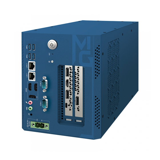
Page 14: Front Panel I/O Functions
2.2 Front Panel I/O Functions In Vecow MIG-2000 series family, all I/O connectors are located on front panel. Most of the general connections to computer device, such as USB, LAN Jack, Audio, COM, HDMI, DC-IN and any additional Graphic Card, are placed on the front panel. - Page 15 Please do note that a 4-second interval between each 2 power-on/ power-off operation is necessary in normal working status. (For example, once turning off the system, you have to wait for 4 seconds to initiate another power-on operation). ©Vecow MIG-2000 User Manual GETTING TO KNOW YOUR MIG-2000...
- Page 16 After installing the HDMI device, make sure to set the default sound playback device to HDMI. (The item name may differ depending on your operating system.) ©Vecow MIG-2000 User Manual GETTING TO KNOW YOUR MIG-2000...
- Page 17 Activity LED State Description State Description Data transmission or Orange 1 Gbps data rate Blinking receiving is occurring Green 100Mbps data rate No data transimission or 10Mbps data rate receiving is occurring ©Vecow MIG-2000 User Manual GETTING TO KNOW YOUR MIG-2000...
- Page 18 Each COM header can provide one serial port via an optional COM port cable. For purchasing the optional COM port cable, please contact the local dealer. Pin No. Definition Pin No. Definition NDCD- NDSR- NSIN NRTS- NSOUT NCTS- NDTR- 12V_5V ©Vecow MIG-2000 User Manual GETTING TO KNOW YOUR MIG-2000...
- Page 19 2.2.9 DC-in This 2-pin DC-IN support 9V~55V DC power input. ©Vecow MIG-2000 User Manual GETTING TO KNOW YOUR MIG-2000...
-
Page 20: Main Board Expansion Connectors
2.3 Main Board Expansion Connectors 2.3.1 Inside View of MIG-2000 Main Board with Connector Location F_AUDIO SPKR ATX_12V AT_ATX CLR_CMOS F_PANEL SPEAKER SATA3 0 SATA3 1 GPIO F_USB2 COMB F_USB1 COMA U_SIM COMB_PW SATA_PWR VOLUME_CONTROL COMA_PW BOOT COMC COMD COMC_PW/... - Page 21 LED, hard drive activity LED and etc. When connecting your chassis front panel module to this header, make sure the wire assignments and the pin assignments are matched correctly. ©Vecow MIG-2000 User Manual GETTING TO KNOW YOUR MIG-2000...
- Page 22 The headers conform to USB 2.0/1.1 specification. Each USB header can provide two USB ports via an optional USB bracket. For purchasing the optional USB bracket, please contact the local dealer. ©Vecow MIG-2000 User Manual GETTING TO KNOW YOUR MIG-2000...
- Page 23 Note : The connector is on the back of the motherboard. 2.3.6 SATA_PWR (SATA Power Connector) This connector provides power to installed SATA devices. SATA_PWR Pin No. Definition Pin No. Definition +12V ©Vecow MIG-2000 User Manual GETTING TO KNOW YOUR MIG-2000...
- Page 24 Overheating may result in damage to the CPU or the system may hang. • These fan headers are not configuration jumper blocks. Do not place a jumper cap on the headers. ©Vecow MIG-2000 User Manual GETTING TO KNOW YOUR MIG-2000...
- Page 25 For information about connecting the front panel audio module that has different wire assignments, please contact the chassis manufacturer. 2.3.11 M.2 (M.2 Socket 3 Connector) The M.2 connector supports M.2 SATA SSDs and M.2 PCIe SSDs. ©Vecow MIG-2000 User Manual GETTING TO KNOW YOUR MIG-2000...
- Page 26 Pin No. Definition NDCD- NDSR- NSIN NRTS- NSOUT NCTS- NDTR- 12V_5V 2.3.13 U_SIM This connector can be used to install a Micro Sim card to connect to a mini-PCIe LAN card. U_SIM ©Vecow MIG-2000 User Manual GETTING TO KNOW YOUR MIG-2000...
- Page 27 RXO3_C +RXO3_C RXECLKO_C +RXECLKO_C RXE0_C +RXE0_C RXE1_C +RXE1_C RXE2_C +RXE2_C (Note) CABLE_DET -RXE3_C +RXE3_C -RXECLKE_C +RXECLKE_C SC_BKLT_EN SC_BKLT_CTL FPD_PWR FPD_PWR FPD_PWR Note : Connects to the ground pin of the LVDS. ©Vecow MIG-2000 User Manual GETTING TO KNOW YOUR MIG-2000...
- Page 28 The header conforms to FPD specification. Pin No. Definition BKLT_EN BKLT_PWM BKLT_PWR (FPD_PWR) BKLT_PWR (FPD_PWR) BKLT_GND/Brightness_GND BKLT_GND/Brightness_GND Brightness_Up Brightness_Down 2.3.17 I2C (Inter-Integrated Circuit) This header provides the I2C signals. Pin No. Definition I2C_SCL I2C_SDA ©Vecow MIG-2000 User Manual GETTING TO KNOW YOUR MIG-2000...
- Page 29 This speaker header is connected to a L/R audio pins from the board to support the 3W (4ohm) stereo speaker on your AIO chassis. SPKR Pin No. Definition Pin No. Definition Speaker OUT R- Speaker OUT R+ Speaker OUT L- Speaker OUT L+ ©Vecow MIG-2000 User Manual GETTING TO KNOW YOUR MIG-2000...
- Page 30 The header connects to the volume control button of the monitor to control the volume. VOLUME_CONTROL Pin No. Definition VOL_DOWN VOL_UP 2.3.21 MON_SW This header allows you to connect an on/off switch for the display. MON_SW Pin No. Definition Mon_SW SMB_DATA ©Vecow MIG-2000 User Manual GETTING TO KNOW YOUR MIG-2000...
- Page 31 2.3.23 STB/BOOT (Status LEDs) If the STB LED is on, that means the system is in standby mode; if the BOOT LED is on, that means the system is powered on. BOOT ©Vecow MIG-2000 User Manual GETTING TO KNOW YOUR MIG-2000...
-
Page 32: Main Board Expansion Connectors
2.4 Main Board Expansion Connectors 2.4.1 Top View (Component Side) of MIG-2000-BP Backplane With Connector Location HDD_PWR_J1 MB_OUT HDD_PWR_J2 GPU_OUT FAN1 2.4.1.1 CN1 : PCIe x16 slot This backplane has one PCI Express 3.0/2.0 x16 slot (with PCIe Gen3 x8 lane) that supports PCI Express 3.0/2.0 x16 graphics cards complying with the PCI... - Page 33 Pin No. Definition +12V +12V +12V +12V 2.4.1.5 FAN1 : Fan Connector Pin No. Fuction +12V (2A max) 2.4.1.6 HDD_PWR_J1, HDD_PWR_J2 : SATA Power Connector Pin No. Definition Pin No. Definition +12V ©Vecow MIG-2000 User Manual GETTING TO KNOW YOUR MIG-2000...
- Page 34 2.4.2 DC- in Board Connectors MIG-2000-DCB support 9V~55V DC power input by wire-to-board connector on the top side. 2.4.2.1 CN1 : DC Input Power Connector Pin No. Definition 2.4.2.2 CN2 : DC Output Power Connector Pin No. Definition DC_OUT ©Vecow MIG-2000 User Manual...
- Page 35 +12V +12V +12V +12V +12V +12V SYS FAN : Fan Connector 2.4.3.3 The pin assignments of SYS FAN is listed in the following table. Pin No. Definition Pin No. Definition +12V ©Vecow MIG-2000 User Manual GETTING TO KNOW YOUR MIG-2000...
-
Page 36: Main Board Jumper Settings
To "open" a jumper, you remove the clip. Sometimes a jumper will have three pins, labeled 1, 2 and 3. In this case you would connect either pins 1 and 2, or 2 and 3. Open Closed Closed 2-3 ©Vecow MIG-2000 User Manual GETTING TO KNOW YOUR MIG-2000... - Page 37 To clear the CMOS values, use a metal object like a screwdriver to touch the two pins for a few seconds. Open : Normal Short : Clear CMOS Values ©Vecow MIG-2000 User Manual GETTING TO KNOW YOUR MIG-2000...
-
Page 38: Chapter 3 System Setup
SYSTEM SETUP 3.1 How to Open Your MIG-2000 Step 1 Remove Top Cover ten M3x5L screws. Step 2 Fisish. ©Vecow MIG-2000 User Manual SYSTEM SETUP... -
Page 39: Installing Ddr4 So-Dimm Modules
3.2 Installing DDR4 SO-DIMM Modules Step 1 Install DDR4 RAM module into SO-DIMM slot. Step 2 Make sure the RAM module is locked by the memory slot. ©Vecow MIG-2000 User Manual SYSTEM SETUP... -
Page 40: Installing M.2 (Key M)
3.3 Installing M.2 (Key M) Step 1 Install M.2 card into the M.2 slot. Step 2 Fasten one M3 screw. ©Vecow MIG-2000 User Manual SYSTEM SETUP... -
Page 41: Installing Pci/Pcie Card
3.4 Installing PCI/PCIe Card Step 1 Please align the gold finger of the PCIe card with the slot. Step 2 Press down the graphics card. ©Vecow MIG-2000 User Manual SYSTEM SETUP... - Page 42 Step 3 Lock screw. Step 4 Finish. ©Vecow MIG-2000 User Manual SYSTEM SETUP...
-
Page 43: Installing Ssd/Hdd
3.5 Installing SSD/HDD Step 1 Open HDD/SSD tray. Step 2 Push the HDD/SSD into the slot. ©Vecow MIG-2000 User Manual SYSTEM SETUP... - Page 44 Step 3 Fasten four M3 screw. ©Vecow MIG-2000 User Manual SYSTEM SETUP...
-
Page 45: Mount Your Mig-2000
3.6 Mount Your MIG-2000 Step 1 Ensure the screw holes on the right and left side of upper case match the ones on MIG-2000 wall mount bracket. Step 2 Fasten Six M3 screws then finish. ©Vecow MIG-2000 User Manual SYSTEM SETUP... -
Page 46: Installing Hold-Down Kit
3.7 Installing Hold-down Kit Hold-down Kit Step 1 Hold two brackets to the graphics card. Step 2 Fasten four M3 screws. ©Vecow MIG-2000 User Manual SYSTEM SETUP... -
Page 47: Chapter 4 Bios Setup
BIOS SETUP 4.1 Entering BIOS Setup Figure 4-1 : Entering Setup Screen The following startup Logo screen will appear when the computer boots. ©Vecow MIG-2000 User Manual BIOS SETUP... -
Page 48: Main Menu
Save all the changes and exit the BIOS Setup program <F12> Capture the current screen as an image and save it to your USB drive <Esc> Main Menu : Exit the BIOS Setup program Submenus : Exit current submenu ©Vecow MIG-2000 User Manual BIOS SETUP... -
Page 49: System
Sets the system time. The time format is hour, minute, and second. For example, 1 p.m. is 13:00:00. Use <Enter> to switch between the Hour, Minute, and Second fields and use the <Page Up> or <Page Down> key to set the desired value. ©Vecow MIG-2000 User Manual BIOS SETUP... -
Page 50: Peripherals
CI header. If the system chassis cover is removed, this field will show "Yes", otherwise it will show "No". To clear the chassis intrusion status record, set Reset Case Open Status to Enabled, save the settings to the CMOS, and then restart your system. ©Vecow MIG-2000 User Manual BIOS SETUP... - Page 51 Enables or disables IPv4 PXE Support. This item is configurable only when Network Stack is enabled. IPv4 HTTP Support Enables or disables HTTP boot support for IPv4. This item is configurable only when Network Stack is enabled. ©Vecow MIG-2000 User Manual BIOS SETUP...
- Page 52 Enables or disables support for external SATA devices. Intel(R) Gigabit Network Connection (LANB) This sub-menu provides information on LAN configuration and related configuration options. Intel(R) Ethernet Connection (LANA) This sub-menu provides information on LAN configuration and related configuration options ©Vecow MIG-2000 User Manual BIOS SETUP...
-
Page 53: Chipset
Audio Controller Enables or disables the onboard audio function. (Default : Enabled) If you wish to install a 3rd party add-in audio card instead of using the onboard audio, set this item to Disabled. ©Vecow MIG-2000 User Manual BIOS SETUP... - Page 54 IOAPIC 24-119 Entries Enables or disables this function. (Default : Enabled) Aperture Size Allows you to set the maximum amount of system memory that can be allocated to the graphics card. (Default : 256MB) ©Vecow MIG-2000 User Manual BIOS SETUP...
-
Page 55: Bios
"UEFI:"string. Or if you want to install an operating system that supports GPT partitioning such as Windows 10 64-bit, select the optical drive that contains the Windows 10 64-bit installation disc and is prefixed with "UEFI:" string. ©Vecow MIG-2000 User Manual BIOS SETUP... - Page 56 Allows you to select the operating system to be installed. (Default : Windows 10) CSM Support Enables or disables UEFI CSM (Compatibility Support Module) to support a legacy PC boot process. Enabled Enables UEFI CSM. Disabled Disables UEFI CSM and supports UEFI BIOS boot process only. (Default) ©Vecow MIG-2000 User Manual BIOS SETUP...
- Page 57 Note : Before setting the User Password, be sure to set the Administrator Password first. Secure Boot Allows you to enable or disable Secure Boot and configure related settings. This item is configurable only when CSM Support is set to Disabled. ©Vecow MIG-2000 User Manual BIOS SETUP...
-
Page 58: Power
Watch Dog Enables or disables Watch Dog function. (Default : Disabled) RC6 (Render Standby) Allows you to determine whether to let the onboard graphics enter standby mode to decrease power consumption. (Default : Enabled) ©Vecow MIG-2000 User Manual BIOS SETUP... -
Page 59: Save & Exit
Select File in HDD/FDD/USB to input the profile previously created from your storage device or load the profile automatically created by the BIOS, such as reverting the BIOS settings to the last settings that worked properly (last known good record). ©Vecow MIG-2000 User Manual BIOS SETUP... -
Page 60: Appendix A : Power Consumption
SATA 1 Seagate HDD 500GB LAN 1 (i219) 1.0 Gbps LAN 2 (i211) 1.0 Gbps Graphics Output HDMI Power Plan Balance (Windows10 Power plan) Power Source Chroma 62006P-100-25 Test Program-1 BurnInTest Test Program-2 FurMark ©Vecow MIG-2000 User Manual Appendix A... - Page 61 Run 100% CPU Power usage with 2D usage with 3D Input Current Consumption Current Consumption 5.013A 60.16W 5.102A 61.22W 2.618A 62.83W 2.665A 63.96W Core™ i7- 10700TE 1.982A 71.35W 1.842A 66.31W 1.206A 66.33W 1.226A 67.43W ©Vecow MIG-2000 User Manual Appendix A...
- Page 62 Run 100% CPU Power usage with 2D usage with FurMark Input Current Consumption Current Consumption 5.095A 61.14W 5.162A 61.94W 2.656A 63.74W 2.676A 64.22W Core™ i9- 10900TE 1.833A 65.99W 1.847A 66.49W 1.116A 61.38W 1.178A 64.79W ©Vecow MIG-2000 User Manual Appendix A...
- Page 63 Run 100% CPU Power usage with 2D usage with FurMark Input Current Consumption Current Consumption 6.942A 83.30W 8.542A 102.51W 3.667A 88.01W 4.668A 112.03W Core™ i5- 10500E 2.555A 91.98W 3.199A 115.16W 1.763A 96.97W 2.267A 124.69W ©Vecow MIG-2000 User Manual Appendix A...
- Page 64 Run 100% CPU Power usage with 2D usage with FurMark Input Current Consumption Current Consumption 7.299A 87.59W 39.125A 469.50W 3.655A 87.72W 17.963A 431.10W Core™ i9- 10900TE 2.529A 91.04W 12.312A 443.23W 1.887A 103.79W 8.288A 455.84W ©Vecow MIG-2000 User Manual Appendix A...
-
Page 65: Appendix B : Supported Memory & Storage List
SL LINK 16GB DDR4-3200 SODIMM J4AGSH1G8TMFC 25ºC SL LINK 32GB DDR4-3200 SODIMM J4BGSH2G8TMFC 25ºC Innodisk 16GB DDR4-3200 SODIMM M4S0-AGS1OCEM-H03 25ºC Innodisk 16GB DDR4-3200 SODIMM M4S0-AGS1O5EM-H03 25ºC Innodisk 32GB DDR4-3200 SODIMM M4S0-BGS2OCEM-H03 25ºC Innodisk 32GB DDR4-3200 SODIMM M4S0-BGS2O5EM-H03 25ºC ©Vecow MIG-2000 User Manual Appendix B... - Page 66 Innodisk DEM28-01TDK1ECAQF-H03 M.2 (P80) 3TE6 DEM28-01TDD1ECAQF-H03 Innodisk M.2 (P80) 3TG3-P DGM28-02TDA1ECBEH-H03 760P INTEL 128GB SSDPEKKW128G8 M.2 PCIe 970 EVO PLUS SAMSUNG 250GB MZ-V7S250 FORESEE FSGPMMC-256G 256GB TOSHIBA KXG50ZNV512G 512GB SA1000M8 240GB Kingston SA2000MB 500GB ©Vecow MIG-2000 User Manual Appendix B...
-
Page 67: Appendix C : Graphics Benchmark
Night Raid Score 43895 44429 Graphics score 102258 105960 Night Raid (V1.1) CPU score 10367 10355 Resolution (screen) 3840 x 2160 3840 x 2160 ** If more help is needed, please contact Vecow Technical Support. ©Vecow MIG-2000 User Manual Appendix C... - Page 68 No part of this publication may be reproduced in any form or by any means, electric, photocopying, or recording, without prior authorization from the publisher. The rights of all the brand names, product names, and trademarks belong to their respective owners. © Vecow Co., Ltd. 2021. All rights reserved.
Need help?
Do you have a question about the MIG-2000 and is the answer not in the manual?
Questions and answers