
Related Manuals for Vecow ECS-4500


Summary of Contents for Vecow ECS-4500
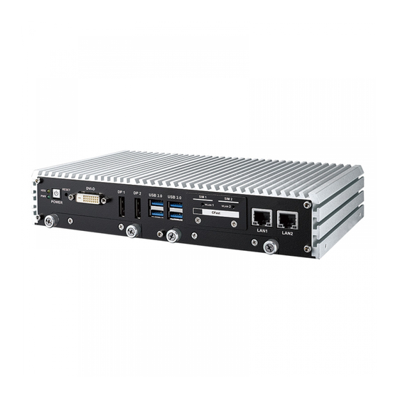
- Page 1 USER USER ECS-4500 Manual Manual Intel ® Core™ i7/i5/i3 SoC Slim Fanless Embedded System IEEE 802.3at PD/PoE , High Performance, Rugged, -25°C to 70°C 1.1.0 Edition 20170331...
- Page 2 Record of Revision Version Date Page Description Remark 03/31/2017 Official Release...
- Page 3 This manual is released by Vecow Co., Ltd. for reference purpose only. All product offerings and specifications are subject to change without prior notice. It does not represent commitment of Vecow Co., Ltd. Vecow shall not be liable for direct, indirect, special, incidental, or consequential damages arising out of the use of the product or documentation or any infringements upon the rights of third parties, which may result from such use.
- Page 4 Order Information Part Number Description ® ECS-4500, Intel Core™ i7-6600U Processor, 6 GigE LAN w/4 ECS-4500- , 2 SSD Tray, 5 USB 3.0, 4 COM, 2 SIM, 16 Isolated DIO, PoER600U 16 GPIO ® ECS-4500, Intel Core™ i5-6300U Processor, 6 GigE LAN w/4 ECS-4500- , 2 SSD Tray, 5 USB 3.0, 4 COM, 2 SIM, 16 Isolated DIO,...
- Page 5 Order Accessories Part Number Description DDR4 16G Certified DDR4 16GB 2133MHz RAM DDR4 8G Certified DDR4 8GB 2133MHz RAM DDR4 4G Certified DDR4 4GB 2133MHz RAM 160W, 24V, 85V AC to 264V AC Power Adapter with 3-pin PWA-160W-WT Terminal Block, Wide Temperature -30°C to +70°C 120W, 24V, 90V AC to 264V AC Power Adapter with 4-pin PWA-120WM4P Mini-DIN Connector...
-
Page 6: Table Of Contents
1.5.3 Dimensions of ECS-4500-PDR 1.5.4 Dimensions of ECS-4500-PD 1.5.5 Dimensions of ECS-4500-2R 1.5.6 Dimensions of ECS-4500-2G CHAPTER 2 GETTING TO KNOW YOUR ECS-4500 2.1 Packing List 2.2 Front Panel I/O Functions 2.3 Rear Panel I/O and Functions 2.4 Main Board Expansion Connectors 2.5 Main Board Jumper &... - Page 7 3.3 Installing Mini PCIe Card 3.4 Installing Antenna Cable 3.5 Installing CFast Card 3.6 Installing SIM Card 3.7 Installing SSD/ HDD 3.8 Mounting Your ECS-4500 CHAPTER 4 BIOS SETUP 4.1 Entering BIOS SETUP 4.2 Main 4.3 Advanced 4.4 Chipset 4.5 Security 4.6 Boot...
-
Page 8: Chapter 1 General Introduction
HD Graphics 520 graphics engine supports DirectX 12, OpenGL 4.4 and OpenCL 2.0 API, onboard DVI-D and DisplayPort display interfaces support up to ultra HD 4K resolution, ECS-4500 offers up to 34% improved graphics performance than the former generation; Multiple Gen 3 PCIe (8GT/s), SATA III (6Gbps), USB 3.0 (5Gbps), GigE (1Gbps) LAN and flexible 3G/4G/WiFi/... -
Page 9: Features
• 5 USB 3.0, 4 RS-232/422/485 COM, 2 SATA III, 1 mSATA • 16 Isolated DIO with NPN/PNP, 16 GPIO • 6V to 36V DC Power Input with 80V Surge Protection • Configurable Ignition Power Control with Smart Battery Protection 1.3 Product Specification 1.3.1 Specifications of ECS-4500-PoER System ® ® Processor Intel Core™... - Page 10 Graphics ® Graphics Processor Intel HD Graphics 520 Interface • DVI-D : Up to 1920 x 1200 @ 60Hz • DisplayPort 1 : Up to 4096 x 2304 @ 60Hz • DisplayPort 2 : Up to 4096 x 2304 @ 60Hz Storage SATA 2 SATA III (6Gbps) support S/W RAID 0, 1...
-
Page 11: Specifications Of Ecs-4500-Poe
Shock • IEC 60068-2-27 • SSD : 50G @ Wallmount, Half-sine, 11ms Vibration • IEC 60068-2-64 • SSD : 5Grms, 5Hz to 500Hz, 3 Axis CE, FCC, EN50155, EN50121-3-2 1.3.2 Specifications of ECS-4500-PoE System ® ® Processor Intel Core™ i7-6600U/i5-6300U/Celeron... - Page 12 Expansion Mini PCIe 2 Mini PCIe Socket : • 1 Full-size for PCIe/USB/External SIM Card • 1 Full-size for PCIe/USB/External SIM Card/mSATA Graphics ® Graphics Processor Intel HD Graphics 520 Interface • DVI-D : Up to 1920 x 1200 @ 60Hz •...
-
Page 13: Specifications Of Ecs-4500-Pdr
Shock • IEC 60068-2-27 • SSD : 50G @ Wallmount, Half-sine, 11ms Vibration • IEC 60068-2-64 • SSD : 5Grms, 5Hz to 500Hz, 3 Axis CE, FCC, EN50155, EN50121-3-2 1.3.3 Specifications of ECS-4500-PDR System ® ® Processor Intel Core™ i7-6600U/i5-6300U/Celeron... - Page 14 Power, HDD, Wireless, PD SIM Card 2 SIM Card Socket (External) Expansion Mini PCIe 2 Mini PCIe Socket : • 1 Full-size for PCIe/USB/External SIM Card • 1 Full-size for PCIe/USB/External SIM Card/mSATA Graphics ® Graphics Processor Intel HD Graphics 520 Interface •...
-
Page 15: Specifications Of Ecs-4500-Pd
Shock • IEC 60068-2-27 • SSD : 50G @ Wallmount, Half-sine, 11ms Vibration • IEC 60068-2-64 • SSD : 5Grms, 5Hz to 500Hz, 3 Axis CE, FCC, EN50155, EN50121-3-2 1.3.4 Specifications of ECS-4500-PD System ® ® Processor Intel Core™ i7-6600U/i5-6300U/Celeron... - Page 16 Expansion Mini PCIe 2 Mini PCIe Socket : • 1 Full-size for PCIe/USB/External SIM Card • 1 Full-size for PCIe/USB/External SIM Card/mSATA Graphics ® Graphics Processor Intel HD Graphics 520 Interface • DVI-D : Up to 1920 x 1200 @ 60Hz •...
-
Page 17: Specifications Of Ecs-4500-2R
Shock • IEC 60068-2-27 • SSD : 50G @ Wallmount, Half-sine, 11ms Vibration • IEC 60068-2-64 • SSD : 5Grms, 5Hz to 500Hz, 3 Axis CE, FCC, EN50155, EN50121-3-2 1.3.5 Specifications of ECS-4500-2R System ® ® Processor Intel Core™ i7-6600U/i5-6300U/Celeron... - Page 18 Expansion Mini PCIe 2 Mini PCIe Socket : • 1 Full-size for PCIe/USB/External SIM Card • 1 Full-size for PCIe/USB/External SIM Card/mSATA Graphics ® Graphics Processor Intel HD Graphics 520 Interface • DVI-D : Up to 1920 x 1200 @ 60Hz •...
-
Page 19: Specifications Of Ecs-4500-2G
95% at 70°C Shock • IEC 60068-2-27 • SSD : 50G @ Wallmount, Half-sine, 11ms Vibration • IEC 60068-2-64 • SSD : 5Grms, 5Hz to 500Hz, 3 Axis 1.3.6 Specifications of ECS-4500-2G System ® ® Processor Intel Core™ i7-6600U/i5-6300U/Celeron 3955U Processor (Skylake-U) ®... - Page 20 Graphics ® Graphics Processor Intel HD Graphics 520 Interface • DVI-D : Up to 1920 x 1200 @ 60Hz • DisplayPort 1 : Up to 4096 x 2304 @ 60Hz • DisplayPort 2 : Up to 4096 x 2304 @ 60Hz Storage SATA 2 SATA III (6Gbps) support S/W RAID 0, 1...
-
Page 21: Supported Cpu List
CE, FCC, EN50155, EN50121-3-2 1.4 Supported CPU List Processor No. Cache Max. Frequency Embedded i7-6600U Up to 3.4 GHz i5-6300U Up to 3.0 GHz i3-6100U Up to 2.3 GHz Celeron 3955U Up to 2.0 GHz ©Vecow ECS-4500 User Manual GENERAL INTRODUCTION... -
Page 22: Mechanical Dimension
1.5 Mechanical Dimension 1.5.1 Dimensions of ECS-4500-PoER 293.8 (11.57”) 278.8 (10.98”) 256.8 (10.11”) Unit: mm (inch) 1.5.2 Dimensions of ECS-4500-PoE 293.8 (11.57”) 278.8 (10.98”) 256.8 (10.11”) Unit: mm (inch) 1.5.3 Dimensions of ECS-4500-PDR 293.8 (11.57”) 278.8 (10.98”) 256.8 (10.11”) Unit: mm (inch) -
Page 23: Dimensions Of Ecs-4500-Pd
1.5.4 Dimensions of ECS-4500-PD 293.8 (11.57”) 278.8 (10.98”) 256.8 (10.11”) Unit: mm (inch) 1.5.5 Dimensions of ECS-4500-2R 293.8 (11.57”) 278.8 (10.98”) 256.8 (10.11”) Unit: mm (inch) 1.5.6 Dimensions of ECS-4500-2G 293.8 (11.57”) 278.8 (10.98”) 256.8 (10.11”) Unit: mm (inch) ©Vecow ECS-4500 User Manual... -
Page 24: Chapter 2 Getting To Know Your Ecs-4500
2.1 Packing List Item Description ECS-4500 Slim Fanless Embedded System (According to the configuration of you order, the ECS-4500 series may contain SSD/HDD and DDR4 SO-DIMM. Please verify these items if necessary.) ECS-4500-PoE/PD/2G accessory box, which contains ● Vecow Drivers & Utilities DVD ●... -
Page 25: Front Panel I/O Functions
WLAN CFast POWER LAN1 LAN2 It is a hardware reset switch. Please use this switch to reset ECS-4500 without power off. Press the Reset Switch for a few seconds, and then reset will be enabled. 2.2.2 Power Button Powered SIM 1... - Page 26 It is implemented by a SATA III Port from Skylake-U PCH. Be sure to disconnect the power source and unscrew the CFast socket cover before installing a CFast card. The ECS-4500 does not support the CFast hot swap and PnP (Plug and Play) functions. It is necessary to remove power source first before inserting or removing the CFast card.
- Page 27 HDD LED/Yellow : A hard disk/CFast LED. If the LED is on, it indicates that ECS-4500 storage is functional. If it is off, it indicates that the system’s storage is not functional. If it is flashing, it indicates data access activities.
- Page 28 There are 5 USB 3.0 (4 in the front, 1 in the rear panel) connections available supporting up to 5GB per second data rate of ECS-4500. It is also compliant with the requirements of SuperSpeed (SS), High Speed (HS), Full Speed (FS) and Low Speed (LS).
- Page 29 POWER LAN1 LAN2 There are 2 PD (Powered Device) 8-pin RJ-45 jacks supporting 10/100/1000 Mbps Ethernet connections with PD in the front side of ECS-4500. LAN 1 is ® ® powered by Intel 219LM Ethernet engine and LAN 2 is powered by Intel I210.
- Page 30 Flash Flash Right Yellow Yellow Yellow PD LED indicators as below : Please note to keep enough power when ECS-4500 is working in high performance. Location Status Color Green : POE installed & power in LAN1 Green Off : Non-PoE Green : PD installed &...
-
Page 31: Rear Panel I/O And Functions
LAN4 LAN6 LAN3 LAN5 ECS-4500 supports 6V to 36V DC power input by terminal block in the rear side. In normal power operation, power LED lightens in solid green. Onboard LTC4356 supports up to 80V surge protection. Pin No. Definition Pin No. - Page 32 INPUT 6 SIO_GPI86 INPUT 7 SIO_GPI87 DI1_COM DIO1_GND OUTPUT 0 SIO_GPO70 OUTPUT 1 SIO_GPO71 OUTPUT 2 SIO_GPO72 OUTPUT 3 SIO_GPO73 OUTPUT 4 SIO_GPO74 OUTPUT 5 SIO_GPO75 OUTPUT 6 SIO_GPO76 OUTPUT 7 SIO_GPO77 DIO1_GND DIO1_VDC (6~48V Input) GETTING TO KNOW YOUR ECS-4500...
- Page 33 Sink Mode Device DIO Connector (NPN, Default) 6-48V DC DIO_VDC (Pin 20) DO (Pin11-18) DIO_GND (Pin10,19) Source Mode (PNP) Device DIO Connector 6-48V DC DIO_VDC (Pin 20) DO (Pin11-18) DIO_GND (Pin10,19) ©Vecow ECS-4500 User Manual GETTING TO KNOW YOUR ECS-4500...
- Page 34 RS-232 RS-422 RS-422 RS-485 Port (5-wire) (9-wire) (3-wire) TXD- TXD- DATA- TXD+ TXD+ DATA+ RXD+ RXD+ ----------- RXD- RXD- ----------- 1 to 4 ----------- RTS- ----------- ----------- RTS+ ----------- ----------- CTS+ ----------- ----------- CTS- ----------- GETTING TO KNOW YOUR ECS-4500...
- Page 35 The left LED will keep twinkling/ off when Ethernet data packets are being transmitted/received. LED Status 10Mbps 100Mbps 1000Mbps Right Solid Solid Bottom Led Green Orange Left Flash Flash Flash Bottom Led Yellow Yellow Yellow ©Vecow ECS-4500 User Manual GETTING TO KNOW YOUR ECS-4500...
- Page 36 There are 5 USB 3.0 (4 on the front, 1 on the rear panel) connections available supporting up to 5GB per second data rate in the front/rear side of ECS-4500. It is also compliant with the requirements of Super Speed (SS), High Speed (HS), Full Speed (FS) and Low Speed (LS).
-
Page 37: Main Board Expansion Connectors
2.4 Main Board Expansion Connectors 2.4.1 Top View of ECS-4500 Main Board With Connector Location CN31 CN33 JCOM3 JCOM4 JDIO1 CN10 JDIO2 CN32 CN12 CN13 CN11 CN14 CN16 CN15 CN30 Battery JP14 JP11 JP12 JP13 JP10 2.4.2 Bottom View of ECS-4500 Main Board with Connector Location... - Page 38 The pin-outs of Miscellaneous port are listed in following table: Group Pin No. Description HDD_LED_P HDD LED HDD_LED_N FP_RST_BTN_N RESET BUTTON Ground PWR_LED_P POWER LED PWR_LED_N FP_PWR_BTN_P POWER BUTTON Ground 2.4.4 LVDS CN16 GETTING TO KNOW YOUR ECS-4500...
- Page 39 ECS-4500 supports dual-channel 24-bit LVDS display, up to 1920 x 1200 pixels resolution. The pin assignments of CN16 are listed in the following table: Pin No. Definition Pin No. Definition PANEL_VDD TXO0- TXE0- PANEL_VDD TXO0+ TXE0+ PANEL_VDD TXO1- TXE1- TXO1+...
- Page 40 CN11 CN14 There are 2 onboard high performance Serial ATA III (SATA III) on ECS-4500. It supports higher storage capacity with less cabling effort and smaller required space. The pin assignments of CN11 and CN14 are listed in the following table: Pin No.
- Page 41 2.4.7 Internal USB2.0 The ECS-4500 main board provides 3 expansion USB ports using plug-and- play for Dongle Key or LCD touch Panel. The USB interface supports 480 Mbps transfer rate complied with high speed USB specification Rev. 2.0. The USB interface is accessed through one 4-pin JST 2.0mm connector and one 10-pin JST 1.0mm connector.
- Page 42 1. When a Mini PCIe device is inserted, its pin-43 forces the respective pin on the socket to ground, or logic 0. ECS-4500 using JP7 Pin-43 status designed for switching between mSATA drive and Mini PCIe device.
- Page 43 CN12 The pin assignments of CN12 are listed in the following table: Pin No. Function Pin No. Function Reserved +V3P3aux Reserved Reserved +1.5V Reserved Reserved Reserved +V3P3aux Reserved +V3P3aux USB_D+ USB_D- ©Vecow ECS-4500 User Manual GETTING TO KNOW YOUR ECS-4500...
- Page 44 2.4.10 Battery Battery The ECS-4500 real-time clock is powered by a lithium battery. It is equipped with Panasonic BR2032 190mAh lithium battery. It is recommended that you not replace the lithium battery on your own. If the battery need to be changed, please contact the Vecow RMA service team.
- Page 45 GPI or GPO. JDIO1 and JDIO2 pins are defined in the following table: Pin No. JDIO1 Definition JDIO2 Definition SIO_GP11 SIO_GP37 SIO_GP12 SIO_GP50 SIO_GP15 SIO_GP51 SIO_GP16 SIO_GP52 SIO_GP32 SIO_GP56 SIO_GP33 SIO_GP57 ©Vecow ECS-4500 User Manual GETTING TO KNOW YOUR ECS-4500...
- Page 46 SIO_GP36 SIO_GP65 2.4.13 BIOS Socket CN10 If the BIOS need to be changed, please contact the Vecow RMA service team. 2.4.14 LPC Port 80 Header ECS-4500 provides a LPC Port 80 Header for Debug Card. GETTING TO KNOW YOUR ECS-4500...
- Page 47 2.4.15 External LAN LED Header CN31 CN33 CN32 CN30 ECS-4500 provides LAN LED to indicate LAN status, PoE power on/off and PD power on/off for external chassis use. Header Pin No. Function Pin No. Function LAN1_LINK100# LAN2_LINK100# LAN1_LINK1000# LAN2_LINK1000# CN30...
- Page 48 Header Pin No. Function Pin No. Function LAN5_LINK100# LAN6_LINK100# LAN5_LINK1000# LAN6_LINK1000# CN32 +V3P3_A +V3P3_A LAN5_ACT# LAN6_ACT# Header Pin No. Function Pin No. Function POE_LED0 PWR_POE_LED2 PWR_POE_LED0 POE_LED3 CN33 POE_LED1 PWR_POE_LED3 PWR_POE_LED1 POE_LED2 GETTING TO KNOW YOUR ECS-4500...
-
Page 49: Main Board Jumper & Deep Switch Settings
JP12 JP13 JP10 The figure below is the top view of ECS-4500 board, and it shows the location of the jumpers and the switches. You may configure your card to match the needs of your application by setting jumpers. A jumper is a metal bridge used to close an electric circuit. It consists of two metal pins and a small metal clip (often protected by a plastic cover) that slides over the pins to connect them. - Page 50 RI (Default) +5V (1A max.) COM4 +12V (0.5A max.) RI (Default) 2.5.3 PoE Power ON Select Header Pin No. Function PoE power on at standby power ready PoE power on after system power on (Default) GETTING TO KNOW YOUR ECS-4500...
- Page 51 Spport mSATA interface for Mini PCIe 1 (CN13) 2.5.5 Backlight Control Level Select Header Pin No. Function +V3P3 (Default) 2.5.6 USB Power Jumper JP10 Header Pin No. Function Non Wake Up support JP10 Supported Wake Up(Default) ©Vecow ECS-4500 User Manual GETTING TO KNOW YOUR ECS-4500...
- Page 52 Pin No. Function +V3P3 (Default) JP12 (ME)/ JP13 (CMOS) 2.5.9 DP (DP2) & LVDS Select JP14 Please do note that DP2 will not be enabled when ECS-4500 supports dual- channel 24-bit LVDS display. Header Pin No. Interface DP (DP2) JP14...
-
Page 53: Ignition Control
The built-in MCU monitors the ignition signal and turns on/off the system according to pre-defined on/off delay periods. 2.6.1 Adjust Ignition Control Modes ECS-4500 series provides 16 modes of different power on/off delay periods adjustable via rotary switch. The default rotary switch is set to 0 in ATX/AT power mode. - Page 54 5 seconds 90 seconds 5 seconds 30 minutes 5 seconds 1 hour 10 seconds 2 hours 10 seconds 4 hours 10 seconds 6 hours 10 seconds 8 hours 10 seconds 12 hours 10 seconds 24 hours GETTING TO KNOW YOUR ECS-4500...
- Page 55 Note: 1. DC power source and IGN share the same ground. 2. ECS-4500 supports 6V~36V wide range DC power input in ATX/AT mode. In Ignition mode, the input voltage is fixed to 12V/24V for car battery scenario. 3. For proper ignition control, the power button setting should be “Power down”...
- Page 56 2.6.3 Smart Battery Protection The system with “Ignition Control” can perform Smart Battery Protection, namely Low Battery Detection. When the system is running on a battery and its voltage drops below the threshold, the system will automatically shut down. The Low Battery Detection is implemented in the ignition control MCU FW and as a default function.
-
Page 57: Chapter 3 System Setup
SYSTEM SETUP 3.1 How to Open Your ECS-4500 Step 1 Remove four F#6-32(red) and one KHS#6-32(yellow) screws. Step 2 Remove one KHS#6-32 screws. ©Vecow ECS-4500 User Manual HARDWARE INSTALLATION... - Page 58 Step 3 Take out the bottom. Step 4 Finish. HARDWARE INSTALLATION...
-
Page 59: Installing Ddr4 So-Dimm Modules
3.2 Installing DDR4 SO-DIMM Modules Step 1 Install DDR4 RAM module into SO-DIMM slot. Step 2 Make sure the RAM module is locked by the memory slot. ©Vecow ECS-4500 User Manual HARDWARE INSTALLATION... -
Page 60: Installing Mini Pcie Card
3.3 Installing Mini PCIe Card Step 1 Install Mini PCIe card into the Mini PCIe socket. Step 2 Fasten one M2.5 screw. HARDWARE INSTALLATION... -
Page 61: Installing Antenna Cable
3.4 Installing Antenna Cable Step 1 Check antenna cable and washers. Step 2 Put Antenna cable connector into the hole on rear panel and fasten the washer 1, washer 2 and washer 3 on Antenna cable connector. ©Vecow ECS-4500 User Manual HARDWARE INSTALLATION... -
Page 62: Installing Cfast Card
3.5 Installing CFast Card Step 1 Remove two F-M3 screws on CFast & SIM Card cover. Step 2 Remove CFast & SIM Card cover. Step 3 Before inserting CFast & SIM Card, make sure the system power is not plugged. Step 4 Insert CFast card and push to lock. -
Page 63: Installing Sim Card
Step 1 Remove two F-M3 screws on CFast & SIM Card cover. Step 2 Remove CFast & SIM Card cover. Step 3 Before inserting CFast & SIM Card, make sure the system power is not plugged. Step 4 Insert SIM card and push to lock. ©Vecow ECS-4500 User Manual HARDWARE INSTALLATION... -
Page 64: Installing Ssd/ Hdd
3.7 Installing SSD/ HDD 3.7.1 ECS-4500-PoER/PDR/2R series Step 1 SSD/HDD Tray. Step 2 Fix the SSD/HDD on the tray with two F-M3x4 screws. HARDWARE INSTALLATION... - Page 65 Step 3 Fix with the tray. Step 4 Put the SSD/HDD tray and then clockwisely fasten the locks. ©Vecow ECS-4500 User Manual HARDWARE INSTALLATION...
- Page 66 3.7.2 ECS-4500-PoE/PD/2G series Step 1 Remove eight F-M3 screws. Step 2 Install SSD/HDD with HDD bracket. Step 3 Lock KH-M3 screws.(One SSD/HDD with four KH-M3 screws) HARDWARE INSTALLATION...
-
Page 67: Mounting Your Ecs-4500
3.8.1 Wall Mount Bracket Step 1 Ensure the screw holes on the right and left side of the upper case match the ones on ECS-4500 wall mount bracket. Step 2 Fasten 4pcs KHS#6-32 screws and then finish. Step 3 Finish. - Page 68 3.8.2 VESA Mount Step 1 ECS-4500 and VESA Mount. Step 2 Take ECS-4500 and VESA Mount with fasten four KHS#6-32 screws. Step 3 Finish. HARDWARE INSTALLATION...
- Page 69 3.8.3 Din Rail Kit Step 1 ECS-4500 and Din Rail Kit. Step 2 Take ECS-4500 and Din Rail Kit with fasten four KHS#6-32 screws. Step 3 Finish. ©Vecow ECS-4500 User Manual HARDWARE INSTALLATION...
-
Page 70: Chapter 4 Bios Setup
BIOS SETUP 4.1 Entering BIOS SETUP Figure 4-1: Entering Setup Screen BIOS provides an interface for users to check and change system configuration. The BIOS setup program is accessed by pressing the <Del> key when POST display output is shown. BIOS AND DRIVER SETTING... -
Page 71: Main
Set the time. Use <Tab> to switch between time elements. 4.3 Advanced Figure 4 3: BIOS Advanced Menu Select advanced tab to enter advanced BIOS setup options such as CPU configuration, SATA configuration, and USB configuration. ©Vecow ECS-4500 User Manual BIOS AND DRIVER SETTING... - Page 72 4.3.1 Trusted Computing Figure 4 3-1: Trusted Computing Control the TPM device status and display related information if TPM chip is present. 4.3.2 ACPI Settings Figure 4 3-2: ACPI Settings Enable Hibernation Enables or disables system's ability to hibernate (OS/S4 sleep state). This option may not be effective with some OS.
- Page 73 4.3.4 PCH-FW Configuration Figure 4 3-4: PCH-FW Settings ME Unconfig on RTC Clear State Disabling this option will cause ME not to unconfigure on RTC clear. ME State Set ME to Soft temporarily disabled. ©Vecow ECS-4500 User Manual BIOS AND DRIVER SETTING...
- Page 74 4.3.5 SMART Settings Figure 4 3-5: SMART Settings SMART Self Test Run SMART self test on all HDD’s during POST. 4.3.6 IT8786 Super IO Configuration Figure 4-3-6: Super IO Settings Serial Port 1 Configuration Set parameters of serial port 1 (COM1). Serial Port 2 Configuration Set parameters of serial port 2 (COM2).
- Page 75 Console redirection enable or disable. Console Redirection Settings These settings specify how the host computer and the remote computer (which the user is using) will exchange data. Both computers should have the same or compatible settings. ©Vecow ECS-4500 User Manual BIOS AND DRIVER SETTING...
- Page 76 4.3.9 CPU Configuration Figure 4 3-9: CPU Function Settings Hyper-threading Enabled for Windows XP and Linux (OS optimized for Hyper-Threading Technology) and disabled for other OS (OS not optimized for Hyper-Threading Technology). When disabled, only one thread per core is enabled. Active Processor Cores Number of cores to enable in each processor package.
- Page 77 Package C State limit Package C State limit. Intel TXT(LT) Support Enables or disables Intel (R) TXT (LT) support. 4.3.10 Intel TXT Information Figure 4 3-10: Intel TXT Information Display Intel TXT information. ©Vecow ECS-4500 User Manual BIOS AND DRIVER SETTING...
- Page 78 4.3.11 SATA Configuration Figure 4 3-11: SATA Devices Settings SATA Controller(s) Enable or disable SATA Device. SATA Mode Selection Determines how SATA controller(s) operate. Software Feature Mask Configuration RAID OROM/RST driver will refer to the SWFM configuration to enable or disable the storage features.
- Page 79 4.3.12 Acoustic Management Configuration Figure 4 3-12: Acoustic Management Settings Acoustic Management Configuration Option to enable or disable automatic acoustic management. 4.3.13 CSM Configuration Figure 4 3-13: CSM Settings ©Vecow ECS-4500 User Manual BIOS AND DRIVER SETTING...
- Page 80 CSM Support Enable/disable CSM support GateA20 Active UPON REQUEST - GA20 can be disabled using BIOS services. ALWAYS - do not allow GA20 to be disabled; this option is useful when any RT code is executed above 1MB. Option ROM Messages Set display mode for Option ROM.
- Page 81 Maximum time the device will take before it properly reports itself to the Host Controller. 'Auto' uses default value, for a root port it is 100 ms, for a hub port the delay is taken from the hub descriptor. ©Vecow ECS-4500 User Manual BIOS AND DRIVER SETTING...
-
Page 82: Chipset
4.4 Chipset Figure 4-4: BIOS Chipset Menu System Agent (SA) Configuration System Agent (SA) parameters. PCH-IO Configuration PCH parameters. 4.4.1 System Agent (SA) Configuration Figure 4-4-1: System Agent Settings VT-d VT-d capability. GMM Device (B0:D8:F0) Enable/disable SA GMM device. Above 4GB MMIO BIOS assignment Enable/disable above 4GB MemoryMappedIO BIOS assignment. - Page 83 DVMT Total Gfx Mem Select DVMT5.0 Total Graphic Memory size used by the Internal Graphics Device. Cd Clock Frequency Select the highest Cd Clock frequency supported by the platform. ©Vecow ECS-4500 User Manual BIOS AND DRIVER SETTING...
- Page 84 4.4.3 Memory Information Figure 4-4-3: Memory Information 4.4.4 PCH-IO Configuration Figure 4-4-4: PCH-IO Settings PCH LAN Controller Enable or disable onboard NIC. Wake on LAN Enable or disable integrated LAN to wake the system. (The wake On LAN cannot be disabled if ME is on at Sx state.) Serial IRQ Mode Configure serial IRQ mode.
- Page 85 Enable/disable the PCH BIOS Lock Enable (BLE bit) feature. 4.4.7 SB Porting Configuration Figure 4-4-7: RAID ROM Settings SATA RAID ROM Legacy ROM: Legacy option ROM UEFI Driver: UEFI Raid Driver Both: Run the Legacy Option ROM and UEFI driver. ©Vecow ECS-4500 User Manual BIOS AND DRIVER SETTING...
-
Page 86: Security
4.5 Security Figure 4-5: BIOS Security Menu Administrator Password Set administrator password. User Password Set user password. 4.5.1 HDD Security Configuration Figure 4-5-1: HDD Security Settings BIOS AND DRIVER SETTING... -
Page 87: Boot
Sets the system boot order. New Boot Option Policy Controls the placement of newly detected UEFI boot options. Hard Drive BBS Priorities Set the order of the Legacy devices in this group. ©Vecow ECS-4500 User Manual BIOS AND DRIVER SETTING... -
Page 88: Save & Exit
4.7 Save & Exit Figure 4-7: Bios Save and Exit Menu Save Changes and Exit Exit system setup after saving the changes. Discard Changes and Exit Exit system setup without saving any changes. Save Changes and Reset Reset the system after saving the changes. Discard Changes and Reset Reset system setup without saving any changes. -
Page 89: Appendix A : Isolated Dio Guide
APPENDIX A : Isolated DIO Guide A.1 Function Description The ECS-4500 series offers a 16-bit DIO (8-DI/ 8-DO) 20-pin terminal block connector. Each bit of DI and DO equipped with a photo-coupler for isolated protection. All IO pins are fixed by Hardware design and cannot change in/out direction in runtime process. - Page 90 A.2 DIO Signal Circuit DI reference circuit: Sink Mode (NPN) Power DIO Connector Supply DI_COM (Pin 9) 6-48V DC DI (Pin1-8) Source Mode (PNP) Power DIO Connector Supply DI_COM (Pin 9) 6-48V DC DI (Pin1-8) DO reference circuit: Sink Mode Device DIO Connector (NPN, Default)
- Page 91 Click “NPN”/“PNP” checked button for DO NPN/PNP setup; Click “Read” button to get value; Input any number in Write and Write Mask textbox, and click “Write” Button to set value; Click “Stop” button to cancel WDT (watchdog timer) counter. Appendix A ©Vecow ECS-4500 User Manual...
-
Page 92: Appendix B : Gpio - Wdt Functions
APPENDIX B : GPIO - WDT Functions B.1 1 ECS4K5.Dll API BOOL Initial(BYTE Isolate_Type, BYTE DIO_NPN); Install driver and initial machine for DIO access Isolate_Type: DIO Isolate Type 1: Isolated DIO; 0: Non-Isolated DIO DIO_NPN: DIO NPN mode 1: PNP (Source) mode for European rule; 0: NPN (Sink) mode for Japanese rule Return: TRUE (1): Success;... - Page 93 TRUE (1): Success; FALSE (0): Fail (driver not work, or hardware problem) BOOL SetGPIOConfig(WORD Mask); Set GPIO configuration Mask: Non-isolate GPIO out enable mask (Mask[15:0]) 1: output setup; 0: input setup Return: TRUE (1): Success; FALSE (0): Fail (driver not work, or hardware problem) Appendix C ©Vecow ECS-4500 User Manual...
- Page 94 BOOL GetWDT(DWORD *WDT); Get watchdog timer WDT: Watchdog timer Return: TRUE (1): Success; FALSE (0): Fail (driver not work, or hardware problem) BOOL SetWDT(DWORD WDT); Set watchdog timer WDT: Watchdog timer Return: TRUE (1): Success; FALSE (0): Fail (driver not work, or hardware problem, or parameter format error) BOOL CancelWDT();...
-
Page 95: Appendix C : Raid Functions
Advanced → SATA Configuration → SATA Mode Selection C.2 OS Installation ECS-4500 is featured with seven SATA, include two internal SATA, two mSATA, 1 SATA DOM, 1 M2DOM, and 1 CFast. You can select one of SATA ports for OS installation We used CFast card for Windows 10 OS installation as an example. - Page 96 Please notice, you can use seven SATA ports for SATA storage devices. C.6 Create RAID Volume ECS-4500 is featured with seven SATA storage devices for RAID volume, so there are three options for choose on this page. Let’s take RAID 1 as example, please select ”RAID 1”.
- Page 97 To start Disk Management tool and select “Initialize Disk”, and then add “Logical Device” for Windows access. C.8 RAID HDD Fail After RAID 1 volume created, you can see the figure of SATA device allocation. HDD CAUTION Sign Appendix C ©Vecow ECS-4500 User Manual...
- Page 98 C.9 Original HDD Recovery C.10 New HDD Recovery There is a warning will pop-up to ask you if the disk is not a member of original RAID volume. If you press “Rebuild”, it will replace the broken SATA HDD to the last one SATA HDD of RAID volume.
-
Page 99: Appendix D : Power Consumption
Transcend SATA SSD420 128GB SATA 1 Seagate HDD 160GB LAN 1 (i219) 1.0 Gbps LAN 2 (i210) 1.0 Gbps Graphics Output Power Plan Balance(Windows7 Power plan) Test Program BurnInTest V8.1 Power Source Chroma 62006P-100-25 Appendix D ©Vecow ECS-4500 User Manual... - Page 100 ™ D.1 Intel® Core i7-6600U D.1.1 Intel® Core™ i7-6600U without turbo boost Power on and boot to Win7 64bit Idle Status : Standby Mode Sleep Mode CPU usage less 3% Power Input Current Consumption Current Consumption Current Consumption i7-6600U 0.690A 04.14W 0.690A 04.14W...
- Page 101 3D Power Input Current Consumption Current Consumption i5-6300U 5.140A 30.84W 6.120A 36.72W i5-6300U 3.510A 31.59W 4.000A 36.00W i5-6300U 2.470A 29.64W 2.940A 35.28W i5-6300U 1.280A 30.72W 1.520A 36.48W i5-6300U 0.910A 32.76W 1.030A 37.08W Appendix D ©Vecow ECS-4500 User Manual...
- Page 102 D.3 Intel® Celeron® 3955U Power on and boot to Win7 64bit Idle Status : Standby Mode Sleep Mode CPU usage less 3% Power Input Current Consumption Current Consumption Current Consumption 3955U 0.690A 04.14W 0.880A 05.28W 3.530A 21.18W 3955U 0.450A 04.05W 0.580A 05.22W 2.270A...
-
Page 103: Appendix E : Supported Memory & Storage List
Test Temp. Brand Info NOTE & S\N (Celsius) TS9CASESE0000 25ºC 8G 2Rx8 DDR4 Transcend 8GB D28506-0015 25ºC 2133 SO D28506-0016 25ºC TS0CAMGSE000 25ºC 16G 2Rx8 DDR4 Transcend 16GB C97147-0001 25ºC 2133 SO C97147-0001 25ºC Appendix E ©Vecow ECS-4500 User Manual... - Page 104 256GB SSD370 TS64GSSD370 64GB SATA SSD 540s SSDSC2KW180H6 180GB Intel SSD E 5400s SSDSC2KR120H6 120GB SSD 530 SSDSC2BW120A4 120GB TOSHIBA MQ01ABF050 500GB SATA HGST Z5K500.B-500 500GB ** If more help is needed, please contact Vecow technical support ** Appendix E...
- Page 105 No part of this publication may be reproduced in any form or by any means, electric, photocopying, or recording, without prior authorization from the publisher. The rights of all the brand names, product names, and trademarks belong to their respective owners. © Vecow Co., Ltd. 2017. All rights reserved.
Need help?
Do you have a question about the ECS-4500 and is the answer not in the manual?
Questions and answers