Sign In
Upload
Download
Table of Contents
Contents
Add to my manuals
Delete from my manuals
Share
URL of this page:
HTML Link:
Bookmark this page
Add
Manual will be automatically added to "My Manuals"
Print this page
×
Bookmark added
×
Added to my manuals
Manuals
Brands
Vecow Manuals
Industrial PC
ECX-3200
User manual
Vecow ECX-3200 User Manual
Hide thumbs
1
2
3
4
5
6
Table Of Contents
7
8
9
10
11
12
13
14
15
16
17
18
19
20
21
22
23
24
25
26
27
28
29
30
31
32
33
34
35
36
37
38
39
40
41
42
43
44
45
46
47
48
49
50
51
52
53
54
55
56
57
58
59
60
61
62
63
64
65
66
67
68
69
70
71
72
73
74
75
76
77
78
79
80
81
82
83
84
85
86
87
88
89
90
91
92
93
94
95
96
97
98
99
100
101
102
103
104
105
106
107
108
109
110
111
112
113
114
115
116
117
118
119
120
121
122
123
124
125
126
127
128
129
130
131
132
133
134
135
136
137
138
139
140
141
142
143
144
145
146
147
page
of
147
Go
/
147
Contents
Table of Contents
Bookmarks
Table of Contents
Table of Contents
Chapter 1 General Introduction
Overview
Features
Product Specification
Specifications of ECX-3200MX
Specifications of ECX-3200
Specifications of ECX-3100
Supported CPU List
Mechanical Dimension
Dimensions of ECX-3200MX
Dimensions of ECX-3200
Dimensions of ECX-3100
Chapter 2 Getting to Know Your Ecx-3200/3100
Packing List
ECX-3200MX Packing List
ECX-3200 Packing List
ECX-3100 Packing List
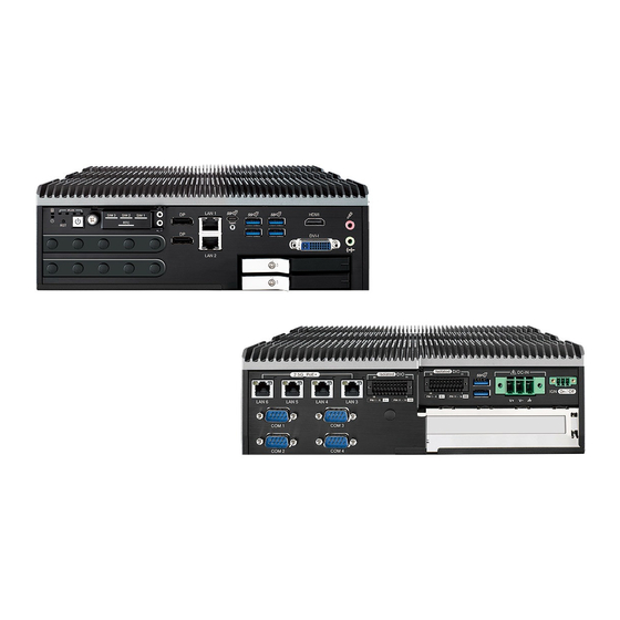
Front Panel I/O Functions
Rear Panel I/O & Functions
Main Board Expansion Connectors
Main Board Jumper Settings
Ignition Control
Chapter 3 System Setup
Installing CPU
Installing DDR5 SO-DIMM Modules
Installing Mini Pcie Card
Installing Nano SIM Card
Installing Removable RTC Battery
Installing Pcie Card
Installing SSD/HDD
Installing
Installing Antenna Cable
Mounting Your ECX-3200/3100
Chapter 4 Bios Setup
Entering BIOS Setup
Main Menu
Advanced Menu
Chipset Menu
Security Menu
Boot Menu
Save & Exit
APPENDIX A : Isolated DIO/GPIO Guide
APPENDIX B : Software Functions
APPENDIX C : RAID Functions
APPENDIX D : Power Consumption
APPENDIX E : Supported Memory & Storage List
Advertisement
Quick Links
Download this manual
ECX-3200/3100
13th/12th Gen Intel
Workstation-grade, 4 2.5G LAN w/4 X-coded M12 PoE+, 2 SSD Tray, 1 PCIe Slot
®
Core™ i9/i7/i5/i3 Expandable Fanless System
USER
USER
Manual
Manual
1.0.0 Edition 20230529
Table of
Contents
Previous
Page
Next
Page
1
2
3
4
5
Advertisement
Table of Contents
Need help?
Do you have a question about the ECX-3200 and is the answer not in the manual?
Ask a question
Questions and answers
Related Manuals for Vecow ECX-3200
Industrial PC Vecow ECS-4500 User Manual
Intel coretm i7/i5/i3 soc slim fanless embedded system (105 pages)
Industrial PC Vecow ECX-1210M User Manual
8th gen intel xeon/core i7/i5/i3 expandable fanless system workstation-grade, 6 gige lan w/4 m12 poe+, 2 ssd tray, pci/pcie slot (139 pages)
Industrial PC Vecow ECX-1000 series User Manual
8th gen intel xeon /core i7/i5/i3 fanless embedded system workstation-grade, 10gige lan, extended temperature (157 pages)
Industrial PC Vecow ECX-1400 Series User Manual
(146 pages)
Industrial PC Vecow ECX-1320 User Manual
(146 pages)
Industrial PC Vecow ECX-2000 Series User Manual
10th gen intel xeon/core i9/i7/i5/i3 fanless embedded system, workstation-grade, 2.5gige lan, 10gige lan, 9v to 50v dc-in (196 pages)
Industrial PC Vecow ECS-9771 User Manual
Intel xeon/core i7 4-port sfp+ 10 gige embedded system workstation-grade, high performance (104 pages)
Industrial PC Vecow ECX-2200A User Manual
(168 pages)
Industrial PC Vecow ECX-3100 User Manual
(147 pages)
Industrial PC Vecow ECX-3000 PEG User Manual
13th/12th gen intel core i9/i7/i5/i3 ai computing system workstation-grade, nvidia/amd graphics, 4 pcie (159 pages)
Industrial PC Vecow ECS-4700 User Manual
(107 pages)
Industrial PC Vecow EVS-2000 LIQ User Manual
10th gen. intel xeon/core i9/i7/i5/i3 fanless ai computing system (128 pages)
Industrial PC Vecow EAC-6000 User Manual
(59 pages)
Industrial PC Vecow EAC-6000-OOB User Manual
Nvidia jetson orin nx edge ai computing system allxon oob, 2 gige lan, 3 usb 3.1, -25 c to 70 c operation (66 pages)
Industrial PC Vecow MTC-8000 Series User Manual
(55 pages)
Industrial PC Vecow GPC-1000 Series User Manual
Intel xeon / core i7/i5/i3 dual gpu ai computing system workstation-grade, nvidia tesla /quadro / geforce graphics (92 pages)
This manual is also suitable for:
Ecx-3100
Ecx-3200mx
Table of Contents
Print
Rename the bookmark
Delete bookmark?
Delete from my manuals?
Login
Sign In
OR
Sign in with Facebook
Sign in with Google
Upload manual
Upload from disk
Upload from URL


Need help?
Do you have a question about the ECX-3200 and is the answer not in the manual?
Questions and answers