
Subscribe to Our Youtube Channel
Related Manuals for Vecow RES-1000 Series


Summary of Contents for Vecow RES-1000 Series
- Page 1 USER USER RES-1000 Manual Manual Intel ® Core™ i7/i5/i3 SoC IP67 Rugged Embedded System Multiple Waterproof M12 Connectors, Fanless -30°C to 70°C 1.0.0 Edition 20200103...
- Page 2 Record of Revision Version Date Page Description Remark 0.10 2019/12/30 Preliminary Release 1.00 2020/1/3 Official Release...
- Page 3 This manual is released by Vecow Co., Ltd. for reference purpose only. All product offerings and specifications are subject to change without prior notice. It does not represent commitment of Vecow Co., Ltd. Vecow shall not be liable for direct, indirect, special, incidental, or consequential damages arising out of the use of the product or documentation or any infringements upon the rights of third parties, which may result from such use.
- Page 4 Order Information Model Name Processor GigE LAN USB 2.0 ® RES-1000-600U Intel Core™ i7-6600U ® RES-1000-300U Intel Core™ i5-6300U ® RES-1000-100U Intel Core™ i3-6100U ® ® RES-1000-955U Intel Celeron 3955U Order Accessories Part Number Description DDR4 16G Certified DDR4 16GB 2133MHz RAM DDR4 8G Certified DDR4 8GB 2133MHz RAM DDR4 4G...
-
Page 5: Table Of Contents
Table of Contents CHAPTER 1 GENERAL INTRODUCTION 1.1 Overview 1.2 Features 1.3 Product Specification 1.4 Supported CPU List 1.5 Mechanical Dimensions CHAPTER 2 GETTING TO KNOW YOUR RES-1000 2.1 Packing List 2.2 Front Panel I/O Functions 2.3 Rear Panel I/O and Functions CHAPTER 3 SYSTEM SETUP 3.1 How to Use Your RES-1000 3.2 Mount Your RES-1000... - Page 6 APPENDIX A : Watchdog Function APPENDIX B : Software Functions APPENDIX C : RAID Functions APPENDIX D : Power Consumption...
-
Page 7: Chapter 1 General Introduction
12, OpenGL 4.5 and OpenCL 2.0 API; DVI-D display interface supports 1080p full HD resolution. Multiple Gen 3 PCIe (8GT/s), SATA III (6Gbps) and GigE (1Gbps) LAN make high-speed data conveying possible. Vecow RES-1000 Series Ultra-compact Fanless Embedded System delivers you outstanding Power-Efficient Performance for demanding workloads. -
Page 8: Features
IP67 Waterproof DVI-D Connector, up to 1920 x 1200 @60Hz Storage SATA 1 SATA III (6Gbps) mSATA 1 SATA III (Mini PCIe Type, 6Gbps) Storage Device • 1 mSATA Socket • 1 Internal 2.5" SSD/HDD Bracket (Optional) ©Vecow RES-1000 User Manual GENERAL INTRODUCTION... - Page 9 Ethernet ® LAN 1 Intel I219LM GigE LAN supports iAMT 11.0, X-coded M12 Connector ® LAN 2 Intel I210 GigE LAN, X-coded M12 Connector Power Power Input 9V to 36V, DC-in Power Interface A-coded M12 Connector Power Switch IP67 Waterproof Power Button Others Watchdog Timer Reset : 1 to 255 sec./min.
-
Page 10: Supported Cpu List
Up to 3.4 GHz i5-6300U Up to 3.0 GHz i3-6100U Up to 2.3 GHz Celeron 3955U Up to 2.0 GHz 1.5 Mechanical Dimensions Unit: mm (inch) 296.2 (11.66") 75.0 (2.95") 282.2 (11.11") 250.0 (9.84") A Detail ©Vecow RES-1000 User Manual GENERAL INTRODUCTION... -
Page 11: Chapter 2 Getting To Know Your Res-1000
GETTING TO KNOW YOUR RES-1000 2.1 Packing List Item Description RES-1000 Rugged Embedded System Driver/User Manual DVD Wall Mount Kit PHILLIPS F#6-32 screws for wall mount kit M12 to USB cable (2M Length) M12 to DC terminal block cable (2M Length) GETTING TO KNOW YOUR RES-1000... -
Page 12: Front Panel I/O Functions
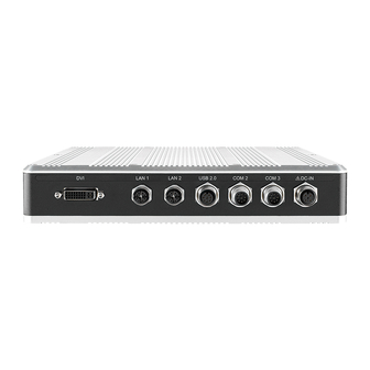
• Twinkling : Data transferring. 2.3 Rear Panel I/O and Functions In Vecow’s RES-1000, all I/O connectors are located on the Rear panel. Most of the general connections to the computer device, such as DVI-D, M12 jack for LAN,USB2.0,COM port and DC-IN , are placed on the Rear panel. - Page 13 2.3.1 DVI Connector LAN 1 LAN 2 USB 2.0 COM 2 COM 3 DC-IN The DVI connector on the rear panel supports only DVI-D display. This connector can either output DVI signal. The DVI output mode supports up to 1920 x 1200 resolution and output mode supports up to 1920 x 1200 resolution. The DVI is automatically selected according to the display device connected.
- Page 14 The default definition of COM 1 and COM 2 is RS-232, if you want to change to RS-422 or RS-485, you can find the setting in BIOS. The pin-outs of COM2 and COM3 are listed as follows: ©Vecow RES-1000 User Manual GETTING TO KNOW YOUR RES-1000...
- Page 15 Serial Pin No. RS-232 RS-422 RS-422 RS-485 Port (5-wire) (9-wire) (3-wire) TXD- TXD- DATA- TXD+ TXD+ DATA+ RXD+ RXD+ ----------- COM2 RXD- RXD- ----------- ----------- RTS- ----------- COM3 ----------- RTS+ ----------- ----------- CTS+ ----------- 2.3.5 DC JACK LAN 1 LAN 2 USB 2.0 COM 2 COM 3...
-
Page 16: Chapter 3 System Setup
SYSTEM SETUP 3.1 How to Use Your RES-1000 3.1.1 M12 A code/X code Step 1 Remove M12 cover. (Example DC-IN) Step 2 Confirm M12 connector pin defined. ©Vecow RES-1000 User Manual HARDWARE INSTALLATION... - Page 17 Step 3 Confirm wire. Step 4 Turn wire connector. Step 5 Locked. HARDWARE INSTALLATION...
- Page 18 3.1.2 DVI Step 1 Remove DVI cover. Step 2 Confirm DVI connector pin defined. Step 3 Confirm wire. ©Vecow RES-1000 User Manual HARDWARE INSTALLATION...
- Page 19 Step 4 Turn wire connector. Step 5 Locked. HARDWARE INSTALLATION...
-
Page 20: Mount Your Res-1000
3.2 Mount Your RES-1000 3.2.1 Wall Mount Step 1 Fasten four PHILLIPS #6-32 screws. 296.2 (11.66”) 282.2 (11.11”) 250.0 (9.84”) ©Vecow RES-1000 User Manual HARDWARE INSTALLATION... - Page 21 3.2.2 VESA Mount (75x75 mm) 75.0 (2.95”) HARDWARE INSTALLATION...
-
Page 22: Chapter 4 Bios Setup
BIOS provides an interface for users to check and change system configuration. The BIOS setup program is accessed by pressing the <Del> key when POST display output is shown. Figure 4-1 : Entering Setup Screen ©Vecow RES-1000 User Manual BIOS AND DRIVER SETTING... -
Page 23: Main Menu
4.2 Main Menu The main menu displays BIOS version and system information. There are two options on Main menu. Figure 4-2 : BIOS Main Menu System Date Set the Date. Use Tab to switch between Date elements. System Time Set the Time. Use Tab to switch between Time elements. BIOS AND DRIVER SETTING... -
Page 24: Advanced Function
Select the highest ACPI sleep state the system will enter when the SUSPEND button is pressed. S3 Video Repost Enable or disable S3 Video Repost. ACPI Low Power S0 Idle Enable or disable ACPI Low Power S0 Idle Support. ©Vecow RES-1000 User Manual BIOS AND DRIVER SETTING... - Page 25 4.3.2 AMT Configuration Figure 4-3-2 : Intel AMT Settings Intel AMT Enable/disable Intel Active Management Technology BIOS Extension. Note: iAMT H/W is always enabled. This option just controls the BIOS extension execution. If enabled, this requires additional firmware in the SPI device. 4.3.3 PCH-FW Configuration Figure 4-3-3 : PCH-FW Settings ME Unconfig on RTC Clear State...
- Page 26 Set parameters of serial port 3 (COM 3). Serial Port 4 Configuration Set parameters of serial port 4 (COM 4). Serial Port 5 Configuration Set parameters of serial port 5 (COM 5). ©Vecow RES-1000 User Manual BIOS AND DRIVER SETTING...
- Page 27 4.3.6 Hardware Monitor The IT8786 SIO features an enhanced hardware monitor providing thermal, fan speed, and system voltages' status monitoring. Figure 4-3-6 : Hardware Monitor Settings 4.3.7 Serial Port Console Redirection Figure 4-3-7 : Serial Port Console Redirection Settings Console Redirection Console redirection enable or disable.
- Page 28 Vanderpool Technology. Hardware Prefetcher To turn on/off the MLC streamer prefetcher. Adjacent Cache Line Prefetch To turn on/off prefetching of adjacent cache lines. CPU AES Enable/disabled CPU Advanced Encryption Standard instructions. ©Vecow RES-1000 User Manual BIOS AND DRIVER SETTING...
- Page 29 Boot performance mode Select the performance state that the BIOS will set before OS handoff. Intel SpeedStep Allows more than two frequency ranges to be supported. Turbo Mode Turbo Mode. CPU C state Enable or disable CPU C states. Enhanced C-states Enable/disabled C1E.
- Page 30 On an edge detect from 0 to 1, the PCH starts a COMRESET initialization sequence to the device. SATA Device Type Identify the SATA port is connected to Solid State Drive or Hard Disk Drive. ©Vecow RES-1000 User Manual BIOS AND DRIVER SETTING...
- Page 31 4.3.11 Acoustic Management Configuration Figure 4-3-11 : Acoustic Management Settings Acoustic Management Configuration Option to enable or disable Automatic Acoustic Management. 4.3.12 Network Stack Configuration Figure 4-3-12 : Network Stack Settings Network Stack Enable/disable UEFI Network Stack. Ipv4 PXE Support Enable Ipv4 PXE Boot Support.
- Page 32 IMMEDIATE - execute the trap right away; POSTPONED - execute the trap during legacy boot. Boot option filter This option controls Legacy/UEFI ROMs priority. Network Controls the execution of UEFI and Legacy PXE OpROM. ©Vecow RES-1000 User Manual BIOS AND DRIVER SETTING...
- Page 33 Storage Controls the execution of UEFI and Legacy Storage OpROM. Video Controls the execution of UEFI and Legacy Video OpROM. Other PCI devices Determines OpROM execution policy for devices other than network, storage, or video. 4.3.14 USB Configuration Figure 4-3-14 : USB Settings Network Stack Enable/disable UEFI Network Stack.
-
Page 34: Chipset
'Auto' uses default value: for a root port it is 100 ms, for a hub port the delay is taken from hub descriptor. 4.4 Chipset Figure 4-4 : BIOS Chipset Menu System Agent (SA) Configuration System Agent (SA) Parameters. PCH-IO Configuration PCH Parameters. LVDS Configuration LVDS Configuration. ©Vecow RES-1000 User Manual BIOS AND DRIVER SETTING... - Page 35 4.4.1 System Agent (SA) Configuration Figure 4-4-1 : USB Settings VT-d VT-d capability. GMM Device (B0:D8:F0) Enable/disable SA GMM Device. Above 4GB MMIO BIOS assignment Enable/disable above 4GB Memory MappedIO BIOS assignment. This is disabled automatically when Aperture Size is set to 2048MB. 4.4.2 Graphics Configuration of System Agent (SA) Figure 4-4-1 : USB Settings Graphics Turbo IMON Current...
- Page 36 Select DVMT5.0 Total Graphic Memory size used by the Internal Graphics Device. Cd Clock Frequency Select the highest Cd Clock frequency supported by the platform. 4.4.3 Memory Information of System Agent (SA) Figure 4-4-3 : Memory Information Display memory information. ©Vecow RES-1000 User Manual BIOS AND DRIVER SETTING...
- Page 37 4.4.4 PCH-IO Configuration Figure 4-4-4 : USB Settings PCH LAN Controller Enable or disable onboard NIC. Wake on LAN Enable or disable integrated LAN to wake the system. (The Wake On LAN cannot be disabled if ME is on at Sx state). Serial IRQ Mode Configure Serial IRQ Mode.
- Page 38 4.4.7 SB Porting Configuration of PCH-IO Figure 4-4-7 : RAID ROM Settings SATA RAID ROM Legacy ROM: Legacy option ROM UEFI Driver: UEFI Raid Driver Both: Run the legacy Option ROM and UEFI driver. ©Vecow RES-1000 User Manual BIOS AND DRIVER SETTING...
-
Page 39: Security
4.4.8 LVDS Configuration Figure 4-4-8 : LVDS Panel Settings LCD Panel Type Select LCD Panel Resolution. 4.5 Security Figure 4-5 : BIOS Security Menu Administrator Password Set Administrator Password. User Password Set User Password. BIOS AND DRIVER SETTING... -
Page 40: Boot
If the 'Set HDD User Password' option is grayed out, do power cycle to enable the option again. 4.6 Boot Figure 4-6 : BIOS Boot Menu ©Vecow RES-1000 User Manual BIOS AND DRIVER SETTING... -
Page 41: Save & Exit
Setup Prompt Timeout Number of seconds to wait for setup activation key. 65535(0xFFFF) means indefinite waiting. Bootup NumLock State Select the keyboard NumLock state. Quiet Boot Enables or disables Quiet Boot option. Boot Option #x Sets the system boot order. New Boot Option Policy Controls the placement of newly detected UEFI boot options. - Page 42 Restore/load default values for all the setup options. Save as User Defaults Save the changes done so far as User Defaults. Restore User Defaults Restore the User Defaults to all the setup options. ©Vecow RES-1000 User Manual BIOS AND DRIVER SETTING...
- Page 43 APPENDIX A : Watchdog Function A.1 Function Description The RES-1000 offers a watchdog timer. A.2 Software Package Contain Distribution folder include x32 and x64 versions, use batch file for installation. There are included as fallowed : Win7_32.bat : Installation for 32-bit driver Win7_64.bat : Windows update package which driver required (need to restart), and Installation for 64-bit driver...
- Page 44 WDT counting by program timer after set WDT. Shown after Write button action. WDT setup day format texts (user setting) : User setting, WDT value, format : day'hour'minute'second. WDT counting day format text (read only) : WDT counting, format : day'hour'minute'second. Appendix A ©Vecow RES-1000 User Manual...
- Page 45 TRUE (1) : Success; FALSE (0) : Fail (Initial error, or setup 0 error, or hardware problem) BOOL CancelWDT () Cancel watchdog timer Return : TRUE (1) : Success; FALSE (0) : Fail (Initial error, or hardware problem) ©Vecow User Manual Appendix B...
- Page 46 C.3 To Install All Device Drivers of the System The instructions are as follows : 1. To install Chipset driver 2. To install VGA driver 3. To install ME driver (if available) 4. To install Network driver 5. To install Audio driver Appendix C ©Vecow RES-1000 User Manual...
- Page 47 C.4 To Install "Intel Rapid Storage Technology" Software You can get the software from the driver CD. Also, you can find latest information and software directly from Intel website. http://www.intel.com/p/en_US/support/highlights/chpsts/imsm The RAID environment has been done if you completed the steps above. C.5 To Insert SATA HDD for RAID 1 Please notice, you can use three SATA ports for SATA storage devices.
- Page 48 Then add "Logical Device" for Windows access. C.8 If One SATA HDD on RAID Volume is Out-of-use After RAID 1 volume created, you can see the figure of SATA device allocation. HDD CAUTION Sign Appendix C ©Vecow RES-1000 User Manual...
- Page 49 C.9 Recovery and Auto Re-build When Use the SAME RAID HDD C.10 Recovery and Auto Re-build When Use DIFFERENT RAID HDD There is a warning will pop-up to ask you if the disk is not a member of original RAID volume. If you press "Rebuild", it will replace the broken SATA HDD to the last one SATA HDD of RAID volume.
- Page 50 USB Flash Transcend 3.0 8GB USB3.0 -4 USB Flash Transcend 3.0 8GB USB2.0-1 USB Flash ADATA 8GB USB2.0-2 Logitech M105 Mouse LAN1(I219) 1.0 Gbps LAN2(I210) 1.0 Gbps Graphics Output Power plan Balance(Windows8.1 Power Plan) Power Source Chroma 62006P-100-25 Appendix D ©Vecow RES-1000 User Manual...
- Page 51 0.338A 04.06W 0.894A 10.73W 1.712A 20.54W 3955U 0.296A 07.10W 0.570A 13.68W 0.976A 23.42W 3955U 0.291A 08.15W 0.532A 14.90W 0.843A 23.60W 3955U 0.274A 09.86W 0.456A 16.42W 0.734A 26.42W ** If more help is needed, please contact Vecow technical support. Appendix D...
- Page 52 No part of this publication may be reproduced in any form or by any means, electric, photocopying, or recording, without prior authorization from the publisher. The rights of all the brand names, product names, and trademarks belong to their respective owners. © Vecow Co., Ltd. 2020. All rights reserved.
Need help?
Do you have a question about the RES-1000 Series and is the answer not in the manual?
Questions and answers