
Subscribe to Our Youtube Channel
Related Manuals for Vecow ECX-1400 Series


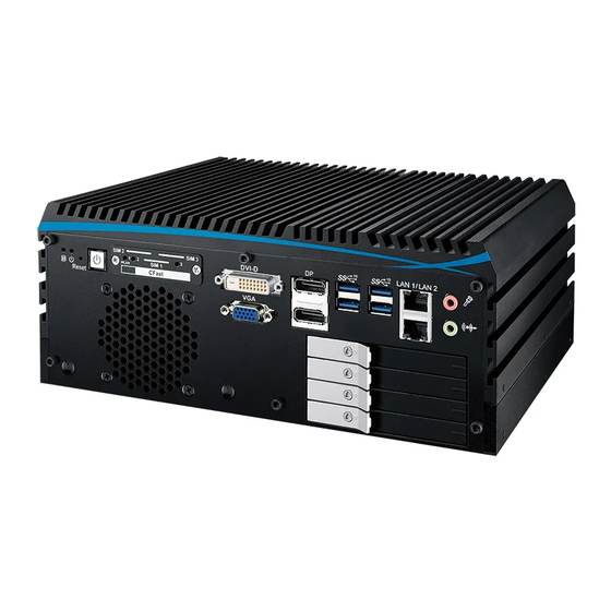
Summary of Contents for Vecow ECX-1400 Series
- Page 1 USER USER ECX-1400/1300 Manual Manual Gen Intel ® Xeon ® /Core™ i7/i5/i3 Expandable Fanless System Workstation-grade, 6 GigE LAN w/4 PoE , 4 SSD Tray, 2 PCI/PCIe Slot 1.0.0 Edition 20190402...
- Page 2 Record of Revision Version Date Page Description Remark 0.10 2019/01/09 Preliminary Release 1.00 2019/01/15 Official Release 1.10 2019/04/02 Update ©Vecow ECX-1400/1300 User Manual...
- Page 3 This manual is released by Vecow Co., Ltd. for reference purpose only. All product offerings and specifications are subject to change without prior notice. It does not represent commitment of Vecow Co., Ltd. Vecow shall not be liable for direct, indirect, special, incidental, or consequential damages arising out of the use of the product or documentation or any infringements upon the rights of third parties, which may result from such use.
- Page 4 1 PCIe x4, 2 SSD Tray, 6 USB 3.1, 4 COM, 3 SIM, 16 GPIO ® ® ECX-1300 with NVIDIA GeForce GTX 1050, 2 GigE LAN, ECX-1301 GTX1050 1 PCI, 2 SSD Tray, 6 USB 3.1, 4 COM, 3 SIM, 16 GPIO ©Vecow ECX-1400/1300 User Manual...
- Page 5 Terminal Block 20-pin to Terminal Block 20-pin Cable, 500cm Terminal Board with One 20-pin Terminal Block Connector and TMB-TMBK-20P DIN-Rail Mounting 4G Module Mini PCIe 4G/GPS Module with Antenna WiFi & Bluetooth WiFi & Bluetooth Module with Antenna ©Vecow ECX-1400/1300 User Manual...
-
Page 6: Table Of Contents
1.5.5 Dimensions of ECX-1311 1.5.6 Dimensions of ECX-1302 1.5.7 Dimensions of ECX-1400 GTX1070 1.5.8 Dimensions of ECX-1300 GTX1070 1.5.9 Dimensions of ECX-1410 GTX1050 1.5.10 Dimensions of ECX-1401 GTX1050 1.5.11 Dimensions of ECX-1310 GTX1050 1.5.12 Dimensions of ECX-1301 GTX1050 ©Vecow ECX-1400/1300 User Manual... - Page 7 3.8 Installing PCI/PCIe Card 3.9 Installing SSD/HDD 3.10 Installing M.2 3.11 Mounting Your ECX-1400/1300 CHAPTER 4 BIOS SETUP 4.1 Entering BIOS Setup 4.2 Main 4.3 Advanced 4.4 Chipset 4.5 Security 4.6 Boot 4.7 Save & Exit ©Vecow ECX-1400/1300 User Manual...
- Page 8 APPENDIX A : Isolated DIO Guide APPENDIX B : Software Functions APPENDIX C : RAID Functions APPENDIX D : Power Consumption APPENDIX E : Supported Memory & Storage List ©Vecow ECX-1400/1300 User Manual viii...
-
Page 9: Chapter 1 General Introduction
EN50155 and EN50121-3- 2 compliant, optional full function SUMIT A, B expansion supports multiple SIM sockets, 10GigE RJ45 or 10G SPF+ Fiber connections, Vecow ECX-1400/1300 Expandable Embedded Workstation serves compact integrated functions, flexible expansion features and optimized system operation for any embedded applications. -
Page 10: Features
HD displays (ECX-1400/1300 GTX1050) • 6V to 36V DC Power Input with 80V Surge Protection • 12V to 36V DC Power Input with 80V Surge Protection (ECX-1400/1300 GTX Series) • Configurable Ignition Power Control ©Vecow ECX-1400/1300 User Manual GENERAL INTRODUCTION... -
Page 11: Product Specification
• 4 Front-access 2.5" SSD/HDD Tray Audio Audio Codec Realtek ALC892, 5.1 Channel HD Audio Audio Interface 1 Mic-in, 1 Line-out Ethernet ® LAN 1 Intel I219LM GigE LAN supports iAMT 12.0 ® LAN 2 Intel I210 GigE LAN ©Vecow ECX-1400/1300 User Manual GENERAL INTRODUCTION... - Page 12 5% to 95% humidity, non-condensing Relative Humidity 95% at 75°C Shock • IEC 60068-2-27 • SSD : 50G @wallmount, Half-sine, 11ms Vibration • IEC 60068-2-64 • SSD : 5Grms, 5Hz to 500Hz, 3 Axis CE, FCC, EN50155, EN50121-3-2 ©Vecow ECX-1400/1300 User Manual GENERAL INTRODUCTION...
-
Page 13: Specifications Of Ecx-1411
• 4 Front-access 2.5" SSD/HDD Tray Audio Audio Codec Realtek ALC892, 5.1 Channel HD Audio Audio Interface 1 Mic-in, 1 Line-out Ethernet ® LAN 1 Intel I219LM GigE LAN supports iAMT 12.0 ® LAN 2 Intel I210 GigE LAN ©Vecow ECX-1400/1300 User Manual GENERAL INTRODUCTION... - Page 14 5% to 95% humidity, non-condensing Relative Humidity 95% at 75°C Shock • IEC 60068-2-27 • SSD : 50G @wallmount, Half-sine, 11ms Vibration • IEC 60068-2-64 • SSD : 5Grms, 5Hz to 500Hz, 3 Axis CE, FCC, EN50155, EN50121-3-2 ©Vecow ECX-1400/1300 User Manual GENERAL INTRODUCTION...
-
Page 15: Specifications Of Ecx-1402
• 4 Front-access 2.5" SSD/HDD Tray Audio Audio Codec Realtek ALC892, 5.1 Channel HD Audio Audio Interface 1 Mic-in, 1 Line-out Ethernet ® LAN 1 Intel I219LM GigE LAN supports iAMT 12.0 ® LAN 2 Intel I210 GigE LAN ©Vecow ECX-1400/1300 User Manual GENERAL INTRODUCTION... - Page 16 5% to 95% humidity, non-condensing Relative Humidity 95% at 75°C Shock • IEC 60068-2-27 • SSD : 50G @wallmount, Half-sine, 11ms Vibration • IEC 60068-2-64 • SSD : 5Grms, 5Hz to 500Hz, 3 Axis CE, FCC, EN50155, EN50121-3-2 ©Vecow ECX-1400/1300 User Manual GENERAL INTRODUCTION...
-
Page 17: Specifications Of Ecx-1320
• 4 Front-access 2.5" SSD/HDD Tray Audio Audio Codec Realtek ALC892, 5.1 Channel HD Audio Audio Interface 1 Mic-in, 1 Line-out Ethernet ® LAN 1 Intel I219LM GigE LAN supports iAMT 12.0 ® LAN 2 Intel I210 GigE LAN ©Vecow ECX-1400/1300 User Manual GENERAL INTRODUCTION... - Page 18 5% to 95% humidity, non-condensing Relative Humidity 95% at 75°C Shock • IEC 60068-2-27 • SSD : 50G @wallmount, Half-sine, 11ms Vibration • IEC 60068-2-64 • SSD : 5Grms, 5Hz to 500Hz, 3 Axis CE, FCC, EN50155, EN50121-3-2 ©Vecow ECX-1400/1300 User Manual GENERAL INTRODUCTION...
-
Page 19: Specifications Of Ecx-1311
• 4 Front-access 2.5" SSD/HDD Tray Audio Audio Codec Realtek ALC892, 5.1 Channel HD Audio Audio Interface 1 Mic-in, 1 Line-out Ethernet ® LAN 1 Intel I219LM GigE LAN supports iAMT 12.0 ® LAN 2 Intel I210 GigE LAN ©Vecow ECX-1400/1300 User Manual GENERAL INTRODUCTION... - Page 20 5% to 95% humidity, non-condensing Relative Humidity 95% at 75°C Shock • IEC 60068-2-27 • SSD : 50G @wallmount, Half-sine, 11ms Vibration • IEC 60068-2-64 • SSD : 5Grms, 5Hz to 500Hz, 3 Axis CE, FCC, EN50155, EN50121-3-2 ©Vecow ECX-1400/1300 User Manual GENERAL INTRODUCTION...
-
Page 21: Specifications Of Ecx-1302
• 4 Front-access 2.5" SSD/HDD Tray Audio Audio Codec Realtek ALC892, 5.1 Channel HD Audio Audio Interface 1 Mic-in, 1 Line-out Ethernet ® LAN 1 Intel I219LM GigE LAN supports iAMT 12.0 ® LAN 2 Intel I210 GigE LAN ©Vecow ECX-1400/1300 User Manual GENERAL INTRODUCTION... - Page 22 5% to 95% humidity, non-condensing Relative Humidity 95% at 75°C Shock • IEC 60068-2-27 • SSD : 50G @wallmount, Half-sine, 11ms Vibration • IEC 60068-2-64 • SSD : 5Grms, 5Hz to 500Hz, 3 Axis CE, FCC, EN50155, EN50121-3-2 ©Vecow ECX-1400/1300 User Manual GENERAL INTRODUCTION...
-
Page 23: Specifications Of Ecx-1400 Gtx1070
• 4 Front-access 2.5" SSD/HDD Tray Audio Audio Codec Realtek ALC892, 5.1 Channel HD Audio Audio Interface 1 Mic-in, 1 Line-out Ethernet ® LAN 1 Intel I219LM GigE LAN supports iAMT 12.0 ® LAN 2 Intel I210 GigE LAN ©Vecow ECX-1400/1300 User Manual GENERAL INTRODUCTION... - Page 24 5% to 95% humidity, non-condensing Relative Humidity 95% at 60°C Shock • IEC 60068-2-27 • SSD : 50G @wallmount, Half-sine, 11ms Vibration • IEC 60068-2-64 • SSD : 5Grms, 5Hz to 500Hz, 3 Axis CE, FCC, EN50155, EN50121-3-2 ©Vecow ECX-1400/1300 User Manual GENERAL INTRODUCTION...
-
Page 25: Specifications Of Ecx-1300 Gtx1070
• 4 Front-access 2.5" SSD/HDD Tray Audio Audio Codec Realtek ALC892, 5.1 Channel HD Audio Audio Interface 1 Mic-in, 1 Line-out Ethernet ® LAN 1 Intel I219LM GigE LAN supports iAMT 12.0 ® LAN 2 Intel I210 GigE LAN ©Vecow ECX-1400/1300 User Manual GENERAL INTRODUCTION... - Page 26 5% to 95% humidity, non-condensing Relative Humidity 95% at 60°C Shock • IEC 60068-2-27 • SSD : 50G @wallmount, Half-sine, 11ms Vibration • IEC 60068-2-64 • SSD : 5Grms, 5Hz to 500Hz, 3 Axis CE, FCC, EN50155, EN50121-3-2 ©Vecow ECX-1400/1300 User Manual GENERAL INTRODUCTION...
-
Page 27: Specifications Of Ecx-1410 Gtx1050
• 4 Front-access 2.5" SSD/HDD Tray Audio Audio Codec Realtek ALC892, 5.1 Channel HD Audio Audio Interface 1 Mic-in, 1 Line-out Ethernet ® LAN 1 Intel I219LM GigE LAN supports iAMT 12.0 ® LAN 2 Intel I210 GigE LAN ©Vecow ECX-1400/1300 User Manual GENERAL INTRODUCTION... - Page 28 5% to 95% humidity, non-condensing Relative Humidity 95% at 60°C Shock • IEC 60068-2-27 • SSD : 50G @wallmount, Half-sine, 11ms Vibration • IEC 60068-2-64 • SSD : 5Grms, 5Hz to 500Hz, 3 Axis CE, FCC, EN50155, EN50121-3-2 ©Vecow ECX-1400/1300 User Manual GENERAL INTRODUCTION...
-
Page 29: Specifications Of Ecx-1401 Gtx1050
• 4 Front-access 2.5" SSD/HDD Tray Audio Audio Codec Realtek ALC892, 5.1 Channel HD Audio Audio Interface 1 Mic-in, 1 Line-out Ethernet ® LAN 1 Intel I219LM GigE LAN supports iAMT 12.0 ® LAN 2 Intel I210 GigE LAN ©Vecow ECX-1400/1300 User Manual GENERAL INTRODUCTION... - Page 30 5% to 95% humidity, non-condensing Relative Humidity 95% at 60°C Shock • IEC 60068-2-27 • SSD : 50G @wallmount, Half-sine, 11ms Vibration • IEC 60068-2-64 • SSD : 5Grms, 5Hz to 500Hz, 3 Axis CE, FCC, EN50155, EN50121-3-2 ©Vecow ECX-1400/1300 User Manual GENERAL INTRODUCTION...
-
Page 31: Specifications Of Ecx-1310 Gtx1050
• 4 Front-access 2.5" SSD/HDD Tray Audio Audio Codec Realtek ALC892, 5.1 Channel HD Audio Audio Interface 1 Mic-in, 1 Line-out Ethernet ® LAN 1 Intel I219LM GigE LAN supports iAMT 12.0 ® LAN 2 Intel I210 GigE LAN ©Vecow ECX-1400/1300 User Manual GENERAL INTRODUCTION... - Page 32 5% to 95% humidity, non-condensing Relative Humidity 95% at 60°C Shock • IEC 60068-2-27 • SSD : 50G @wallmount, Half-sine, 11ms Vibration • IEC 60068-2-64 • SSD : 5Grms, 5Hz to 500Hz, 3 Axis CE, FCC, EN50155, EN50121-3-2 ©Vecow ECX-1400/1300 User Manual GENERAL INTRODUCTION...
-
Page 33: Specifications Of Ecx-1301 Gtx1050
• 4 Front-access 2.5" SSD/HDD Tray Audio Audio Codec Realtek ALC892, 5.1 Channel HD Audio Audio Interface 1 Mic-in, 1 Line-out Ethernet ® LAN 1 Intel I219LM GigE LAN supports iAMT 12.0 ® LAN 2 Intel I210 GigE LAN ©Vecow ECX-1400/1300 User Manual GENERAL INTRODUCTION... - Page 34 5% to 95% humidity, non-condensing Relative Humidity 95% at 60°C Shock • IEC 60068-2-27 • SSD : 50G @wallmount, Half-sine, 11ms Vibration • IEC 60068-2-64 • SSD : 5Grms, 5Hz to 500Hz, 3 Axis CE, FCC, EN50155, EN50121-3-2 ©Vecow ECX-1400/1300 User Manual GENERAL INTRODUCTION...
-
Page 35: Supported Cpu List
Up to 3.1GHz 1.5 Mechanical Dimension 1.5.1 Dimensions of ECX-1420 297.0 (11.69”) Unit : mm (inch) 282.0 (11.10”) 260.0 (10.24”) 5.0 (0.20”) A Detail 260.0 (10.24”) 13.0 (0.51”) 107.5 (4.23”) 94.5 (3.72”) 215.0 (8.46”) ©Vecow ECX-1400/1300 User Manual GENERAL INTRODUCTION... -
Page 36: Dimensions Of Ecx-1411
107.5 (4.23”) 94.5 (3.72”) 215.0 (8.46”) 1.5.3 Dimensions of ECX-1402 297.0 (11.69”) Unit : mm (inch) 282.0 (11.10”) 260.0 (10.24”) 5.0 (0.20”) A Detail 260.0 (10.24”) 13.0 (0.51”) 107.5 (4.23”) 94.5 (3.72”) 215.0 (8.46”) ©Vecow ECX-1400/1300 User Manual GENERAL INTRODUCTION... -
Page 37: Dimensions Of Ecx-1320
107.5 (4.23”) 94.5 (3.72”) 215.0 (8.46”) 1.5.5 Dimensions of ECX-1311 297.0 (11.69”) Unit : mm (inch) 282.0 (11.10”) 260.0 (10.24”) 5.0 (0.20”) A Detail 260.0 (10.24”) 13.0 (0.51”) 107.5 (4.23”) 94.5 (3.72”) 215.0 (8.46”) ©Vecow ECX-1400/1300 User Manual GENERAL INTRODUCTION... -
Page 38: Dimensions Of Ecx-1302
107.5 (4.23”) 94.5 (3.72”) 215.0 (8.46”) 1.5.7 Dimensions of ECX-1400 GTX1070 297.0 (11.69”) Unit : mm (inch) 282.0 (11.10”) 260.0 (10.24”) 5.0 (0.20”) A Detail 260.0 (10.24”) 13.0 (0.51”) 107.5 (4.23”) 94.5 (3.72”) 215.0 (8.46”) ©Vecow ECX-1400/1300 User Manual GENERAL INTRODUCTION... -
Page 39: Dimensions Of Ecx-1300 Gtx1070
107.5 (4.23”) 94.5 (3.72”) 215.0 (8.46”) 1.5.9 Dimensions of ECX-1410 GTX1050 297.0 (11.69”) Unit : mm (inch) 282.0 (11.10”) 260.0 (10.24”) 5.0 (0.20”) A Detail 260.0 (10.24”) 13.0 (0.51”) 107.5 (4.23”) 94.5 (3.72”) 215.0 (8.46”) ©Vecow ECX-1400/1300 User Manual GENERAL INTRODUCTION... -
Page 40: Dimensions Of Ecx-1401 Gtx1050
107.5 (4.23”) 94.5 (3.72”) 215.0 (8.46”) 1.5.11 Dimensions of ECX-1310 GTX1050 297.0 (11.69”) Unit : mm (inch) 282.0 (11.10”) 260.0 (10.24”) 5.0 (0.20”) A Detail 260.0 (10.24”) 13.0 (0.51”) 107.5 (4.23”) 94.5 (3.72”) 215.0 (8.46”) ©Vecow ECX-1400/1300 User Manual GENERAL INTRODUCTION... -
Page 41: Dimensions Of Ecx-1301 Gtx1050
1.5.12 Dimensions of ECX-1301 GTX1050 297.0 (11.69”) Unit : mm (inch) 282.0 (11.10”) 260.0 (10.24”) 5.0 (0.20”) A Detail 260.0 (10.24”) 13.0 (0.51”) 107.5 (4.23”) 94.5 (3.72”) 215.0 (8.46”) ©Vecow ECX-1400/1300 User Manual GENERAL INTRODUCTION... -
Page 42: Chapter 2 Getting To Know Your Ecx-1400/1300
Item Description ECX-1400 Expandable Fanless Embedded System (According to the configuration of you order, the ECX-1400 series may contain SSD/ HDD and DDR4 SO-DIMM. Please verify these items if necessary.) ECX-1400 series accessory box, which contains • ecow Drivers & Utilities DVD... - Page 43 ECX-1300 Expandable Fanless Embedded System (According to the configuration of you order, the ECX-1300 series may contain SSD/ HDD and DDR4 SO-DIMM. Please verify these items if necessary.) ECX-1300 series accessory box, which contains • Vecow Drivers & Utilities DVD Item Description Outlook...
-
Page 44: Front Panel I/O Functions
2.2 Front Panel I/O Functions In Vecow ECX-1300/1400 series family, all I/O connectors are located on front panel and rear panel. Most of the general connections to computer device, such as USB, LAN Jack, Display, DVI-D, VGA, Display Port and any additional storage, are placed on the front panel. - Page 45 The pinouts of CFast port are listed as follows : Pin No. Description Pin No. Description SATA_TXP6 SATA_TXN6 CFAST_LED SATA_RXN6 PC10 SATA_RXP6 PC11 PC12 PC13 +3.3V PC14 +3.3V PC15 PC16 PC17 ©Vecow ECX-1400/1300 User Manual GETTING TO KNOW YOUR ECX-1400/1300...
- Page 46 1920 x 1200 resolution. The DVI is automatically selected according to the display device connected. You will need a DVI-D cable when connecting to a display device. ©Vecow ECX-1400/1300 User Manual GETTING TO KNOW YOUR ECX-1400/1300...
- Page 47 DVI-D LAN 1 / LAN 2 SIM 1 WLAN CFast ANT 3 ANT 4 Onboard Display Port support auxiliary channel dual mode, connection supports up to 4096x2304 resolution at 60 Hz. ©Vecow ECX-1400/1300 User Manual GETTING TO KNOW YOUR ECX-1400/1300...
- Page 48 Mini PCIe Slot/SIM Slot/WLAN LED Mapping Table : Mini PCIe SIM 2 SIM 3 MPCIe 1 SIM 1 (CN19) MPCIe 2 SIM 2 (CN20) SIM 1 M.2 KEY B SIM 3 (CN21) Mini-PCIe2 M.2 Key B Mini-PCIe1 CN19 ©Vecow ECX-1400/1300 User Manual GETTING TO KNOW YOUR ECX-1400/1300...
- Page 49 The pin-outs of LAN 1 and LAN 2 are listed as follows : Pin No. 10/100 Mbps 1000Mbps E_TX+ MDI0_P E_TX- MDI0_N E_RX+ MDI1_P ----- MDI2_P ----- MDI2_N E_RX- MDI1_N ----- MDI3_P ----- MDI3_N ©Vecow ECX-1400/1300 User Manual GETTING TO KNOW YOUR ECX-1400/1300...
- Page 50 ANT 3 ANT 4 There are 4 front-access 2.5" SSD/HDD trays in the front side of ECX- 1300/1400 series. Just trigger to open the SSD/HDD tray, up to 4TB is available. ©Vecow ECX-1400/1300 User Manual GETTING TO KNOW YOUR ECX-1400/1300...
-
Page 51: Rear Panel I/O & Functions
You could turn on or off the system power by using this contact. This terminal block supports dual function of soft power-on/power-off (instant off or delay 4 second), and suspend mode. Pin No. Definition Pin No. Definition Ignition ©Vecow ECX-1400/1300 User Manual GETTING TO KNOW YOUR ECX-1400/1300... - Page 52 2.3.3 Isolated DIO/GPIO 2.3.3.1 Isolated DIO ECX-1400 series : DIO 2 DIO 1 DC-IN 6-36V On | Off Isolated Isolated LAN6 LAN5 LAN4 LAN3 PIN 1 ~ 8 PIN 11 ~ 18 PIN 1 ~ 8 PIN 11 ~ 18...
- Page 53 DIO2_GND DIO 2 OUTPUT 0 SIO_GPO22 OUTPUT 1 SIO_GPO26 OUTPUT 2 SIO_GPO64 OUTPUT 3 SIO_GPO65 OUTPUT 4 SIO_GPO41 OUTPUT 5 SIO_GPO40 OUTPUT 6 SIO_GPO52 OUTPUT 7 SIO_GPO27 DIO2_GND DIO2_VDC (6~48V Input) ©Vecow ECX-1400/1300 User Manual GETTING TO KNOW YOUR ECX-1400/1300...
- Page 54 DO (Pin 11-18) DIO_GND (Pin 10, 19) 2.3.3.2 GPIO ECX-1300 series : DIO 1 DC-IN 6-36V On | Off ANT 1 COM 1 COM 2 COM 3 COM 4 ANT 2 ©Vecow ECX-1400/1300 User Manual GETTING TO KNOW YOUR ECX-1400/1300...
- Page 55 COM 2 is RS-232, if you want to change to RS-422 or RS-485, you can find the setting in BIOS. BIOS Setting Function RS-232 COM 1 RS-422 (5-wire) COM 2 RS-422 (9-wire) COM 3 RS-485 COM 4 RS-485 w/z auto-flow control ©Vecow ECX-1400/1300 User Manual GETTING TO KNOW YOUR ECX-1400/1300...
- Page 56 COM Port MB Connector COM Port MB Connector COM 1 CN13 COM 2 CN14 COM 3 CN15 COM 4 CN16 Pin No. Signal Name CN13 to CN16 CN16 CN15 CN14 CN13 ©Vecow ECX-1400/1300 User Manual GETTING TO KNOW YOUR ECX-1400/1300...
- Page 57 2.3.5 PoE Ports ECX-1400 series : DIO 2 DIO 1 DC-IN 6-36V On | Off LAN6 LAN5 LAN4 LAN3 Isolated Isolated PIN 1 ~ 8 PIN 11 ~ 18 PIN 1 ~ 8 PIN 11 ~ 18 ANT 1 COM 1...
- Page 58 LAN5 LAN4 LAN3 PIN 1 ~ 8 PIN 11 ~ 18 PIN 1 ~ 8 PIN 11 ~ 18 ANT 1 COM 1 COM 2 COM 3 COM 4 ANT 2 ©Vecow ECX-1400/1300 User Manual GETTING TO KNOW YOUR ECX-1400/1300...
- Page 59 ANT 2 ECX-1300 GTX1070 : DIO 1 DC-IN 6-36V On | Off ANT 1 COM 1 COM 2 COM 3 COM 4 ANT 2 ECX-1300/1400 with GTX1070 support GTX1070 graphic card only. ©Vecow ECX-1400/1300 User Manual GETTING TO KNOW YOUR ECX-1400/1300...
-
Page 60: Main Board Expansion Connectors
2.4.1 Top View (Component Side) of ECX-1300/1400 Main Board With Connector Location CPU_FAN1 CN16 CN15 CN31 CN14 CN13 CN17 SODIMM_2 CN18 SATA2 SATA1 SODIMM_1 SATA4 SATA3 MPCIE2 M2_CN3 M2_CN2 M2_CN1 MPCIE1 ©Vecow ECX-1400/1300 User Manual GETTING TO KNOW YOUR ECX-1400/1300... - Page 61 2.4.2 Bottom View (Solder Side) of ECX-1300/1400 Main Board With Connector Location CN20 CN21 ©Vecow ECX-1400/1300 User Manual GETTING TO KNOW YOUR ECX-1400/1300...
- Page 62 1300/1400. It supports higher storage capacity with less cabling effort and smaller required space. The pin assignments of SATA1 and SATA2, SATA3, SATA4 are listed in the following table : SATA2 SATA1 SATA4 SATA3 Pin No. Definition Pin No. Definition ©Vecow ECX-1400/1300 User Manual GETTING TO KNOW YOUR ECX-1400/1300...
- Page 63 It also compliant with the requirements of SuperSpeed (SS), high speed (HS), full speed (FS) and low speed (LS). The pin assignments of J7are listed in the following table : Pin No. Description Pin No. Description USB_VCC USBD+ USBD- ©Vecow ECX-1400/1300 User Manual GETTING TO KNOW YOUR ECX-1400/1300...
- Page 64 SODIMM_2 SODIMM_1 Slot Description SODIMM_1 DDR4 Channel A SODIMM_2 DDR4 Channel B 2.4.8 CN1 : BIOS Socket If the BIOS needs to be changed, please contact the Vecow RMA service team. ©Vecow ECX-1400/1300 User Manual GETTING TO KNOW YOUR ECX-1400/1300...
- Page 65 Pin No. Description Pin No. Description +VDC_IN +VDC_IN (6~36V, Max.9A) (6~36V, Max.9A) +VDC_IN Ground (6~36V, Max.9A) Ground Ground 2.4.10 Mini PCIe : MPCIe_1, MPCIe_2 Standard full length mini PCIe slot MPCIE2 MPCIE1 ©Vecow ECX-1400/1300 User Manual GETTING TO KNOW YOUR ECX-1400/1300...
- Page 66 Reserved +3.3Vaux USB_D+ USB_D- PETp0 PETn0 SMB_DATA SMB_CLK +1.5V PERp0 PERn0 +3.3Vaux PERST# Reserved reserved Reserved Mechanical Key UIM_VPP REFCLK+ UIM_RESET REFCLK- UIM_CLK UIM_DATA CLKREQ# UIM_PWR Reserved 1.5V Reserved WAKE# 3.3Vaux ©Vecow ECX-1400/1300 User Manual GETTING TO KNOW YOUR ECX-1400/1300...
- Page 67 The system's real-time clock is powered by a lithium battery. It is Equipped with Panasonic BR2032 190mAh lithium battery. It is recommended that you not replace the lithium battery on your own. If the battery needs to be changed, please contact the Vecow RMA service team. BAT1 2.4.12 CPU_FAN1 : FAN Header Fan power connector supports for additional thermal requirements.
- Page 68 Ground LAD1 CLOCK LAD2 Ground 2.4.14 M2_CN1, M2_CN3 : M.2 slot 2280 length and 2230 length M.2 slot The pin assignments of M2_CN1, M2_CN3 in the following table : M2_CN3 M2_CN1 ©Vecow ECX-1400/1300 User Manual GETTING TO KNOW YOUR ECX-1400/1300...
- Page 69 REFCLKp REFCLKn PEWAKE# Ground CLKREQ# PETn0/SATA-A+ PERST# PETn0/SATA-A- Ground PERn0/SATA-B- PERn0/SATA-B+ Ground DEVSLP UIM-PWR Ground UIM-DATA UIM-CLK UIM-RESET Ground Mechanical Key Ground USB- LED_1# USB+ W_DISABLE1 FULL_CARD_PWR_OFF/ Ground Ground 3.3V 3.3V ©Vecow ECX-1400/1300 User Manual GETTING TO KNOW YOUR ECX-1400/1300...
- Page 70 Ground ALERT I2C_CLK Ground I2C_DATA PEWAKE0# CLKREQ0# Ground PERST0# REFCLKn0 REFCLKp0 Ground PERn0 PERp0 Ground PETn0 DEVSLP PETp0 Ground Mechanical Key Ground Ground Ground Ground USB- LED1# USB+ 3.3V Ground 3.3V ©Vecow ECX-1400/1300 User Manual GETTING TO KNOW YOUR ECX-1400/1300...
-
Page 71: Main Board Jumper Settings
You may configure your card to match the needs of your application by DIP switch. As below show the deep switch on and off. 1 : OFF 1 : ON 1 : ON 2 : OFF 2 : OFF 2 : ON ©Vecow ECX-1400/1300 User Manual GETTING TO KNOW YOUR ECX-1400/1300... - Page 72 LAN5 LAN4 LAN3 PIN 1 ~ 8 PIN 11 ~ 18 PIN 1 ~ 8 PIN 11 ~ 18 ANT 1 COM 1 COM 2 COM 3 COM 4 ANT 2 ©Vecow ECX-1400/1300 User Manual GETTING TO KNOW YOUR ECX-1400/1300...
- Page 73 3 - 4 +12V (0.5A max.) 5 - 6 RI (Default) COM3 to COM4 7 - 8 +5V (1A max.) 9 - 10 +12V (0.5A max.) 11 - 12 RI (Default) ©Vecow ECX-1400/1300 User Manual GETTING TO KNOW YOUR ECX-1400/1300...
- Page 74 PoE power on after system power on (Default) No Jumper Disable PoE power 2.5.5 JCMOS1 : CMOS JCMOS1 Jumper Setting Function JCMOS1 1 : 2 *Normal (Default) JCMOS1 2 : 3 Clear CMOS ©Vecow ECX-1400/1300 User Manual GETTING TO KNOW YOUR ECX-1400/1300...
-
Page 75: Ignition Control
2.6.1 Adjust Ignition Control Modes ECX-1300/1400 series provides 16 modes of different power on/off delay periods adjustable via SW2 switch. The default rotary switch is set to 0 in ATX/ AT power mode. ©Vecow ECX-1400/1300 User Manual GETTING TO KNOW YOUR ECX-1400/1300... - Page 76 5 seconds 30 minutes 5 seconds 1 hour 10 seconds 2 hours 10 seconds 4 hours 10 seconds 6 hours 10 seconds 8 hours 10 seconds 12 hours 10 seconds 24 hours ©Vecow ECX-1400/1300 User Manual GETTING TO KNOW YOUR ECX-1400/1300...
- Page 77 3. For proper ignition control, the power button setting should be "Power Down" mode. In Windows for example, you need to set "When I press the power button" to Shut down. ©Vecow ECX-1400/1300 User Manual GETTING TO KNOW YOUR ECX-1400/1300...
-
Page 78: Chapter 3 System Setup
SYSTEM SETUP 3.1 How to Open Your ECX-1400/1300 Step 1 Remove six PHILLIPS#6-32 screws. Step 2 Take off the PCI/PCIe tray. ©Vecow ECX-1400/1300 User Manual SYSTEM SETUP... - Page 79 Step 3 Remove two PHILLIPS#6-32 screws. Step 4 Turn over ECX-1300/1400 to face the front side. ©Vecow ECX-1400/1300 User Manual SYSTEM SETUP...
- Page 80 Step 5 Remove one HEX#6-32 screw. Step 6 Take out SSD/HDD tray module. ©Vecow ECX-1400/1300 User Manual SYSTEM SETUP...
-
Page 81: Installing Cpu
Step 7 Finish. 3.2 Installing CPU Step 1 Remove SATA DATA, SATA Power and COM cable. ©Vecow ECX-1400/1300 User Manual SYSTEM SETUP... - Page 82 Step 2 Remove FAN cable. (ECX-1400/1300 GTX series) Step 3 Remove five HEX#6-32 and four HEX#4-40 screws. ©Vecow ECX-1400/1300 User Manual SYSTEM SETUP...
- Page 83 Step 4 Remove front panel and turn over to face the rear side. Step 5 Remove four HEX#6-32 screws. Step 6 Remove four HEX#6-32 screws. ©Vecow ECX-1400/1300 User Manual SYSTEM SETUP...
- Page 84 Step 7 Remove twelve PHILLIPS M3 screws and take out main board from the heat sink. Step 8 Turn over the main board to make the CPU socket side up. ©Vecow ECX-1400/1300 User Manual SYSTEM SETUP...
- Page 85 Step 9 Unlock the CPU socket. Step 10 Open the CPU socket cover. ©Vecow ECX-1400/1300 User Manual SYSTEM SETUP...
- Page 86 Step 11 Watch out the direction of CPU and put CPU into the CPU socket. Step 12 Remove the mylar from CPU cover and lock the cover. ©Vecow ECX-1400/1300 User Manual SYSTEM SETUP...
- Page 87 Step 13 Cover and lock the CPU socket. ©Vecow ECX-1400/1300 User Manual SYSTEM SETUP...
-
Page 88: Installing Ddr4 So-Dimm Modules
3.3 Installing DDR4 SO-DIMM Modules Step 1 DDR4 SO-DIMM socket. Step 2 Install DDR4 RAM module Step 3 Install DDR4 RAM module into SO-DIMM socket and into SO-DIMM socket and locked. locked. ©Vecow ECX-1400/1300 User Manual SYSTEM SETUP... -
Page 89: Installing Mini Pcie Card
3.4 Installing Mini PCIe Card Step 1 Mini PCIe socket. Step 2 Install Mini PCIe card into Step 3 Fasten PHILLIPS M2.5 socket. screw. ©Vecow ECX-1400/1300 User Manual SYSTEM SETUP... -
Page 90: Installing Antenna Cable
3.5 Installing Antenna Cable Step 1 Check Antenna cable and washer. Step 2 Fasten washer 1 and 2. Step 3 Finished. ©Vecow ECX-1400/1300 User Manual SYSTEM SETUP... -
Page 91: Installing Cfast Card
Step 2 Remove CFast & SIM Card cover. Step 3 Before Inserting CFast & SIM Card, make sure the system power is not plugged. Step 4 Insert CFast card and push to lock. ©Vecow ECX-1400/1300 User Manual SYSTEM SETUP... -
Page 92: Installing Sim Card
Step 2 Remove CFast & SIM Card cover. Step 3 Before Inserting CFast & SIM Card, make sure the system power is not plugged. Step 4 Insert SIM card and push to lock. ©Vecow ECX-1400/1300 User Manual SYSTEM SETUP... -
Page 93: Installing Pci/Pcie Card
3.8 Installing PCI/PCIe Card Step 1 Remove PCI bracket and PHILLIPS#6-32 screw. Step 2 Match the PCI/PCIe card and the tray. ©Vecow ECX-1400/1300 User Manual SYSTEM SETUP... - Page 94 Step 3 Fasten PHILLIPS#6-32 screw. ©Vecow ECX-1400/1300 User Manual SYSTEM SETUP...
-
Page 95: Installing Ssd/Hdd
3.9 Installing SSD/HDD Step 1 Unlock SSD/HDD tray. Step 2 Pull the trigger and open SSD/HDD tray. ©Vecow ECX-1400/1300 User Manual SYSTEM SETUP... - Page 96 Step 3 Install 2.5" SSD/HDD into the tray and then push back to close the tray. Step 4 Lock the SSD/HDD tray with key. ©Vecow ECX-1400/1300 User Manual SYSTEM SETUP...
-
Page 97: Installing
3.10 Installing M.2 Step 1 M.2 socket. Step 2 Install M.2 into socket and fasten 1pcs PHILLIPS M3 screw. ©Vecow ECX-1400/1300 User Manual SYSTEM SETUP... -
Page 98: Mounting Your Ecx-1400/1300
3.11 Mounting Your ECX-1400/1300 3.11.1 Wall mount Fasten six PHILLIPS#10-32 screws. 260.0 (10.24”) 3.11.2 VESA mount Fasten six PHILLIPS#10-32 screws. VESA 75 x 75/100 x 100 mm 100.0 (3.94”) 75.0 (2.95”) 260.0 (10.24”) ©Vecow ECX-1400/1300 User Manual SYSTEM SETUP... - Page 99 3.11.3 Din Rail Kit Fasten six PHILLIPS#10-32 screws. 260.0 (10.24”) ©Vecow ECX-1400/1300 User Manual SYSTEM SETUP...
-
Page 100: Chapter 4 Bios Setup
Figure 4-1 : Entering Setup Screen BIOS provides an interface for users to check and change system configuration. The BIOS setup program is accessed by pressing the <Del> key when POST display output is shown. ©Vecow ECX-1400/1300 User Manual BIOS SETUP... -
Page 101: Main
Set the time. Use <Tab> to switch between time elements. 4.3 Advanced Figure 4-3 : BIOS Advanced Menu Select advanced tab to enter advanced BIOS setup options, such as CPU configuration, SATA configuration, and USB configuration. ©Vecow ECX-1400/1300 User Manual BIOS SETUP... - Page 102 Technology). When disabled only one thread per core is enabled. Enable/disable CPU Advanced Encryption Standard instructions. Intel Trusted Execution Technology Enables utilization of additional hardware capabilities provided by Intel Trusted Execution Technology. Changes require a full power cycle to take effect. ©Vecow ECX-1400/1300 User Manual BIOS SETUP...
- Page 103 CPPCv2 interface to allow for hardware controlled P-states. Turbo Mode Turbo Mode. C states Enable or disable CPU C states. Enhanced C-states Enable/disable C1E. When enabled, CPU will switch to minimum speed when all cores enter C-State. ©Vecow ECX-1400/1300 User Manual BIOS SETUP...
- Page 104 When disabled AMT BIOS Features are no longer supported and user is no longer able to access MEBx Setup. AMT Configuration ® Configure Intel Active Management Technology Parameters. ME Unconfig on RTC Clear State Disabling this option will cause ME not to unconfigure on RTC clear. ©Vecow ECX-1400/1300 User Manual BIOS SETUP...
- Page 105 Enables or disables S3 video repost. 4.3.6 SMART Settings Figure 4-3-6 : SMART Settings SMART Self Test Run SMART self test on all HDDs during POST. 4.3.7 IT8786 Super IO Configuration Figure 4-3-7 : IT8786 Super IO Settings ©Vecow ECX-1400/1300 User Manual BIOS SETUP...
- Page 106 Temperature Limit value of Fan Start (Degree C). (Range : 10~80) PWM Start Value (%) Default PWM Value of Fan. (Range : 15%~100%) Full Speed Temperature Temperature Limit value of Fan Full Speed (Degree C). (Range : 50~90) ©Vecow ECX-1400/1300 User Manual BIOS SETUP...
- Page 107 Legacy Console Redirection Legacy Console Redirection Settings. Serial Port for Out-of-Band Management/Windows Emergency Management Services (EMS) Console redirection enable or disable. 4.3.10 Intel TXT Information Figure 4-3-10 : Intel TXT Information Display Intel TXT information. ©Vecow ECX-1400/1300 User Manual BIOS SETUP...
- Page 108 Globally Enables or Disables Hot-Plug support for the entire System. If system has Hot-Plug Capable Slots and this option set to Enabled, it provides a Setup screen for selecting PCI resource padding for Hot-Plug. ©Vecow ECX-1400/1300 User Manual BIOS SETUP...
- Page 109 IP6 Configuration Policy Set IP6 Configuration Policy. PXE boot wait time Wait time to press ESC key to abort the PXE boot. Media detect count Number of times presence of media will be checked. ©Vecow ECX-1400/1300 User Manual BIOS SETUP...
- Page 110 Controls the execution of UEFI and Legacy Storage OpROM. Video Allows more than two frequency ranges to be supported. Other PCI devices Determines OpROM execution policy for devices other than network, storage, or video. ©Vecow ECX-1400/1300 User Manual BIOS SETUP...
- Page 111 Maximum time the device will take before it properly reports itself to the Host Controller. 'Auto' uses default value, for a root port it is 100 ms, for a hub port the delay is taken from the hub descriptor. ©Vecow ECX-1400/1300 User Manual BIOS SETUP...
-
Page 112: Chipset
VT-d capability. Above 4GB MMIO BIOS assignment Enable/disable above 4GB MemoryMappedIO BIOS assignment. This is disabled automatically when aperture size is set to 2048MB. 4.4.1.1 Memory Configuration Figure 4-4-1-1 : Memory Information Displays memory information. ©Vecow ECX-1400/1300 User Manual BIOS SETUP... - Page 113 2048MB aperture. To use this feature, please disable CSM Support. DVMT Pre-Allocated Select DVMT 5.0 Pre-Allocated (Fixed) Graphics Memory size used by the Internal Graphics Device. DVMT Total Gfx Mem Select DVMT5.0 Total Graphic Memory size used by the Internal Graphics Device. ©Vecow ECX-1400/1300 User Manual BIOS SETUP...
- Page 114 Specify what state to go to when power is re-applied after a power failure (G3 state). S0 State : Always turn-on the system when power source plugged-in. S5 State : Always turn-off the system when power source plugged-in. ©Vecow ECX-1400/1300 User Manual BIOS SETUP...
- Page 115 Enable/Disable the control of Active State Power Management on SA side of the DMI Link. Native PCIE Enable PCIE Express Native Support Enable/Disable. PCI Express device settings Bios options for PCI Express device setting. ©Vecow ECX-1400/1300 User Manual BIOS SETUP...
- Page 116 On an edge detect from 0 to 1, the PCH starts a COMRESET initialization sequence to the device. SATA Device Type Identifies that the SATA port is connected to solid state drive or hard disk drive. ©Vecow ECX-1400/1300 User Manual BIOS SETUP...
-
Page 117: Security
BIOS Lock Enable/disable the PCH BIOS Lock Enable (BLE bit) feature. 4.5 Security Figure 4-5 : BIOS Security Menu Administrator Password Set administrator password. User Password Set user password. Secure Boot Customizable Secure Boot Settings. ©Vecow ECX-1400/1300 User Manual BIOS SETUP... - Page 118 User/Deployed, and CSM function is disabled. Secure Boot Mode Secure Boot mode selector Standard/Custom. In custom mode Secure Boot Variables can be configured without authentication Key Management Enables expert users to modify Secure boot policy variables without full authentication ©Vecow ECX-1400/1300 User Manual BIOS SETUP...
-
Page 119: Boot
Boot Option Sets the system boot order. New Boot Option Policy Controls the placement of newly detected UEFI boot options. Hard Drive BBS Priorities Set the order of the Legacy devices in this group. ©Vecow ECX-1400/1300 User Manual BIOS SETUP... -
Page 120: Save & Exit
Restore Defaults Restore/Load Default values for all the setup options. Save as User Defaults Save the changes done so far as User Defaults. Restore User Defaults Restore the User Defaults to all the setup options ©Vecow ECX-1400/1300 User Manual BIOS SETUP... - Page 121 DIO 12 DI 5 DIO 5 DO 5 DIO 13 DI 6 DIO 6 DO 6 DIO 14 DI 7 DIO 7 DO 7 DIO 15 DI COM DIO_GND DIO_GND DIO_GND DIO_GND External VDC ©Vecow ECX-1400/1300 User Manual Appendix A...
- Page 122 DIO Connector (NPN, Default) 6-48V DC DIO_VDC (Pin 20) DO (Pin 11-18) DIO_GND (Pin 10, 19) Source Mode Device DIO Connector (PNP) 6-48V DC DIO_VDC (Pin 20) DO (Pin 11-18) DIO_GND (Pin 10, 19) ©Vecow ECX-1400/1300 User Manual Appendix A...
- Page 123 Sample folder include sample program, driver library, and API library. Source folder include sample program source code that compile on Visual Studio 2008. A.4 Sample Sample folder include x32 and x64 versions, as shown below : ©Vecow ECX-1400/1300 User Manual Appendix A...
- Page 124 User setting, DO/DIO output state by hexadecimal bitmask - on/off. Use for Write button activate. DO/DIO writable text : User setting, DO/DIO writable of DIO configuration by hexadecimal bitmask - yes/no. Use for Read (DIO)/Write button activate. ©Vecow ECX-1400/1300 User Manual Appendix A...
- Page 125 Set POE configuration to get POE state. Write button : Set POE configuration to set POE state. POE output text : User setting, POE output state by hexadecimal bitmask - on/off. Use for Write button activate. ©Vecow ECX-1400/1300 User Manual Appendix A...
- Page 126 User setting, POE port writable of POE configuration. Use for Write button activate. POE port mode check button (port 4 ~ port 1) : User setting, POE port mode of POE configuration. Use for Write button activate. ©Vecow ECX-1400/1300 User Manual Appendix A...
- Page 127 Mask ([15:0]) : In/Out, pin setting by hexadecimal bitmask 1 : Output; 0 : Input Return : TRUE (1) : Success; FALSE (0) : Fail (Initial error, or call by pointer error, or hardware problem) ©Vecow ECX-1400/1300 User Manual Appendix B...
- Page 128 Set isolated DIO output (DO) DO ([7:0]) : Output state, pin setting by hexadecimal bitmask 1 : High; 0 : Low Return : TRUE (1) : Success; FALSE (0) : Fail (Initial error, or hardware problem) ©Vecow ECX-1400/1300 User Manual Appendix B...
- Page 129 FALSE (0) : Fail (Initial error, or hardware problem) BOOL GetPOEConfig (BYTE *Auto, BYTE *Mask) Get POE configuration (by variable) Auto ([3:0]) : Auto mode, pin setting by hexadecimal bitmask 1 : Auto; 0 : Manual ©Vecow ECX-1400/1300 User Manual Appendix B...
- Page 130 POE ([3:0]) : POE state, pin setting by hexadecimal bitmask 1 : On; 0 : Off Return : TRUE (1) : Success; FALSE (0) : Fail (Initial error, or out of range error, or hardware problem) ©Vecow ECX-1400/1300 User Manual Appendix B...
- Page 131 1. Please select SATA device to RAID mode on BIOS menu. Advanced → SATA Configuration → SATA Mode Selection → RAID (Skylake platform)/Intel RST Premium (Kaby Lake/Coffee Lake platform) 2. Please select Software Feature Mask Configuration on BIOS menu. ©Vecow ECX-1400/1300 User Manual Appendix C...
- Page 132 3. Use RST Legacy OROM → Disabled → Save Changes and Reset. 4. Into BIOS menu again, select Intel(R) Rapid Storage Technology on BIOS menu. 5. Select Create RAID Volume on BIOS menu. ©Vecow ECX-1400/1300 User Manual Appendix C...
- Page 133 You can get the software from driver CD. Also, you can find the latest information and software directly from Intel's website. http://www.intel.com/p/en_US/support/highlights/chpsts/imsm The RAID environment has been done if you completed the steps above. ©Vecow ECX-1400/1300 User Manual Appendix C...
- Page 134 "RAID 1" C.7 Disk Management : Partition the Disk After RAID 1 volume is created, you can see the figure of SATA device allocation. You will find "Volume_0000" in SATA device at BIOS menu. ©Vecow ECX-1400/1300 User Manual Appendix C...
- Page 135 Then add "Logical Device" for Windows access. C.8 If One SATA HDD on RAID Volume is Out-of-use After RAID 1 volume is created, you can see the figure of SATA device allocation. HDD CAUTION Sign ©Vecow ECX-1400/1300 User Manual Appendix C...
- Page 136 A warning will pop-up to ask you if the disk is not a member of the original RAID volume. If you press "Rebuild", it will replace the broken SATA HDD to the last SATA HDD of RAID volume. ©Vecow ECX-1400/1300 User Manual Appendix C...
- Page 137 Transcend SATA SSD420 128GB SATA 1 Seagate HDD 500GB LAN 1 (i219) 1.0Gbps LAN 2 (i210) 1.0Gbps Graphics output Power plan Balance (Windows10 Power plan) Power Source Chroma 62006P-100-25 Test Program-1 BurnInTest Test Program-2 FurMark ©Vecow ECX-1400/1300 User Manual Appendix D...
- Page 138 Current Consumption Current Consumption Core™ 7.121A 42.73W 9.143A 54.86W i7-8700T Core™ 4.788A 43.10W 6.594A 59.35W i7-8700T Core™ 3.774A 45.29W 4.345A 52.13W i7-8700T Core™ 2.071A 49.71W 2.782A 66.77W i7-8700T Core™ 1.435A 51.65W 1.658A 59.67W i7-8700T ©Vecow ECX-1400/1300 User Manual Appendix D...
- Page 139 Current Consumption Current Consumption Core™ 9.537A 57.22W 12.126A 72.76W i7-8700 Core™ 6.364A 57.28W 8.232A 74.08W i7-8700 Core™ 4.794A 57.53W 6.097A 73.16W i7-8700 Core™ 2.629A 63.10W 3.218A 77.23W i7-8700 Core™ 1.885A 67.86W 2.431A 87.53W i7-8700 ©Vecow ECX-1400/1300 User Manual Appendix D...
- Page 140 ® 12.925A 77.55W 15.803A 94.82W E-2176G ® Xeon 8.721A 78.49W 9.501A 85.50W E-2176G ® Xeon 6.005A 72.05W 8.597A 103.16W E-2176G ® Xeon 3.346A 80.31W 4.111A 98.66W E-2176G ® Xeon 2.281A 82.11W 2.653A 95.50W E-2176G ©Vecow ECX-1400/1300 User Manual Appendix D...
- Page 141 Power on and boot to Win10 (64-bit) Run 100% CPU Run 100% CPU Power usage with 2D usage with FurMark Input Current Consumption Current Consumption Core™ 3.113A 74.70W 9.035A 216.85W i7-8700 Core™ 2.197A 79.08W 5.879A 211.66W i7-8700 ©Vecow ECX-1400/1300 User Manual Appendix D...
- Page 142 Innodisk 8G DDR4 2666 W/T SODIMM M4S0-8GS1N5IK-H03 25ºC 25ºC Innodisk 8G DDR4 2666 W/T SODIMM M4S0-8GSSOCIK-H03 25ºC 25ºC Innodisk 4G DDR4 2666 W/T SODIMM M4S0-4GSSN5IK-H03 25ºC 25ºC Innodisk 4G DDR4 2666 W/T SODIMM M4S0-4GSSNCIK-H03 25ºC ©Vecow ECX-1400/1300 User Manual Appendix E...
- Page 143 SLINK (MBG-JBM) 8G DDR4 2666 J48GSH1G8QHEC 25ºC 25ºC MEMXPRO 16G DDR4 2666-19 D4SAGHLQHFI 25ºC 25ºC MEMXPRO 16G DDR4 2666-19 D4SAGHLQHFC-AH 25ºC 25ºC MEMXPRO 8G DDR4 2666-19 D4S8GHLQHEC-AH 25ºC 25ºC MEMXPRO 8G DDR4 2666-19 D4S8GHLQHEI 25ºC ©Vecow ECX-1400/1300 User Manual Appendix E...
- Page 144 SLINK (MBG-JBM) 8G DDR4 2666 J48GDH1G8QHJC 25ºC 25ºC MEMXPRO 16G DDR4 2466-19 D4DAGHLQHKC-AH 25ºC 25ºC MEMXPRO 16G DDR4 2466-19 D4DAGHLQHKI-AH 25ºC 25ºC MEMXPRO 8G DDR4 2666-19 D4D8GHLQHJI-AH 25ºC 25ºC MEMXPRO 8G DDR4 2666-19 D4D8GHLQHJC-AH 25ºC ©Vecow ECX-1400/1300 User Manual Appendix E...
- Page 145 S903S128G 128GB FORESEE S903S256G 256GB ISSS332-128GM 128GB ADATA ISSS332-256GM 256GB SATA HDD Seagate SDC001 500GB Transcend TS128GCFX600 128GB CFast Innodisk 3ME4 DECFA-A28M41BC1DC-H03 128GB ** If more help is needed, please contact Vecow Technical Support.** ©Vecow ECX-1400/1300 User Manual Appendix E...
- Page 146 No part of this publication may be reproduced in any form or by any means, electric, photocopying, or recording, without prior authorization from the publisher. The rights of all the brand names, product names, and trademarks belong to their respective owners. © Vecow Co., Ltd. 2019. All rights reserved.
Need help?
Do you have a question about the ECX-1400 Series and is the answer not in the manual?
Questions and answers