
Related Manuals for Vecow EVS-2000 LIQ


Summary of Contents for Vecow EVS-2000 LIQ
- Page 1 USER USER EVS-2000 LIQ Manual Manual 10th Gen. Intel ® Xeon ® /Core ™ i9/i7/i5/i3 Fanless AI Computing System with NVIDIA ® /AMD MXM GPU Graphics, High Performance Expandable 1.0.0 Edition 20230724...
- Page 2 Record of Revision Version Date Page Description Remark 1.00 07/24/2023 Official Release...
- Page 3 This manual is released by Vecow Co., Ltd. for reference purpose only. All product offerings and specifications are subject to change without prior notice. Vecow Co., Ltd. is under no legal commitment to the details of this document. Vecow shall not be liable for direct, indirect, special, incidental, or consequential damages arising out of the use of this document, the products, or any third party infringements, which may result from such use.
- Page 4 Order Information Part Number Description EVS-2000, 2 GigE LAN, 1 PCIe x4, 6 USB 3.2, 3 COM, 2 SIM, EVS-2010-LIQ 32 Isolated DIO, Liquid Cooling Sink EVS-2000, 2 GigE LAN, 1 PCI, 6 USB 3.2, 3 COM, 2 SIM, EVS-2001-LIQ 32 Isolated DIO, Liquid Cooling Sink CPU List Series...
- Page 5 Order Accessories Part Number Description DDR4 32G Certified DDR4 32GB 3200MHz RAM DDR4 16G Certified DDR4 16GB 3200MHz RAM DDR4 8G Certified DDR4 8GB 3200MHz RAM DDR4 4G Certified DDR4 4GB 3200MHz RAM 160W, 24V, 85V AC to 264V AC Power Adaptor with 3-pin PWA-160WB-WT Terminal Block (7.62mm pitch), Wide Temperature -30°C to +70°C 280W, 24V, 85V AC to 264V AC Power Adaptor with 3-pin...
-
Page 6: Table Of Contents
Table of Contents CHAPTER 1 GENERAL INTRODUCTION 1.1 Overview 1.2 Features 1.3 Product Specification 1.3.1 Specifications of EVS-2010-LIQ 1.3.2 Specifications of EVS-2001-LIQ 1.4 Supported CPU List 1.5 Mechanical Dimension 1.5.1 Dimensions of EVS-2000-LIQ CHAPTER 2 GETTING TO KNOW YOUR EVS-2000-LIQ 2.1 Packing List of EVS-2000-LIQ 2.2 Front Panel I/O &... - Page 7 3.10 Installing SSD/HDD 3.11 Mounting Your EVS-2000-LIQ CHAPTER 4 BIOS AND DRIVER 4.1 BIOS Settings 4.2 Main 4.3 Advanced 4.4 Chipset 4.5 Security 4.6 Boot 4.7 Save & Exit APPENDIX A : Isolated DIO Guide APPENDIX B : Software Functions APPENDIX C : RAID Functions APPENDIX D : Power Consumption APPENDIX E : Supported Memory &...
-
Page 8: Chapter 1 General Introduction
Featuring advanced NVIDIA with NVIDIA Turing™ architecture technology or AMD Graphics in the support for MXM 3.1 Type A and Type B form factor, Vecow EVS-2000 supports up to 7 independent displays with up to 8K resolution, delivering astounding visual computing performance and accelerating compact- specific applications. -
Page 9: Features
• 9V to 50V wide range DC Power Input with 80V Surge Protection • Supports Configurable Software Ignition Power Control and TPM 2.0 • Optional VHub One-Stop AIoT Solution Service supports OpenVINO based AI accelerator and advanced Edge AI applications ©Vecow EVS-2000 LIQ User Manual GENERAL INTRODUCTION... -
Page 10: Product Specification
1.3 Product Specification 1.3.1 Specifications of EVS-2010-LIQ System ® ® LGA 1200 Socket supports 10th Gen Intel Xeon /Core™ Processor i9/i7/i5/i3 Processor (Comet Lake-S) Chipset Intel ® W480E BIOS IT8786E • 2 DDR4 2933MHz Memory • Up to 64GB • 2 260-pin SO-DIMM Socket I/O Interface Serial 3 COM RS-232/422/485 (ESD 8kV) - Page 11 • IEC 60068-2-27 Shock • SSD : 50G @ wallmount, Half-sine, 11ms • IEC 60068-2-64 Vibration • SSD : 5Grms, 5Hz to 500Hz, 3 Axis CE, FCC, EN50155, EN50121-3-2 ©Vecow EVS-2000 LIQ User Manual GETTING TO KNOW YOUR EVS-2000 LIQ...
-
Page 12: Specifications Of Evs-2001-Liq
1.3.2 Specifications of EVS-2001-LIQ System ® ® LGA 1200 Socket supports 10th Gen Intel Xeon /Core™ Processor i9/i7/i5/i3 Processor (Comet Lake-S) ® Chipset Intel W480E BIOS IT8786E • 2 DDR4 2933MHz Memory • Up to 64GB • 2 260-pin SO-DIMM Socket I/O Interface Serial 3 COM RS-232/422/485 (ESD 8kV) - Page 13 Relative Humidity 95% @55°C • IEC 60068-2-27 Shock • SSD : 50G @ wallmount, Half-sine, 11ms • IEC 60068-2-64 Vibration • SSD : 5Grms, 5Hz to 500Hz, 3 Axis CE, FCC, EN50155, EN50121-3-2 ©Vecow EVS-2000 LIQ User Manual GENERAL INTRODUCTION...
-
Page 14: Supported Cpu List
1.4 Supported CPU List Max. Series Cores Cache Frequency Memory W-1290TE Up to 4.5GHz ® Intel W-1270TE Up to 4.4GHz ® Xeon W-1250TE Up to 3.8GHz i9-10900E Up to 4.7GHz i9-10900TE Up to 4.5GHz i7-10700E Up to 4.5GHz i7-10700TE Up to 4.4GHz ®... -
Page 15: Mechanical Dimension
1.5 Mechanical Dimension 1.5.1 Dimensions of EVS-2000-LIQ 317.0 (12.48) 302.0 (11.89) 280.0 (11.02) 5.0 (0.20) Unit: mm (inch) ©Vecow EVS-2000 LIQ User Manual GENERAL INTRODUCTION... -
Page 16: Chapter 2 Getting To Know Your Evs-2000-Liq
DC-IN 51-2611R03-S1N 3-pin (7.62mm) Terminal block Switch 51-2211R03-S1A 3-pin (3.5mm) Terminal Isolated block 20-pin 51-2112R20-S1D DIO/GPIO (2.54mm) Wall-mounting Mount 62-00P0047-000 bracket PHILLPIS SSD/HDD 53-M000450-301 F-M3x4L PHILLPIS Fasten Wall 53-2450000-218 I-M3x6L mount Thermal 53-4000342-203 grease GETTING TO KNOW YOUR EVS-2000 LIQ... -
Page 17: Front Panel I/O & Functions
2.2 Front Panel I/O & Functions In Vecow EVS-2000 series family, all I/O connectors are located on front panel and rear panel. Most of the general connections to computer device, such as USB, LAN Jack, Audio, Display, VGA, DVI-D and any additional storage, are placed on the front panel. - Page 18 SIM1/SIM2 mapping table as below table : SIM Slot Source Connector SIM1 M2B_CN1 SIM2 MPCIE1 Note : The Nano SIM card sockets do not support hot-plug. Please make sure to unplug the system power before inserting the Nano SIM card(s). GETTING TO KNOW YOUR EVS-2000 LIQ...
- Page 19 1920 x 1200 resolutions. The DVI is automatically selected according to the connected display. You will need a DVI-D cable when connecting to a display device. ©Vecow EVS-2000 LIQ User Manual GETTING TO KNOW YOUR EVS-2000 LIQ...
- Page 20 Onboard Display Port supports auxiliary channel dual mode, and the connection supports up to 4096 x 2304 resolution at 60Hz. Multi-Stream Transport Display Resolutions Table : Multi-Stream Transport Display Max. Resolution Two panel Displays concurrently 4096 x 2304 @60Hz GETTING TO KNOW YOUR EVS-2000 LIQ...
- Page 21 The pin-outs of LAN 1 and LAN 2 are listed as follows : Pin No. 10/100 Mbps 1000" E_TX+ MDI0_P E_TX- MDI0_N E_RX+ MDI1_P ---- MDI2_P ---- MDI2_N E_RX- MDI1_N ----- MDI3_P ----- MDI3_N ©Vecow EVS-2000 LIQ User Manual GETTING TO KNOW YOUR EVS-2000 LIQ...
- Page 22 Intel High Definition Audio (Azalia) specifications. To utilize the audio function in Windows platform, you need to install the ® corresponding drivers for both Intel CM236 chipset and Realtek ALC888S-VD codec. GETTING TO KNOW YOUR EVS-2000 LIQ...
- Page 23 LAN 2 LAN 1 There are 2 front-access 2.5" SSD/HDD trays in the front side of EVS-2000. Just trigger to open the SSD/HDD tray, up to 4TB is available. ©Vecow EVS-2000 LIQ User Manual GETTING TO KNOW YOUR EVS-2000 LIQ...
-
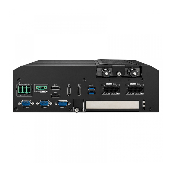
Page 24: Rear Panel I/O & Functions
You could turn on or off the system power by using this contact. This terminal block supports dual function of soft power-on/power-off (instant off or delay 4 second), and suspend mode. Pin No. Definition Ignition GETTING TO KNOW YOUR EVS-2000 LIQ... - Page 25 COM1 TO COM4 MB connector table : COM Port MB Connector COM Port MB Connector COM 1 COM 1 COM 2 COM 2 COM 3 COM 3 COM 4 COM 4 ©Vecow EVS-2000 LIQ User Manual GETTING TO KNOW YOUR EVS-2000 LIQ...
- Page 26 COM3 & COM4 MB connector pin out : Pin No. Signal Name Pin No. Signal Name COM1 to COM4 COM1 COM2 COM3 COM4 GETTING TO KNOW YOUR EVS-2000 LIQ...
- Page 27 7680 x 4320 resolution at 60Hz. Multi-Stream Transport Display Resolutions Table : Multi-Stream Transport Display Max. Resolution EVS-2000 Two panel Displays concurrently 7680 x 4320 @60Hz ©Vecow EVS-2000 LIQ User Manual GETTING TO KNOW YOUR EVS-2000 LIQ...
- Page 28 DIO2_GPO1 EXT_IN10 DIO2_GPI2 EXT_OUT10 DIO2_GPO2 EXT_IN11 DIO2_GPI3 EXT_OUT11 DIO2_GPO3 EXT_IN12 DIO2_GPI4 EXT_OUT12 DIO2_GPO4 EXT_IN13 DIO2_GPI5 EXT_OUT13 DIO2_GPO5 DIO1 EXT_IN14 DIO2_GPI6 EXT_OUT14 DIO2_GPO6 EXT_IN15 DIO2_GPI7 EXT_OUT15 DIO2_GPO7 GND_ISO_ +VDI_COM1 DIO1 GND_ISO_ +VDIO_EXT1 DIO1 (6~48V Input) GETTING TO KNOW YOUR EVS-2000 LIQ...
- Page 29 Device DIO Connector (NPN, Default) 6-48V DC DIO_VDC (Pin 20) DO (Pin11-18) DIO_GND (Pin10,19) Source Mode Device DIO Connector (PNP) 6-48V DC DIO_VDC (Pin 20) DO (Pin11-18) DIO_GND (Pin10,19) ©Vecow EVS-2000 LIQ User Manual GETTING TO KNOW YOUR EVS-2000 LIQ...
- Page 30 On / Off PIN 1 ~ 8 PIN 11 ~ 18 PIN 1 ~ 8 PIN 11 ~ 18 COM 1 COM 2 COM 3 Optional for PCIe x4 FHHL add on card or PCI card. GETTING TO KNOW YOUR EVS-2000 LIQ...
-
Page 31: Main Board Expansion Connectors
HDD_PWR1 HDD_PWR2 PCIEX4-1 DEBUG1 SODIMM2 COM2 JRI_PWR1 SODIMM1 COM1 JRI_PWR2 JCMOS1 COM3 COM4 M2M_CN1 BIOS JIGNMODE1 M2B_CN2 JHDA_SDO1 M2E_CN1 MPCIE1 SATA2 SATA1 SUMITB1 M2B_CN1 SYS_FAN1 SUMITA1 CN23 CN50 CN51 ©Vecow EVS-2000 LIQ User Manual GETTING TO KNOW YOUR EVS-2000 LIQ... - Page 32 The pin-outs of miscellaneous port are listed in following table : Group Pin No. Definition HDD_LED_P HDD LED HDD_LED_N FP_RST_BTN_N RESET BUTTON Ground PWR_LED_P POWER LED FP_PWR_BTN_P POWER BUTTON Ground GETTING TO KNOW YOUR EVS-2000 LIQ...
- Page 33 Slot Description SODIMM1 DDR4 Channel A SODIMM2 DDR4 Channel B 2.4.4 BIOS Socket (CN1) If the BIOS need to be changed, please contact the Vecow RMA service team. BIOS ©Vecow EVS-2000 LIQ User Manual GETTING TO KNOW YOUR EVS-2000 LIQ...
- Page 34 Standard, All Form Factor 1x4p Power Header There are 2 HDD power header on board and each power header supports Four 2.5" SATA HDD. HDD_PWR1 HDD_PWR2 Pin No. Description Pin No. Description +V12 (Max. 1.5A) Ground Ground +V5 (Max. 1.5A) GETTING TO KNOW YOUR EVS-2000 LIQ...
- Page 35 This pin header is through by LPC interface and pins define are listed in the following table. Pin No. Pin Name Pin No. Pin Name 3.3V SERIRQ FRAME# 24M CLCOK RESET 2.4.8 SUMIT Connector (SUMITA1/SUMITB1) SUMITB1 SUMITA1 ©Vecow EVS-2000 LIQ User Manual GETTING TO KNOW YOUR EVS-2000 LIQ...
- Page 36 SPI_MISO USB_OC# SPI_MOSI Reserved SPI_CLK SPI_CS10 USB_3+ SPI_CS1# USB_3- Reserved LPC_DRQ1# USB_2+ LPC_AD0 USB_2- LPC_AD1 LPC_AD2 USB_1+ LPC_AD3 USB_1- LPC_FRAME# SERIRQ# USB_0+ Reserved USB_0- CLK_33MHz A_PET_P0 A_PER_P0 A_PET_N0 A_PER_N0 APRSNT#/A_PE_CLKREQ# PERST# A_CLKP WAKE# A_CLKN GETTING TO KNOW YOUR EVS-2000 LIQ...
- Page 37 B_CLKP C_CLKN B_CLKN CPRSNT#/C_PE_CLKREQ# C_PET_P0 C_PER_P0 C_PET_N0 C_PER_N0 C_PET_P1 C_PER_P1 C_PET_N1 C_PER_N1 C_PET_P2 C_PER_P2 C_PET_N2 C_PER_N2 C_PET_P3 C_PER_P3 C_PET_N3 C_PER_N3 PERST# WAKE# Reserved Reserved Reserved +3.3V +3.3V +3.3V +5V_AUX ©Vecow EVS-2000 LIQ User Manual GETTING TO KNOW YOUR EVS-2000 LIQ...
- Page 38 Pin Out : Pin No. Description Pin No. Description Reserved +3.3Vaux Reserved Reserved +1.5V Reserved Reserved Reserved +3.3Vaux Reserved +3.3Vaux USB_D+ USB_D- PETp0 PETn0 SMB_DATA SMB_CLK +1.5V PERn0 PERp0 +3.3Vaux PERST# Reserved reserved Reserved Mechanical Key GETTING TO KNOW YOUR EVS-2000 LIQ...
- Page 39 Panasonic BR2032 190mAh lithium battery. It is recommended that you not replace the lithium battery on your own. If the battery needs to be changed, please contact the Vecow RMA service team. ©Vecow EVS-2000 LIQ User Manual GETTING TO KNOW YOUR EVS-2000 LIQ...
- Page 40 Fan speed sensor Fan PWM 2.4.12 MXM POWER (MXMPWR1) This connector provides +12V for MXM Graphic card only and the pin define are listed in the following table. MXAPWR1 Pin No. Description Pin No. Description GETTING TO KNOW YOUR EVS-2000 LIQ...
- Page 41 EVS-2000 provides 4 serial ports (COM1-COM4) headers for internal COM port cable and the pin define are listed in the following table. COM1 COM2 COM3 COM4 COM3 Pin No. Description Pin No. Description Ground ©Vecow EVS-2000 LIQ User Manual GETTING TO KNOW YOUR EVS-2000 LIQ...
- Page 42 2230. Pin Out : Pin No. Description Pin No. Description +V3.3_AUX +V3.3_AUX PCIE_CLK_REQ# M2E_REFCLK SMB_ALERT# SMB_CLK SMB_DATA M2E_WLAN_DISABLE PCIE_WAKE# M2E_BT_DISABLE PCIE_CLK_REQ0# PLTRST# SUS_CLK PCIE_100M_CLK__N PCIE_100M_CLK__P CNVI_BLANKING PCIE_RX_N CL_CLK PCIE_RX_P CL_DATA CL_RST_N GETTING TO KNOW YOUR EVS-2000 LIQ...
- Page 43 M.2 KEY M : PCIe x4/SATA Support M.2 key M connector is suitable for applications that use Host I/Fs supported by either PCIe or SATA, or Solid State Storage Devices (SSD). Module card types include 2280. M2M_CN1 ©Vecow EVS-2000 LIQ User Manual GETTING TO KNOW YOUR EVS-2000 LIQ...
- Page 44 2.4.16 M.2 KEY-B (M2B_CN1/M2B_CN2) M.2 KEY-B USB 3.0/USB 2.0 Support (default), PCIe x2 (BIOS option) M2B_CN1 Module card types include 3042/3052, and M2B_CN2 Module card types include 2280. M2B_CN2 M2B_CN1 GETTING TO KNOW YOUR EVS-2000 LIQ...
-
Page 45: Main Board Jumper Settings
To "open" a jumper, you remove the clip. Sometimes a jumper will have three pins, labeled 1, 2 and 3. In this case you would connect either pins 1 and 2, or 2 and 3. Open Closed Closed 2-3 ©Vecow EVS-2000 LIQ User Manual GETTING TO KNOW YOUR EVS-2000 LIQ... - Page 46 1 : ON 2 : OFF 2 : OFF 2 : ON 2.5.2 USB Power Jumper (JUSBPWR1) JUSBPWR1 Jumper Setting Function 1 : 2 Supported Wake Up (Default) JUSBPWR1 2 : 3 Non Wake Up support GETTING TO KNOW YOUR EVS-2000 LIQ...
- Page 47 1 - 2 +12V (1A max.) 3 - 4 5 - 6 COM3 RI (Default) JRI_PWR2 7 - 8 +12V (1A max.) 9 - 10 11 - 12 COM4 RI (Default) ©Vecow EVS-2000 LIQ User Manual GETTING TO KNOW YOUR EVS-2000 LIQ...
- Page 48 2.5.4 MXM VGA Disable (JP4) Jumper Setting Function 1 : 3 MXM VGA Enable 3 : 5 MXM VGA Disable 2.5.5 Clear CMOS JCMOS1 Jumper Setting Function 1 : 2 *Normal (Default) JCMOS1 2 : 3 Clear CMOS GETTING TO KNOW YOUR EVS-2000 LIQ...
- Page 49 HDA_SDO1 2 : 3 Disable Flash Descriptor Security (override) 2.5.7 Ignition Mode (JIGNMODE1) JIGNMODE1 Jumper Setting Function 1 : 2 H/W mode JIGNMODE1 2 : 3 S/W mode (default) ©Vecow EVS-2000 LIQ User Manual GETTING TO KNOW YOUR EVS-2000 LIQ...
-
Page 50: Ignition Control
EVS-2000 series provides 16 modes of different power on/off delay periods adjustable via SW2 switch. The default rotary switch is set to 0 in ATX/AT power mode. For the setting of software IGN, please refer to 4.4.3 GPIO Manager Control. GETTING TO KNOW YOUR EVS-2000 LIQ... - Page 51 30 minutes 5 seconds 1 hour 10 seconds 2 hours 10 seconds 4 hours 10 seconds 6 hours 10 seconds 8 hours 10 seconds 12 hours 10 seconds 24 hours ©Vecow EVS-2000 LIQ User Manual GETTING TO KNOW YOUR EVS-2000 LIQ...
- Page 52 9V to 50V DC. 3. For proper ignition control, the power button setting should be "Power Down" mode. In Windows for example, you need to set "When I press the power button" to Shut down. GETTING TO KNOW YOUR EVS-2000 LIQ...
-
Page 53: Chapter 3 System Setup
SYSTEM SETUP 3.1 How to Open Your EVS-2000-LIQ Step 1 Remove one F-M3x4L screw. Step 2 Remove one F-M3x4L (Red) and trigger and open PCI cover (Blue). ©Vecow EVS-2000 LIQ User Manual SYSTEM SETUP... - Page 54 Step 3 Remove six F-M3x4L screws. Step 4 Take off the bottom cover. SYSTEM SETUP...
- Page 55 Step 5 Finish. ©Vecow EVS-2000 LIQ User Manual SYSTEM SETUP...
-
Page 56: Installing Cpu
3.2 Installing CPU Step 1 Loosen the screw by turning it. Step 2 Remove Four P- M3x25 screws. And then remove the water-cooling head. SYSTEM SETUP... - Page 57 Step 3 Remove Nine F- M3x4 screws. And then remove the sheet metal. Step 4 Remove the six P-M3*6L screws from the top. ©Vecow EVS-2000 LIQ User Manual SYSTEM SETUP...
- Page 58 Step 4.1 Remove the four P-M3*6L screws on the right side and then remove the sink. Step 5 Open CPU slot. (Be careful CPU pin) SYSTEM SETUP...
- Page 59 Step 6 Installing CPU on the slot and remove the mylar. Step 7 Cover and lock the CPU socket. ©Vecow EVS-2000 LIQ User Manual SYSTEM SETUP...
- Page 60 Step 8 Apply thermal grease like "X". Step 9 Cover the sink and fasten the screws. SYSTEM SETUP...
-
Page 61: Installing Ddr4 So-Dimm Modules
3.3 Installing DDR4 SO-DIMM Modules Step 1 DDR4 RAM module into SO-DIMM slot. Step 2 Make sure the RAM module is locked by the memory slot. ©Vecow EVS-2000 LIQ User Manual SYSTEM SETUP... -
Page 62: Installing Mini Pcie Card
3.4 Installing Mini PCIe Card Step 1 Install Mini PCIe card into the Mini PCIe socket. Step 2 Fasten one M2.5 screw. SYSTEM SETUP... -
Page 63: Installing M.2 (Key B/E/M)
3.5 Installing M.2 (Key B/E/M) 3.5.1 Key B 2280, Key E 2230, Key M 2280 Step 1 Install M.2 card into the M.2 slot. Step 2 Fasten one PH-M3x4L screw. ©Vecow EVS-2000 LIQ User Manual SYSTEM SETUP... - Page 64 3.5.2 Key B 3042 Step 1 Install M.2 card into the M.2 slot. Step 2 Fasten one PH-M3x4L screw. SYSTEM SETUP...
- Page 65 Step 1 Change the stud position. Step 2 Then, it is able to install M.2 Key B 3052 module. Step 3 Install M.2 card into the M.2 slot and fasten one PH-M3x4L screw. ©Vecow EVS-2000 LIQ User Manual SYSTEM SETUP...
-
Page 66: Installing Antenna Cable
3.6 Installing Antenna Cable Step 1 Remove the rubber corks on the front and side. Step 2 Put antenna cable connector into the hole on panel. SYSTEM SETUP... - Page 67 Step 3 Fasten washer on the antenna cable connector. ©Vecow EVS-2000 LIQ User Manual SYSTEM SETUP...
-
Page 68: Installing Sim Card
3.7 Installing SIM Card Step 1 Remove two F-M3x4L screws on SD & SIM cover. Step 2 Inserting SIM Card, make sure the system power is not plugged. SYSTEM SETUP... -
Page 69: Installing Sd Card
3.8 Installing SD Card Step 1 Remove two F-M3x4L screws on SD & SIM cover. Step 2 Inserting SIM Card, make sure the system power is not plugged. ©Vecow EVS-2000 LIQ User Manual SYSTEM SETUP... -
Page 70: Installing Pci/Pcie Card
(*Based on the position of power connectors and the card sink/case design, not all expansion card within the maximum dimension can fit in to the system. Please consult the Vecow support team for confirmation.) Step 1 Check PCI/PCIe Slot supports the maximum length 200 mm (without card bracket) of PCI/PCIe expansion card. - Page 71 Step 3 Installing PCI/PCIe card and fasten M3x5L screws. ©Vecow EVS-2000 LIQ User Manual SYSTEM SETUP...
-
Page 72: Installing Ssd/Hdd
3.10 Installing SSD/HDD Step 1 Trigger and open SSD/HDD tray. Step 2 Insert 2.5" SSD/HDD in the tray and fasten two F-M3x4 screws. SYSTEM SETUP... - Page 73 Step 3 Finish. Step 4 Installing SSD/HDD. ©Vecow EVS-2000 LIQ User Manual SYSTEM SETUP...
-
Page 74: Mounting Your Evs-2000-Liq
3.11 Mounting Your EVS-2000-LIQ 3.11.1 Wall Mount Bracket for EVS-2000-LIQ with four M3x6L screws. 3.11.2 EVS-2000-LIQ VESA Mount Kit (75 x 75/100 x 100 mm) Step 1 Remove six F-M3x6L screws. SYSTEM SETUP... - Page 75 Step 2 Install VESA Mount and fasten six I-M3x6L screws. ©Vecow EVS-2000 LIQ User Manual SYSTEM SETUP...
- Page 76 3.11.3 EVS-2000-LIQ Din Rail with VESA Mount Kit Step 1 Remove six F-M3x6L screws. Step 2 Install Din Rail with VESA Mount Kit and fasten six I-M3x6L screws. SYSTEM SETUP...
-
Page 77: Chapter 4 Bios And Driver
Figure 4-1 : Entering Setup Screen BIOS provides an interface for users to check and change system configuration. The BIOS setup program is accessed by pressing the <Del> key when POST display output is shown. ©Vecow EVS-2000 LIQ User Manual BIOS AND DRIVER... -
Page 78: Main
4.2 Main Figure 4-2 : BIOS Main Menu The main menu displays BIOS version and system information. There are two options on Main menu. System Date Set the date. Use <Tab> to switch betwe en date elements. System Time Set the time. Use <Tab> to switch between time elements. 4.3 Advanced Figure 4 3 : BIOS Advanced Menu Select advanced tab to enter advanced BIOS setup options, such as CPU... - Page 79 Enable/disable CPU Advanced Encryption Standard instructions. Intel Trusted Execution Technology ® Enables utilization of additional hardware capabilities provided by Intel Trusted Execution Technology. Changes require a full power cycle to take effect. ©Vecow EVS-2000 LIQ User Manual BIOS AND DRIVER...
- Page 80 4.3.2 Power & Performance Figure 4 3-2 : Power & Performance 4.3.2.1 CPU – Power Management Control Figure 4 3-2-1 : CPU – Power Management Control Boot performance mode Select the performance state that the BIOS will set before OS handoff. Intel (R) SpeedStep (tm) Allows more than two frequency ranges to be supported.
- Page 81 MEBx Setup. AMT Configuration ® Configure Intel Active Management Technology Parameters. ME Unconfig on RTC Clear State Disabling this option will cause ME not to unconfigure on RTC clear. ©Vecow EVS-2000 LIQ User Manual BIOS AND DRIVER...
- Page 82 4.3.4 Trusted Computing Figure 4 3-4 : Trusted Computing Control the TPM device status and display related information if TPM chip is present. 4.3.5 ACPI Settings Figure 4 3-5 : ACPI Settings Enable Hibernation Enables or disables system's ability to hibernate (OS/S4 sleep state). This option may not be effective with some OS.
- Page 83 Options for Serial Port 1 to Serial Port 4. Entering the corresponding Port option then end user can change the settings such as I/O resource and UART mode (High Speed Serial Port is Port 1 only). ©Vecow EVS-2000 LIQ User Manual BIOS AND DRIVER...
- Page 84 4.3.8 Hardware Monitor Figure 4-3-8 : Hardware Monitor Settings The IT8786 SIO features an enhanced hardware monitor providing thermal, fan speed, and system voltages' status monitoring. Smart Fan Support Smart Fan Support. Work with Full Speed if "Smart Fan Support" is Disabled. Smart Fan Mode Default : Using the default smart fan table.
- Page 85 Legacy Console Redirection Settings. Serial Port for Out-of-Band Management/Windows Emergency Management Services (EMS) Console redirection enable or disable. 4.3.10 Intel TXT Information Figure 4-3-10 : Intel TXT Information Display Intel TXT information ©Vecow EVS-2000 LIQ User Manual BIOS AND DRIVER...
- Page 86 4.3.11 Acoustic Management Configuration Figure 4-3-11 : Acoustic Management Settings Acoustic Management Configuration Option to enable or disable automatic acoustic management. 4.3.12 PCI Subsystem Setting Figure 4-3-12 : PCI Subsystem Settings Above 4G Decoding Globally Enables or Disables 64-bit capable Devices to be Decoded in Above 4G Address Space (Only if System Supports bot PCI Decoding) Hot-Plug Support Globally Enables or Disables Hot-Plug support for the entire System.
- Page 87 Wait time to press ESC key to abort the PXE boot. Media detect count Number of times presence of media will be checked. 4.3.14 AMC6821 Configuration Figure 4-3-14 : AMC6821 Settings Fan1 Speed There are three level for Fan1 Control. [High/Middle/Low] ©Vecow EVS-2000 LIQ User Manual BIOS AND DRIVER...
- Page 88 4.3.15 NVMe Configuration Figure 4-3-15 : NVMe Settings Display NVMe controller and Drive information. 4.3.16 USB Configuration Figure 4-3-16 : USB Settings Legacy USB Support Enables Legacy USB support. AUTO option disables Legacy support if no USB devices are connected. DISABLE option will keep USB devices available only for EFI applications.
- Page 89 This should be enabled only if both WWAN and WLAN solutions are based on Intel components. Discrete Bluetooth Module SerialIo UART0 needs to be enabled to select BT Module Advanced settings Configure ACPI objects for wireless devices WWAN Configuration Configure WWAN related options ©Vecow EVS-2000 LIQ User Manual BIOS AND DRIVER...
- Page 90 4.3.18 SDIO Configuration Figure 4-3-18 : SDIO Settings SDIO Access Mode [Auto] : Access SD device in DMA mode if controller supports it, otherwise in PIO mode. [DMA] : Access SD device in DMA mode. [PIO] : Access SD device in PIO mode. BIOS AND DRIVER...
-
Page 91: Chipset
4.4.1 System Agent (SA) Configuration Figure 4-4-1 : System Agent Settings VT-d VT-d capability. Above 4GB MMIO BIOS assignment Enable/disable above 4GB MemoryMappedIO BIOS assignment. This is disabled automatically when aperture size is set to 2048MB. ©Vecow EVS-2000 LIQ User Manual BIOS AND DRIVER... - Page 92 4.4.1.1 Memory Configuration Figure 4-4-1-1 : Memory Information Displays memory information. 4.4.1.2 Graphics Configuration Figure 4-4-1-2 : Graphics Settings Skip Scaning of External Gfx Card If Enable, it will not scan for External Gfx Card on PEG and PCH PCIE Ports. Primary Display Select which of IGFX/PEG/PCI Graphics device should be Primary Display Or select SG for Switchable Gfx.
- Page 93 Specify what state to go to when power is re-applied after a power failure (G3 state). S0 State : Always turn-on the system when power source plugged-in. S5 State : Always turn-off the system when power source plugged-in. ©Vecow EVS-2000 LIQ User Manual BIOS AND DRIVER...
- Page 94 4.4.2.1 PCI Express Configuration of PCH-IO Figure 4-4-2-1 : PCH-IO Settings DMI Link ASPM Control Enable/Disable the control of Active State Power Management on SA side of the DMI Link. Native PCIE Enable PCIE Express Native Support Enable/Disable. PCI Express device settings Bios options for PCI Express device setting.
- Page 95 Identifies that the SATA port is connected to solid state drive or hard disk drive. 4.4.2.3 Security Configuration Figure 4-4-2-3 : Security Settings BIOS Lock Enable/Disable the PCH BIOS Lock Enable (BLE bit) feature. ©Vecow EVS-2000 LIQ User Manual BIOS AND DRIVER...
- Page 96 4.4.3 GPIOManager Control Figure 4-4-3 : GPIOManager Settings DVI/VGA DDC channel selection DVI/VGA DDC channel selection for DVI-I connector System Fan 2 Speed System Fan 2 Speed control (SYS_FAN2) Ignition F/W Version Indicate current ignition f/w version Current Ignition control method [Hardware] Ignition mode control by hardware switch.
-
Page 97: Security
4.5 Security Figure 4-5 : BIOS Security Menu Administrator Password Set administrator password. User Password Set user password. Secure Boot Customizable Secure Boot Settings. ©Vecow EVS-2000 LIQ User Manual BIOS AND DRIVER... - Page 98 4.5.1 HDD Security Configuration Figure 4-5-1 HDD Security Settings Set User Password Set HDD user password. *** Advisable to power cycle system after setting hard disk passwords *** Discard or save changes option in setup does not have any impact on HDD when password is set or removed.
-
Page 99: Boot
Sets the system boot order. New Boot Option Policy Controls the placement of newly detected UEFI boot options. Hard Drive BBS Priorities Set the order of the Legacy devices in this group. ©Vecow EVS-2000 LIQ User Manual BIOS AND DRIVER... -
Page 100: Save & Exit
4.7 Save & Exit Figure 4-7 : Bios Save and Exit Menu Save Changes and Exit Exit system setup after saving the changes. Discard Changes and Exit Exit system setup without saving any changes. Save Changes and Reset Reset the system after saving the changes. Discard Changes and Reset Reset system setup without saving any changes. -
Page 101: Appendix A : Isolated Dio Guide
POE 1 POE 3 Do NOT use these functions in right : 1. PE-2000 : DIO1 (ID = 0), POE 2. PE-3000 : POE (ID = 0) 3. UE-1000 : USB (ID = 0) Appendix A ©Vecow EVS-2000 LIQ User Manual... - Page 102 A.2 Isolated DIO Signal Circuit DI Reference Circuit : Sink Mode (NPN) Power DIO Connector Supply DI_COM (Pin 9) 6-48V DC DI (Pin1-8) Source Mode (PNP) Power DIO Connector Supply DI_COM (Pin 9) 6-48V DC DI (Pin1-8) DO Reference Circuit : Sink Mode Device DIO Connector...
- Page 103 Header folders include head file for software developer or System Integration. Manual folders include API description. Sample folders include sample program, driver library, and API library for Windows/ Linux Source folders include sample program source code that compile on Visual Studio 2008/ubuntu16.04. Appendix A ©Vecow EVS-2000 LIQ User Manual...
- Page 104 A.4 Sample Execute demo tool. Windows Linux Sample, as shown below : Vecow_DIO Vecow_DIO_loopback Vecow_POE Vecow_WDT Appendix A...
-
Page 105: Appendix B : Software Functions
APPENDIX B : Software Functions B.1 Driver API Guide In Header folder, Vecow.h and VecowLinux.h contain usabled API for Windows/Linux. BOOL initial_SIO(BYTE Isolate_Type, BYTE DIO_NPN) Initial machine for IO and watch dogtimer. Isolate_Type : DIO type. 1 : Isolated DIO;... - Page 106 BOOL set_IO1_configuration(BYTE Iso, BYTE DI_mode, BYTE DO_mode, WORD Mask) BOOL set_IO2_configuration(BYTE Iso, BYTE DI_mode, BYTE DO_mode, WORD Mask) Set DIO configuration. Isolate_Type : DIO type. 1 : Isolated DIO; 0 : Non-Isolated DIO(GPIO). DI_mode ([7:0]) : DI type, pin setting by hexadecimal bitmask only for Isolated DIO. 0xFF : PNP (Source) mode for European rule;...
- Page 107 TRUE (1) : Success. FALSE (0) : Fail (Initial error, or setup 0, or hardware problem). BOOL cancel_WDT() Cancel watchdog timer. Return : TRUE (1) : Success. FALSE (0) : Fail (Initial error or hardware problem). Appendix B ©Vecow EVS-2000 LIQ User Manual...
- Page 108 BOOL initial_POE(BYTE Scan, BYTE ID) Initial POE. Scan : POEID scan type 2 : Auto scan; 1 : Manual setup. ID : POE ID by manual setting. Range : 0~15. Return : TRUE (1) : Success. FALSE (0) : Fail (Driver not exists, or version is too old, or out of range error). BOOL get_POE_configuration(BYTE ID, BYTE *Auto, BYTE *Mask) Get POE configuration (by variable).
- Page 109 B. POE ([3:0]) : POE state, pin setting by hexadecimal bitmask. 1 : On; 0 : Off. Return : TRUE (1) : Success. FALSE (0) : Fail (Initial error, or out of range error, or hardware problem). Appendix B ©Vecow EVS-2000 LIQ User Manual...
-
Page 110: Appendix C : Raid Functions
APPENDIX C : RAID Functions C.1.1 SATA Mode for RAID Please select SATA Device to RAID mode on BIOS menu. Chipset → PCH-IO Configuration → SATA And RST Configuration → SATA Mode Selection → Intel RST Premium → Save Changes and Reset. C.1.2 UEFI Mode for RAID 1. - Page 111 The system is featured with one M.2 key B, one M.2 key M for NVME, one mSATA slot, and including two internal SATA. We used SATA for Windows 10 OS installation as an example. Appendix C ©Vecow EVS-2000 LIQ User Manual...
- Page 112 C.3 To Install All Device Drivers of the System The instructions are as follows : 1. Install Chipset driver 2. Install Network driver 3. Install ME driver (if available) 4. Install Audio driver 5. Install VGA driver C.4 To Install "Intel Rapid Storage Technology" Software You can get the latest information and the software directly from Intel website.
- Page 113 Then add "Logical Device" for Windows access. C.8 If One SATA HDD on RAID Volume is Out-of-use After RAID 1 volume is created, you can see the figure of SATA device allocation. HDD CAUTION Sign Appendix C ©Vecow EVS-2000 LIQ User Manual...
- Page 114 C.9 Recovery and Auto Re-build When Using the SAME RAID HDD C.10 Recovery and Auto Re-build When Using DIFFERENT RAID HDD A warning will pop-up to ask you if the disk is not a member of the original RAID volume. If you press "Rebuild", it will replace the broken SATA HDD to the last SATA HDD of RAID volume.
-
Page 115: Appendix D : Power Consumption
LAN 1 (i219) 1.0 Gbps LAN 2 (i210) 1.0 Gbps Graphics output Power plan Balance (Windows10 Power plan) Power Source Chroma 62006P-100-25 Test Program-1 BurnInTest 8.1 Test Program-2 FurMark 1.21.2.0 (1920 x 1080, 8X MSAA) Appendix D ©Vecow EVS-2000 LIQ User Manual... - Page 116 D.1 Intel® Core™ i5-10500E (12M Cache, 3.10GHz) Power on and boot to Win 10 (64-bit) Power on and boot to Win 10 (64-bit) Standby Mode Idle status CPU Power Sleep Mode usage less 3% Input Current Consumption Current Consumption Current Consumption Core™...
- Page 117 7.013A 63.12W i5-10500E Core™ 3.288A 39.45W 5.283A 63.40W i5-10500E Core™ 1.770A 42.48W 2.679A 64.29W i5-10500E Core™ 1.247A 44.87W 1.867A 67.22W i5-10500E Core™ 0.987A 47.40W 1.459A 70.01W i5-10500E Core™ 0.959A 47.93W 1.409A 70.44W i5-10500E Appendix D ©Vecow EVS-2000 LIQ User Manual...
- Page 118 D.3 Intel® Core™ i5-10500E (12M Cache, 3.10GHz) with MX RTX 2070 Power on and boot to Win 10 (64-bit) Power on and boot to Win 10 (64-bit) Standby Mode Idle status CPU Power Sleep Mode usage less 3% Input Current Consumption Current Consumption...
- Page 119 Consumption Current Consumption Core™ 5.224A 62.69W 8.723A 104.68W i5-10500E Core™ 2.706A 64.94W 4.502A 108.05W i5-10500E Core™ 1.892A 68.11W 3.113A 112.07W i5-10500E Core™ 1.495A 71.76W 2.427A 116.50W i5-10500E Core™ 1.439A 71.95W 2.319A 115.95W i5-10500E Appendix D ©Vecow EVS-2000 LIQ User Manual...
- Page 120 D.5 Intel® Core™ i5-10500E (12M Cache, 3.10GHz) with MXM P2000 Power on and boot to Win 10 (64-bit) Power on and boot to Win 10 (64-bit) Standby Mode Idle status CPU Power Sleep Mode usage less 3% Input Current Consumption Current Consumption Current...
- Page 121 Consumption Current Consumption Core™ 5.155A 61.86W 10.170A 122.04W i5-10500E Core™ 2.651A 63.62W 5.186A 124.46W i5-10500E Core™ 1.877A 67.58W 3.537A 127.34W i5-10500E Core™ 1.447A 69.45W 2.734A 131.24W i5-10500E Core™ 1.393A 69.65W 2.617A 130.85W i5-10500E Appendix D ©Vecow EVS-2000 LIQ User Manual...
- Page 122 D.7 Intel® Core™ i5-10500E (12M Cache, 3.10GHz) with MXM GTX 1050 Power on and boot to Win 10 (64-bit) Power on and boot to Win 10 (64-bit) Standby Mode Idle status CPU Power Sleep Mode usage less 3% Input Current Consumption Current Consumption...
-
Page 123: Appendix E : Supported Memory & Storage List
Memory Test V5.01 BurnInTest V8.1 E.2 Test Item Remove Channel Memory Test Burn In Flash BIOS Battery PASS PASS PASS PASS *1 (Socket 1) PASS PASS PASS *1 (Socket 2) PASS PASS PASS Appendix E ©Vecow EVS-2000 LIQ User Manual... - Page 124 128GB Kingston SUV500/120G 120GB FORESEE FSGPMMC-256G 256GB M.2 M Key INTEL SSD 760p 128GB NVMe SAMSUNG 970 EVO Plus 250GB M.2 B Key Kingston SA1000MB/240G 240GB NVMe ** If more help is needed, please contact Vecow Technical Support.** Appendix E...
-
Page 125: Appendix F : Install Win11 (Bios Tpm Setting)
APPENDIX F : Install Win11 (BIOS TPM Setting) Step 1 Click on “Advanced”, then click on “PCH-FW Configuration” Step 2 Click on “PTT Configuration” Appendix F ©Vecow EVS-2000 LIQ User Manual... - Page 126 Step 3 Click on “dTPM” (TPM Device Selection) Step 4 Please save the BIOS settings by pressing F4. Please press Enter when the pop-up window which asks “Save configuration and exit?” appears. The computer will then restart. Appendix F...
- Page 127 Step 5 Click on “Trusted Computing” Step 6 If the window shows “TPM2.0 Device Found Firmware Version:5.62”, then the setting is completed. ** If more help is needed, please contact Vecow technical support ** Appendix F ©Vecow EVS-2000 LIQ User Manual...
- Page 128 No part of this publication may be reproduced in any form or by any means, electric, photocopying, or recording, without prior authorization from the publisher. The rights of all the brand names, product names, and trademarks belong to their respective owners. © Vecow Co., Ltd. 2023. All rights reserved.
Need help?
Do you have a question about the EVS-2000 LIQ and is the answer not in the manual?
Questions and answers