
Related Manuals for Vecow GPC-1000 Series


Summary of Contents for Vecow GPC-1000 Series
- Page 1 USER USER GPC-1000 Manual Manual Intel ® Xeon ® /Core™ i7/i5/i3 Dual GPU AI Computing System Workstation-grade, NVIDIA ® Tesla ® /Quadro ® /GeForce ® Graphics 1.0.0 Edition 20200519...
- Page 2 Record of Revision Version Date Page Description Remark 0.10 2020/05/11 Preliminary Release 1.00 2020/05/19 Official Release ©Vecow GPC-1000 User Manual...
- Page 3 This manual is released by Vecow Co., Ltd. for reference purpose only. All product offerings and specifications are subject to change without prior notice. Vecow Co., Ltd. is under no legal commitment to the details of this document. Vecow shall not be liable for direct, indirect, special, incidental, or consequential damages arising out of the use of this document, the products, or any third party infringements, which may result from such use.
- Page 4 Tray, 4 USB 3.1, 4 COM, 1 SIM, 16 Isolated DIO CPU List Series Cores GHz Cores GHz E-2278GE E-2176G ® Intel E-2278GEL ® Xeon E-2124G E-2226GE i7-8700 i7-9700E i7-8700T i7-9700TE i5-8500 i5-9500E ® Intel Core ™ i5-8500T i5-9500TE i3-8100 i3-9100E i3-8100T i3-9100TE ©Vecow GPC-1000 User Manual...
- Page 5 Terminal Block 20-pin to Terminal Block 20-pin Cable, 500cm Terminal Board with One 20-pin Terminal Block Connector and TMB-TMBK-20P DIN-Rail Mounting 4G Module Mini PCIe 4G/GPS Module with Antenna WiFi & Bluetooth WiFi & Bluetooth Module with Antenna ©Vecow GPC-1000 User Manual...
-
Page 6: Table Of Contents
3.2 Installing CPU 3.3 Installing DDR4 SO-DIMM Modules 3.4 Installing Mini PCIe Card 3.5 Installing SIM Card 3.6 Installing PCI/PCIe Card 3.7 Installing SSD/HDD 3.8 Installing Antenna Cable 3.9 Mount Your GPC-1000 3.10 Installing Hold-down Kit ©Vecow GPC-1000 User Manual... - Page 7 APPENDIX A : Isolated DIO Guide APPENDIX B : Software Functions APPENDIX C : RAID Functions APPENDIX D : Power Consumption APPENDIX E : Supported Memory & Storage List APPENDIX F : How to Install Power Supply ©Vecow GPC-1000 User Manual...
-
Page 8: Chapter 1 General Introduction
GPU to accelerate AI solutions development and deployment. Vecow GPC-1000 Series provides highly flexible configuration with 4 PCIe slot including 2 PCIe x8, 1 PCIe x4 and 1 PCIe x1. Additionally, GPC-1000 Series, ® which runs on NVIDIA... -
Page 9: Features
• 2 DDR4 2666MHz SO-DIMM, up to 64GB • 4 External USB 3.1 support up to 10Gbps data transfer • Supports WiFi/4G/3G/LTE/GPRS/UMTS • 2 SATA III, 4 COM RS-232/422/485, 16 Isolated DIO • Optional supports 5G Networks, 10G PoE ©Vecow GPC-1000 User Manual GENERAL INTRODUCTION... -
Page 10: Product Specification
• 2 DisplayPort : Up to 4096 x 2304 @60Hz • By requested Graphics Card Storage SATA 2 SATA III (6Gbps) support S/W RAID 0,1 mSATA 1 SATA III (Mini PCIe Type, 6Gbps) Storage Device 2 internal 2.5" SSD/HDD bracket ©Vecow GPC-1000 User Manual GENERAL INTRODUCTION... - Page 11 -40°C to 85°C (-40°F to 185°F) Humidity 5% to 95% Humidity, non-condensing Relative Humidity 95% at 60°C • IEC 61373 : 2010 Shock • Railway Applications : Rolling Stock Equipment, Shock and Vibration Test CE, FCC, EN50155, EN50121-3-2 ©Vecow GPC-1000 User Manual GENERAL INTRODUCTION...
-
Page 12: Supported Cpu List
Xeon E-2124G E-2226GE i7-8700 i7-9700E i7-8700T i7-9700TE i5-8500 i5-9500E ® Intel ™ Core i5-8500T i5-9500TE i3-8100 i3-9100E i3-8100T i3-9100TE 1.5 Mechanical Dimension 1.5.1 Dimensions of GPC-1000 Unit : mm (inch) 369.2 (14.54”) 242.7 (9.56”) ©Vecow GPC-1000 User Manual GENERAL INTRODUCTION... -
Page 13: Chapter 2 Getting To Know Your Gpc-1000
GETTING TO KNOW YOUR GPC-1000 2.1 Packing List Item Description GPC-1000 Vecow Drivers & Utilities DVD Item Description Outlook Usage PHILLPIS M4x16L with Mount 53-24D6416-30B washer, Ni PHILLPIS Mini PCIe 53-2426906-30B M2.5x6L, Ni slot KHS#6-32x6 Wall mount screw for 53-I000510-000... -
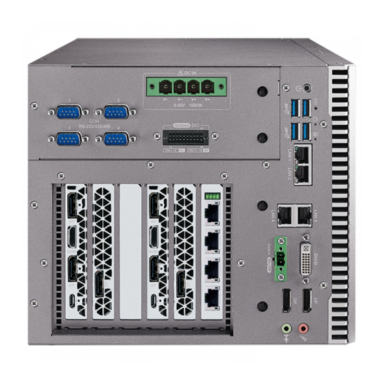
Page 14: Front Panel I/O Functions
2.2 Front Panel I/O Functions In Vecow GPC-1000 series family, all I/O connectors are located on the front panel. Most of the general connections to computer device, such as USB, LAN Jack, Audio, Display Port, DVI-D and other additional storage, are placed on the front panel. - Page 15 Please do note that a 4-second interval between each 2 power-on/power-off operation is necessary in normal working status. (For example, once turning off the system, you have to wait for 4 seconds to initiate another power-on operation.) ©Vecow GPC-1000 User Manual GETTING TO KNOW YOUR GPC-1000...
- Page 16 Power LED/Green : If the LED is solid green, it indicates that the system is powered on. LED Color Indication System Status • On/Off : Storage status, function or not Yellow • Twinkling : Data transferring Green Power System power status (on/off) ©Vecow GPC-1000 User Manual GETTING TO KNOW YOUR GPC-1000...
- Page 17 Multi-Stream Transport Display Resolutions Table : Multi-Stream Transport Display Max. Resolution One panel Display 4096 x 2304 @60Hz Two panel Displays concurrently 2880 x 1800 @60Hz Three panel Displays concurrently 2304 x 1440 @60Hz ©Vecow GPC-1000 User Manual GETTING TO KNOW YOUR GPC-1000...
- Page 18 1000Mbps Ethernet network; The left LED will keep twinkling/off when Ethernet data packets are being transmitted/received. ©Vecow GPC-1000 User Manual GETTING TO KNOW YOUR GPC-1000...
- Page 19 To utilize the audio function in Windows platform, you need to install the ® corresponding drivers for both Intel C236 chipset and Realtek ALC892 codec. 2.2.9 SSD/HDD Tray There are 4 front-access 2.5" SSD/HDD trays in the front side of GPC-1000. ©Vecow GPC-1000 User Manual GETTING TO KNOW YOUR GPC-1000...
-
Page 20: Main Board Expansion Connectors
JPS2 JCOMS1 SYS_FAN1 DCIN1 JP10 BAT1 CPU_FAN1 JDIO1 PCIE1 JDIO2 SIM1 COM4 COM3 COM2 COM1 MPCIE2 JP12 SODIMM_1 SODIMM_2 SUNITB1 JP11 PWR_BTN1 SUNITA1 JUSB1 AUDIO1 PWR1 LAN2 LAN1 USB32 USB31 DVID1 ©Vecow GPC-1000 User Manual GETTING TO KNOW YOUR GPC-1000... - Page 21 The pinouts of Miscellaneous port are listed in following table : Group Pin No. Description HDD_LED_P HDD LED HDD_LED_N FP_RST_BTN_N RESET BUTTON Ground PWR_LED_P POWER LED PWR_LED_N PWR_BTN_P POWER BUTTON Ground ©Vecow GPC-1000 User Manual GETTING TO KNOW YOUR GPC-1000...
- Page 22 SODIMM_1 SODIMM_2 Slot Description SODIMM_1 DDR4 Channel A SODIMM_2 DDR4 Channel B 2.3.4 CN1 : BIOS Socket If the BIOS need to be changed, please contact the Vecow RMA service team. ©Vecow GPC-1000 User Manual GETTING TO KNOW YOUR GPC-1000...
- Page 23 Standard, all form factor 1x4p power header There are 2 HDD power header on board and each power header supports two 2.5" SATA HDD. Pin No. Description Pin No. Description +12V ©Vecow GPC-1000 User Manual GETTING TO KNOW YOUR GPC-1000...
- Page 24 The USB interface is accessed through one standard USB 2.0 connector. This USB 2.0 does not support wake up function. JUSB1 Pin No. Definition Pin No. Definition USB_VCC USB_VCC USB_VCC USBD1- USBD1+ USBD2- USBD2+ ©Vecow GPC-1000 User Manual GETTING TO KNOW YOUR GPC-1000...
- Page 25 Reserved +3.3Vaux USB_D+ USB_D- PETp0 PETn0 SMB_DATA SMB_CLK +1.5V PERp0 PERn0 +3.3Vaux PERST# Reserved reserved Reserved Mechanical Key Reserved REFCLK+ Reserved REFCLK- Reserved Reserved CLKREQ# Reserved Reserved 1.5V Reserved WAKE# 3.3Vaux ©Vecow GPC-1000 User Manual GETTING TO KNOW YOUR GPC-1000...
- Page 26 Reserved +3.3Vaux USB_D+ USB_D- PETp0 PETn0 SMB_DATA SMB_CLK +1.5V PERp0 PERn0 +3.3Vaux PERST# Reserved reserved Reserved Mechanical Key UIM_VPP REFCLK+ UIM_RESET REFCLK- UIM_CLK UIM_DATA CLKREQ# UIM_PWR Reserved 1.5V Reserved WAKE# 3.3Vaux ©Vecow GPC-1000 User Manual GETTING TO KNOW YOUR GPC-1000...
- Page 27 Panasonic BR2032 190mAh lithium battery. It is recommended that you not replace the lithium battery on your own. If the battery needs to be changed, please contact the Vecow RMA service team. BAT1 2.3.11 CPU_FAN1, SYS_FAN1 : FAN Connector...
- Page 28 GPI or GPO. Detail setting see APPENDIX. JDIO1 and JDIO2 Pin define are as below. JDIO2 JDIO1 Pin No. JDIO1 Definition JDIO2 Definition SIO_GPO70 SIO_GPI80 SIO_GPO71 SIO_GPI81 SIO_GPO72 SIO_GPI82 SIO_GPO73 SIO_GPI83 SIO_GPO74 SIO_GPI84 SIO_GPO75 SIO_GPI85 SIO_GPO76 SIO_GPI86 SIO_GPO77 SIO_GPI87 ©Vecow GPC-1000 User Manual GETTING TO KNOW YOUR GPC-1000...
- Page 29 RS-485 w/z auto-flow control Pin Out : COM Port MB Connector COM Port MB Connector COM1 COM1 COM2 COM2 COM3 COM3 COM4 COM4 Pin No. Signal Name Pin No. Signal Name COM1 to 4 ©Vecow GPC-1000 User Manual GETTING TO KNOW YOUR GPC-1000...
- Page 30 The LCD inverter is connected to J6 via a JST 7-pin, 2.5mm connector providing +5V/+12V power to LCD display. The pin assignments are listed in the following table : Pin No. Definition Pin No. Definition +12V +12V LBKLT_CTL LBKLT_EN ©Vecow GPC-1000 User Manual GETTING TO KNOW YOUR GPC-1000...
- Page 31 GPC-1000 supports 12V DC power input by wire-to-board connector on the top side. Pin No. Definition Pin No. Definition +12V +12V +12V 2.3.18 CN4 : PCIe Riser Slot CN4 slot is used to connect with GPC-1000 Backplane. ©Vecow GPC-1000 User Manual GETTING TO KNOW YOUR GPC-1000...
-
Page 32: Jumper Settings
To "open" a jumper, you remove the clip. Sometimes a jumper will have three pins, labeled 1, 2 and 3. In this case you would connect either pins 1 and 2, or 2 and 3. Open Closed Closed 2-3 ©Vecow GPC-1000 User Manual GETTING TO KNOW YOUR GPC-1000... - Page 33 LVDS power input; closing Pin 2 and Pin 3 is for 5V LVDS power input. Pin No. Definition +3.3V (Default) 2.4.3 JCMOS1 : Clear CMOS JCMOS1 CMOS Header Normal Clear CMOS ©Vecow GPC-1000 User Manual GETTING TO KNOW YOUR GPC-1000...
- Page 34 2.4.4 JP11 : External USB 3.0/2.0 Power Select JP11 Pin No. Power +5V Standby Power +5V System Power 2.4.5 JP2 : Backlight Control Level Select Pin No. Definition 3.3V ©Vecow GPC-1000 User Manual GETTING TO KNOW YOUR GPC-1000...
- Page 35 JP9, JP10 logic setting are listed in the following table. Logic JP10 Logic JP9, JP10 PCI Express configurations are listed in the following table. JP10 PCI Express* Bifurcation 1 x8 PCI Express* 2 x8 PCI Express* 1 x16 PCI Express* ©Vecow GPC-1000 User Manual GETTING TO KNOW YOUR GPC-1000...
-
Page 36: Riser Board Connectors
DC_OUT2 DC_OUT1 FAN2 FAN1 DC_IN2 DC_IN1 DC_OUT_MB 2.5.1 DC_IN1, DC_IN2 : DC INPUT Power Connector Pin No. Definition Pin No. Definition +12V +12V +12V +12V +12V +12V +12V +12V ©Vecow GPC-1000 User Manual GETTING TO KNOW YOUR GPC-1000... - Page 37 FAN 1 and FAN 2 are listed in the following table. FAN1 : Pin No. Definition Pin No. Definition +12V Fan speed sensor FAN PWM FAN2 : Pin No. Definition Pin No. Definition +12V ©Vecow GPC-1000 User Manual GETTING TO KNOW YOUR GPC-1000...
-
Page 38: Power Board Connectors
+12V +12V +12V +12V +12V +12V 2.6.3 SYS FAN : Fan Connector The pin assignments of SYS FAN is listed in the following table. Pin No. Definition Pin No. Definition +12V ©Vecow GPC-1000 User Manual GETTING TO KNOW YOUR GPC-1000... -
Page 39: Dc- In Board Connectors
2.7.1 CN1 : DC INPUT POWER CONNECTOR Pin No. Definition Pin No. Definition DCIN DCIN 2.7.2 CN2, CN3, CN4, CN5 : DC OUTPUT POWER CONNECTOR Pin No. Definition Pin No. Definition DC_OUT DC_OUT ©Vecow GPC-1000 User Manual GETTING TO KNOW YOUR GPC-1000... -
Page 40: Chapter 3 System Setup
SYSTEM SETUP 3.1 How to Open Your GPC-1000 Step 1 Remove bottom eleven F#6-32. Step 2 Open bottom cover and remove power tray four F#6-32. Step 3 Finish. ©Vecow GPC-1000 User Manual SYSTEM SETUP... -
Page 41: Installing Cpu
3.2 Installing CPU Step 1 Open CPU Slot cover. Step 2 Install CPU into the CPU Slot. Step 3 Close and lock CPU Slot cover. ©Vecow GPC-1000 User Manual SYSTEM SETUP... -
Page 42: Installing Ddr4 So-Dimm Modules
3.3 Installing DDR4 SO-DIMM Modules Step 1 Install DDR4 RAM module into SO-DIMM slot. Step 2 Make sure the RAM module is locked by the memory slot. ©Vecow GPC-1000 User Manual SYSTEM SETUP... -
Page 43: Installing Mini Pcie Card
3.4 Installing Mini PCIe Card Step 1 Install Mini PCIe card into the Mini PCIe slot. Step 2 Fasten one M2.5 screw. ©Vecow GPC-1000 User Manual SYSTEM SETUP... -
Page 44: Installing Sim Card
3.5 Installing SIM Card Step 1 Open the SIM card cover. Step 2 Install SIM card into the SIM card slot and then close and lock the SIM card cover. ©Vecow GPC-1000 User Manual SYSTEM SETUP... -
Page 45: Installing Pci/Pcie Card
3.6 Installing PCI/PCIe Card Step 1 Please align the gold finger of the PCIE card with the slot. Step 2 Press down the graphics card. ©Vecow GPC-1000 User Manual SYSTEM SETUP... - Page 46 Step 3 Lock screw. Step 4 Finish. ©Vecow GPC-1000 User Manual SYSTEM SETUP...
-
Page 47: Installing Ssd/Hdd
3.7 Installing SSD/HDD Step 1 Open HDD/SSD tray. Step 2 Push the HDD/SSD into the slot. ©Vecow GPC-1000 User Manual SYSTEM SETUP... - Page 48 Step 3 Fasten four M3 screw. ©Vecow GPC-1000 User Manual SYSTEM SETUP...
-
Page 49: Installing Antenna Cable
3.8 Installing Antenna Cable Step 1 Check Antenna cable and washers. Step 2 Put Antenna cable connector into the hole on rear panel and fasten the washer 1, washer 2 and washer 3 on Antenna cable connector. ©Vecow GPC-1000 User Manual SYSTEM SETUP... -
Page 50: Mount Your Gpc-1000
3.9 Mount Your GPC-1000 Step 1 Ensure the screw holes on the right and left side of upper case match the ones on GPC-1000 wall mount bracket. Step 2 Fasten four #6-32 screws then finish. ©Vecow GPC-1000 User Manual SYSTEM SETUP... -
Page 51: Installing Hold-Down Kit
3.10 Installing Hold-down Kit Hold-down Kit Step 1 Hold two brackets to the graphics card. Step 2 Fasten four M3 screws. ©Vecow GPC-1000 User Manual SYSTEM SETUP... - Page 52 Figure 4-1 : Entering Setup Screen BIOS provides an interface for users to check and change system configuration. The BIOS setup program is accessed by pressing the <Del> key when POST display output is shown. ©Vecow GPC-1000 User Manual BIOS SETUP...
- Page 53 Set the time. Use <Tab> to switch between time elements. 4.3 Advanced Figure 4-3 : BIOS Advanced Menu Select advanced tab to enter advanced BIOS setup options, such as CPU configuration, SATA configuration, and USB configuration. ©Vecow GPC-1000 User Manual BIOS SETUP...
- Page 54 Technology). When disabled only one thread per core is enabled. Enable/disable CPU Advanced Encryption Standard instructions. Intel Trusted Execution Technology ® Enables utilization of additional hardware capabilities provided by Intel Trusted Execution Technology. Changes require a full power cycle to take effect. ©Vecow GPC-1000 User Manual BIOS SETUP...
- Page 55 CPPCv2 interface to allow for hardware controlled P-states. Turbo Mode Turbo Mode. C states Enable or disable CPU C states. Enhanced C-states Enable/disable C1E. When enabled, CPU will switch to minimum speed when all cores enter C-State. ©Vecow GPC-1000 User Manual BIOS SETUP...
- Page 56 When disabled AMT BIOS Features are no longer supported and user is no longer able to access MEBx Setup. AMT Configuration ® Configure Intel Active Management Technology Parameters. ME Unconfig on RTC Clear State Disabling this option will cause ME not to unconfigure on RTC clear. ©Vecow GPC-1000 User Manual BIOS SETUP...
- Page 57 Enables or disables S3 video repost. 4.3.6 SMART Settings Figure 4-3-6 : SMART Settings SMART Self Test Run SMART self test on all HDDs during POST. 4.3.7 IT8786 Super IO Configuration Figure 4-3-7 : IT8786 Super IO Settings ©Vecow GPC-1000 User Manual BIOS SETUP...
- Page 58 Temperature Limit value of Fan Start (Degree C). (Range : 10~80) PWM Start Value (%) Default PWM Value of Fan. (Range : 15%~100%) Full Speed Temperature Temperature Limit value of Fan Full Speed (Degree C). (Range : 50~90) ©Vecow GPC-1000 User Manual BIOS SETUP...
- Page 59 Legacy Console Redirection Legacy Console Redirection Settings. Serial Port for Out-of-Band Management/Windows Emergency Management Services (EMS) Console redirection enable or disable. 4.3.10 Intel TXT Information Figure 4-3-10 : Intel TXT Information Display Intel TXT information. ©Vecow GPC-1000 User Manual BIOS SETUP...
- Page 60 4.3.12 PCI Subsystem Setting Figure 4-3-12 : PCI Subsystem Settings Above 4G Decoding Globally Enables or Disables 64bit capable Devices to be Decoded in Above 4G Address Space (Only if System Supports bot PCI Decoding) ©Vecow GPC-1000 User Manual BIOS SETUP...
- Page 61 IP6 Configuration Policy Set IP6 Configuration Policy. PXE boot wait time Wait time to press ESC key to abort the PXE boot. Media detect count Number of times presence of media will be checked. ©Vecow GPC-1000 User Manual BIOS SETUP...
- Page 62 Controls the execution of UEFI and Legacy Storage OpROM. Video Allows more than two frequency ranges to be supported. Other PCI devices Determines OpROM execution policy for devices other than network, storage, or video. ©Vecow GPC-1000 User Manual BIOS SETUP...
- Page 63 Maximum time the device will take before it properly reports itself to the Host Controller. 'Auto' uses default value, for a root port it is 100 ms, for a hub port the delay is taken from the hub descriptor. ©Vecow GPC-1000 User Manual BIOS SETUP...
- Page 64 4.4.1 System Agent (SA) Configuration Figure 4-4-1 : System Agent Settings VT-d VT-d capability. Above 4GB MMIO BIOS assignment Enable/disable above 4GB Memory Mapped-IO BIOS assignment. This is disabled automatically when aperture size is set to 2048MB. ©Vecow GPC-1000 User Manual BIOS SETUP...
- Page 65 2048MB aperture. To use this feature, please disable CSM Support. DVMT Pre-Allocated Select DVMT 5.0 Pre-Allocated (Fixed) Graphics Memory size used by the Internal Graphics Device. DVMT Total Gfx Mem Select DVMT5.0 Total Graphic Memory size used by the Internal Graphics Device. ©Vecow GPC-1000 User Manual BIOS SETUP...
- Page 66 Specify what state to go to when power is re-applied after a power failure (G3 state). S0 State : Always turn-on the system when power source plugged-in. S5 State : Always turn-off the system when power source plugged-in. ©Vecow GPC-1000 User Manual BIOS SETUP...
- Page 67 Enable/Disable the control of Active State Power Management on SA side of the DMI Link. Native PCIE Enable PCIE Express Native Support Enable/Disable. PCI Express device settings Bios options for PCI Express device setting. ©Vecow GPC-1000 User Manual BIOS SETUP...
- Page 68 On an edge detect from 0 to 1, the PCH starts a COMRESET initialization sequence to the device. SATA Device Type Identifies that the SATA port is connected to solid state drive or hard disk drive. ©Vecow GPC-1000 User Manual BIOS SETUP...
- Page 69 BIOS Lock Enable/disable the PCH BIOS Lock Enable (BLE bit) feature. 4.5 Security Figure 4-5 : BIOS Security Menu Administrator Password Set administrator password. User Password Set user password. Secure Boot Customizable Secure Boot Settings. ©Vecow GPC-1000 User Manual BIOS SETUP...
- Page 70 System is in User mode. The mode change requires platform reset. Secure Boot Mode Secure Boot mode selector Standard/Custom. In custom mode Secure Boot Variables can be configured without authentication. Key Management Enables expert users to modify Secure boot policy variables without full authentication. ©Vecow GPC-1000 User Manual BIOS SETUP...
- Page 71 Boot Option Sets the system boot order. New Boot Option Policy Controls the placement of newly detected UEFI boot options. Hard Drive BBS Priorities Set the order of the Legacy devices in this group. ©Vecow GPC-1000 User Manual BIOS SETUP...
- Page 72 Restore Defaults Restore/Load Default values for all the setup options. Save as User Defaults Save the changes done so far as User Defaults. Restore User Defaults Restore the User Defaults to all the setup options. ©Vecow GPC-1000 User Manual BIOS SETUP...
- Page 73 DIO 12 DI 5 DIO 5 DO 5 DIO 13 DI 6 DIO 6 DO 6 DIO 14 DI 7 DIO 7 DO 7 DIO 15 DI COM DIO_GND DIO_GND DIO_GND DIO_GND External VDC ©Vecow GPC-1000 User Manual Appendix A...
- Page 74 DIO Connector (NPN, Default) 6-48V DC DIO_VDC (Pin 20) DO (Pin 11-18) DIO_GND (Pin 10, 19) Source Mode Device DIO Connector (PNP) 6-48V DC DIO_VDC (Pin 20) DO (Pin 11-18) DIO_GND (Pin 10, 19) ©Vecow GPC-1000 User Manual Appendix A...
- Page 75 Sample folder includes sample program, driver library, and API library. Source folder includes sample program source code that compile on Visual Studio 2008. A.4 Sample Sample folder includes x32 and x64 versions, as shown right : Sample GPC1K.exe, as shown below : ©Vecow GPC-1000 User Manual Appendix A...
- Page 76 Use for Write button activation. DO/DIO pin writable check button(pin 18 ~ pin 11/pin 18 ~ pin 11, pin 8 ~ pin 1) : User setting, DO/DIO pin writable of DIO configuration. Use for Read (DIO)/Write button activation. ©Vecow GPC-1000 User Manual Appendix A...
- Page 77 WDT counting by program timer after set WDT. Shown after Write button action. WDT setup day format texts (user setting) : User setting, WDT value, format : day'hour'minute'second. WDT counting day format text (read only) : WDT counting, format : day'hour'minute'second. ©Vecow GPC-1000 User Manual Appendix A...
- Page 78 Mask ([15:0]) : In/Out, pin setting by hexadecimal bitmask 1 : Output; 0 : Input Return : TRUE (1) : Success; FALSE (0) : Fail (Initial error, or call by pointer error, or hardware problem) ©Vecow GPC-1000 User Manual Appendix B...
- Page 79 Set isolated DIO output (DO) DO ([7:0]) : Output state, pin setting by hexadecimal bitmask 1 : High; 0 : Low Return : TRUE (1) : Success; FALSE (0) : Fail (Initial error, or hardware problem) ©Vecow GPC-1000 User Manual Appendix B...
- Page 80 FALSE (0) : Fail (Initial error, or setup 0 error, or hardware problem) BOOL CancelWDT () Cancel watchdog timer Return : TRUE (1) : Success; FALSE (0) : Fail (Initial error, or hardware problem) ©Vecow GPC-1000 User Manual Appendix B...
- Page 81 You can get the software from driver CD. Also, you can find the latest information and software directly from Intel's website. http://www.intel.com/p/en_US/support/highlights/chpsts/imsm The RAID environment has been done if you completed the steps above. ©Vecow GPC-1000 User Manual Appendix C...
- Page 82 Let’s take RAID 1 as example, please select ”RAID 1”. C.7 Disk Management : Partition the Disk After RAID 1 volume created, you can see the figure of SATA device allocation. You will find "Volume_0000" in SATA device at BIOS menu. ©Vecow GPC-1000 User Manual Appendix C...
- Page 83 To start disk management tool, select "initialize disk". Then add "Logical Device" for Windows access. C.8 RAID HDD Fail After RAID 1 volume is created, you can see the figure of SATA device allocation. HDD CAUTION Sign ©Vecow GPC-1000 User Manual Appendix C...
- Page 84 There is a warning that will pop up to ask you if the disk is not a member of original RAID volume. If you press "Rebuild", it will replace the broken SATA HDD to the last one SATA HDD of RAID volume. ©Vecow GPC-1000 User Manual Appendix C...
- Page 85 SATA 1 WD WD5000BPVT 500GB LAN 1 (i219) 1.0 Gbps LAN 2 (i210) 1.0 Gbps Graphics Output Power Plan Balance (Windows 10 Power plan) Power Source B&K Precision 9115-AT Test Program-1 BurnInTest Test Program-2 FurMark ©Vecow GPC-1000 User Manual Appendix D...
- Page 86 Input Current Consumption Current Consumption 9.125A 82.125W 12.723A 114.507W 6.124A 73.488W 9.358A 112.296W ® Intel 3.512A 84.288W 4.837A 116.088W Xeon ® 2.325A 83.700W 3.323A 119.628W E-2176G 1.861A 89.328W 2.312A 110.976W 1.521A 83.655W 2.141A 117.755W ©Vecow GPC-1000 User Manual Appendix D...
- Page 87 3D Input Current Consumption Current Consumption 6.103A 54.927W 9.303A 83.727W 4.602A 55.224W 7.105A 85.260W ® Intel 2.305A 55.320W 3.503A 84.072W Core™ 1.595A 57.420W 2.604A 93.744W i7-8700 1.306A 62.688W 2.103A 100.944W 1.125A 61.875W 1.765A 97.075W ©Vecow GPC-1000 User Manual Appendix D...
- Page 88 3D Input Current Consumption Current Consumption 4.310A 38.790W 6.120A 55.080W 3.253A 39.036W 5.745A 68.940W ® Intel 1.732A 41.568W 2.754A 66.096W Core™ 1.201A 43.236W 2.031A 73.116W i7-8700T 0.923A 44.304W 1.452A 69.696W 0.825A 45.375W 1.424A 78.320W ©Vecow GPC-1000 User Manual Appendix D...
- Page 89 5.335W 0.319A 17.55W Power on and boot to Win10 64-bit Power Run 100% CPU usage with FurMark Input Current Consumption 39.2A 470.4W 17.0A 408.0W ® Intel Core™ 11.5A 414.0W i7-8700 8.70A 417.6W 7.50A 412.5W ©Vecow GPC-1000 User Manual Appendix D...
- Page 90 120GB LITE-ON K8-L1512 512GB MEMXPRO 2.5" SSD M3A 128GB 128GB 2.5" 256GB SSD SATA6.0 S903S256G 256GB FORESEE 2.5" 128GB SSD SATA6.0 S903S128G 128GB ** If more help is needed, please contact Vecow Technical Support. ©Vecow GPC-1000 User Manual Appendix E...
- Page 91 APPENDIX F : How to Install Power Supply F.1 RSP-1500-24 Adapter AC Cable RSP-1500-24 GREEN BLACK AC/L WHITE AC/N F.2 RSP-1500-24 Adapter DC Cable RSP-1500-24 ©Vecow GPC-1000 User Manual Appendix F...
- Page 92 No part of this publication may be reproduced in any form or by any means, electric, photocopying, or recording, without prior authorization from the publisher. The rights of all the brand names, product names, and trademarks belong to their respective owners. © Vecow Co., Ltd. 2020. All rights reserved.
Need help?
Do you have a question about the GPC-1000 Series and is the answer not in the manual?
Questions and answers