
Subscribe to Our Youtube Channel
Related Manuals for Vecow ECS-4700


Summary of Contents for Vecow ECS-4700
- Page 1 USER USER ECS-4700 Manual Manual Intel ® Core™ i7/i5 SoC U-series Processor, Rugged Compact Embedded System IEEE 802.3at PoE , High Performance, Rugged, -25°C to 75°C 1.0.0 Edition 20240401...
- Page 2 Record of Revision Version Date Page Description Remark 1.0.0 2024/04/01 Official Release...
- Page 3 This manual is released by Vecow Co., Ltd. for reference purpose only. All product offerings and specifications are subject to change without prior notice. It does not represent commitment of Vecow Co., Ltd. Vecow shall not be liable for direct, indirect, special, incidental, or consequential damages arising out of the use of the product or documentation or any infringements upon the rights of third parties, which may result from such use.
- Page 4 Order Information Part Number Description ® ECS-4700, Intel Core™ i7-1365UE Processor, 2 2.5G LAN, ECS-4700- 4 GigE LAN w/ Isolated PoE+, 2 SSD Tray, 2 USB 3.2 Gen 2 PoER365UE Type-A, 1 USB 3.1 Gen 2x2 Type-C, 2 USB 2.0, 4 COM, 2 DP, 1 HDMI, 16 Isolated DIO ®...
- Page 5 Order Accessories Part Number Description DDR5 32G Certified DDR5 32GB 4800MHz RAM DDR5 16G Certified DDR5 16GB 4800MHz RAM DDR5 8G Certified DDR5 8GB 4800MHz RAM 180W, 24V, 90V AC to 264V AC Power Adapter with 3-pin PWA-180W Terminal Block (*Recommended when enable turbo mode) 120W, 24V, 90V AC to 264V AC Power Adapter with 3-pin PWA-120W1 Terminal Block...
-
Page 6: Table Of Contents
1.4 Mechanical Dimension 1.4.1 Dimensions of ECS-4700-PoER 1.4.2 Dimensions of ECS-4700-PoE 1.4.3 Dimensions of ECS-4700-2G CHAPTER 2 GETTING TO KNOW YOUR ECS-4700 2.1 Packing List 2.2 Front Panel I/O Functions 2.3 Rear Panel I/O and Functions 2.4 Main Board Expansion Connectors 2.5 Main Board Jumper &... - Page 7 CHAPTER 4 BIOS SETUP 4.1 BIOS SETUP 4.2 Main Menu 4.3 Advanced Function 4.4 Chipset Function 4.5 Security Functions 4.6 Boot Function 4.7 Save & Exit APPENDIX A : Isolated DIO Guide APPENDIX B : Software Functions APPENDIX C : RAID Functions APPENDIX D : Power Consumption APPENDIX E : Supported Memory &...
-
Page 8: Chapter 1 General Introduction
Marine, Machine Vision, Mobile NVR and other Edge AI applications. The ECS-4700 is equipped with a variety of industrial I/O interfaces, including 2 2.5G LAN, 4 USB with 2 USB 3.2 Gen 2, 1 USB 3.2 Gen 2x2 Type-C, 4 PoE+ LAN, and 4 COM RS 232/422/485 ports. -
Page 9: Features
• Compact Design, fanless -25°C to 75°C Operating Temperature • DC 9V to 50V Redundant Power Input, Software Ignition Power Control • Fully supports Intel OpenVINO toolkit for AI Computing • Supports 5G/WiFi/4G/LTE/GPRS/UMTS Wireless Communication 1.3 Product Specification 1.3.1 Specifications of ECS-4700-PoER System ® Processor Intel Core™... - Page 10 Expansion • 1 M.2 Key B Socket (2280/3052, PCIe x2/USB 3 Default) with Internal SIM • 1 M.2 Key E Socket (2230, PCIe x1) Storage SATA 2 Front-access 2.5” SSD/HDD Tray, SATA III (6Gbps) support S/W RAID 0, 1 1 M.2 Key M Socket (2280, PCIe4.0 x4) Audio Audio Codec Realtek ALC888S-VD, 7.1 Channel HD Audio...
- Page 11 Relative Humidity 95% at 75°C Shock • IEC 60068-2-27 • SSD : 50G @ Wallmount, Half-sine, 11ms Vibration • IEC 60068-2-64 • SSD : 5Grms, 5Hz to 500Hz, 3 Axis CE, FCC, EN50155, EN50121-3-2, EN60945 ©Vecow ECS-4700 User Manual GENERAL INTRODUCTION...
-
Page 12: Specifications Of Ecs-4700-Poe
1.3.2 Specifications of ECS-4700-PoE System ® Processor Intel Core™ i7-1365UE/i5-1345UE Processor (Raptor lake-P) ® Chipset Intel ® Intel Iris X BIOS IT8786E Memory • DDR5 4800MHz • Up to 64GB • 2 262-pin SO-DIMM Socket I/O Interface Serial 4 COM RS-232/422/485 •... - Page 13 Relative Humidity 95% at 75°C Shock • IEC 60068-2-27 • SSD : 50G @ Wallmount, Half-sine, 11ms Vibration • IEC 60068-2-64 • SSD : 5Grms, 5Hz to 500Hz, 3 Axis CE, FCC, EN50155, EN50121-3-2, EN60945 ©Vecow ECS-4700 User Manual GENERAL INTRODUCTION...
-
Page 14: Specifications Of Ecs-4700-2G
1.3.3 Specifications of ECS-4700-2G System ® Processor Intel Core™ i7-1365UE/i5-1345UE Processor (Raptor lake-P) ® Chipset Intel ® Intel Iris X BIOS IT8786E Memory • DDR5 4800MHz • Up to 64GB • 2 262-pin SO-DIMM Socket I/O Interface Serial 4 COM RS-232/422/485 •... - Page 15 Relative Humidity 95% at 75°C Shock • IEC 60068-2-27 • SSD : 50G @ Wallmount, Half-sine, 11ms Vibration • IEC 60068-2-64 • SSD : 5Grms, 5Hz to 500Hz, 3 Axis CE, FCC, EN50155, EN50121-3-2, EN60945 ©Vecow ECS-4700 User Manual GENERAL INTRODUCTION...
-
Page 16: Mechanical Dimension
1.4 Mechanical Dimension 1.4.1 Dimensions of ECS-4700-PoER 293.8 (11.57”) 278.8 (10.98”) 256.8 (10.11”) Unit: mm (inch) 1.4.2 Dimensions of ECS-4700-PoE 293.8 (11.57”) 278.8 (10.98”) 256.8 (10.11”) Unit: mm (inch) 1.4.3 Dimensions of ECS-4700-2G 293.8 (11.57”) 278.8 (10.98”) 256.8 (10.11”) Unit: mm (inch) -
Page 17: Chapter 2 Getting To Know Your Ecs-4700
2.1 Packing List 2.1.1 ECS-4700-PoER Packing List Description Item ECS-4700- Slim Fanless Embedded System (According to the configuration of you order, the ECS-4700 series may contain SSD/ HDD and DDR5 SO-DIMM. Please verify these items if necessary.) Item Description Outlook... - Page 18 2.1.2 ECS-4700-PoE/ECS-4700-2G Packing List Description Item ECS-4700 Slim Fanless Embedded System (According to the configuration of you order, the ECS-4700 series may contain SSD/ HDD and DDR5 SO-DIMM. Please verify these items if necessary.) Item Description Outlook Usage Terminal block 3-pin...
-
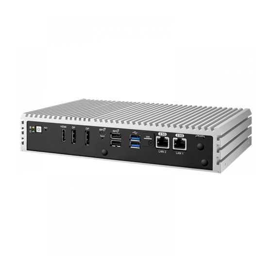
Page 19: Front Panel I/O Functions
USB, HDMI, DisplayPort, LAN Jack and any additional storage, are placed on the front panel. 2.2.1 Reset Tact Switch It is a hardware reset switch. Please use this switch to reset ECS-4700 without power off. Press the Reset Switch for a few seconds, and then reset will be enabled. - Page 20 HDD LED/ Yellow : A hard disk/M.2 M key LED. If the LED is on, it indicates that ECS-4700 storage is functional. If it is off, it indicates that the system’s storage is not functional. If it is flashing, it indicates data access activities.
- Page 21 There are 2 USB 3.2 connections available supporting up to 10GB per second data rate in the front side of ECS-4700 series. It also compliant with the requirements of Super Speed (SS), high speed (HS), full speed (FS) and low speed (LS).
- Page 22 M2B_CN1 M2E_CN1 M2B_SIM1 GETTING TO KNOW YOUR ECS-4500...
- Page 23 DisplayPort 1.4a : Up to 3840 x 2160 @ 60Hz by USB Type-C in the front side of ECS-4700 series. 2.2.10 Ethernet Port There are two 8-pin RJ-45 jacks supporting 10/100/1000/2500 Mbps Ethernet connections on the front side of ECS-4700. LAN1 and LAN 2 is powered by Intel I226 Ethernet engine. LAN Chip Function...
- Page 24 Yellow Yellow Yellow Yellow Yellow 2.2.11 SSD/HDD Tray There are 2 front-access 2.5” SSD/HDD trays in the front side of ECS-4700- PoER series. Just trigger to open the SSD/HDD tray, up to 4TB is available. GETTING TO KNOW YOUR ECS-4500...
-
Page 25: Rear Panel I/O And Functions
2.3 Rear Panel I/O and Functions 2.3.1 Power Terminal Block ECS-4700 supports dual 9V to 50V DC power input by terminal block in the rear side. In normal power operation, power LED lightens in solid green. Pin No. Definition Pin No. - Page 26 2.3.3 Isolated DIO There is a 16-bit (8-bit DI, 8-bit DO) connectors in the Isolated Isolated rear side. DI/DO support NPN(sink) and PNP(Source) mode, Each DI channel is equipped with a photocouper for isolated protection. Each DO with isolator chip, Config by a Jumper for each DIO connector.
- Page 27 DO Signal circuit in SINK mode (NPN) Source (PNP) DIO_VDC (20) LOAD 7.2K ISOLATION 6-40V (11) (300mA) 1.5K GNDI GNDO GNDO (10.19) Internal Circuit External Device GNDO DO Signal circuit in source mode (PNp) ©Vecow ECS-4500 User Manual GETTING TO KNOW YOUR ECS-4500...
- Page 28 2.3.4 Serial Port COM COM1 COM2 Serial port 1 to 4 (COM 1 to 4) can be configured for RS-232, RS-422, or RS- 485 with auto flow control communication. The default definition is RS-232. If you want to change to RS-422 or RS-485, you can find the setting in BIOS. BIOS Setting Function RS-232...
- Page 29 2.3.5 PoE (Power over Ethernet) Ports There are 4 RJ45 connectors in the rear side of ECS-4700. It supports IEEE 802.3at (PoE+) Power over Ethernet (PoE) connection delivering up to 25W/54V per port and 1000BASE-T gigabit data signals over standard Ethernet Cat 5/Cat 6 cable.(Remind : PoE power budget supports up to 25.5W/each, total 35W.)
- Page 30 Green Off: Non PD 2.3.6 Audio Jack There are 2 audio connectors, Mic-in and Line-out, in the front side of ECS-4700 Onboard Realtek ALC888 audio codec supports 7.1 channel HD audio and fully complies with Intel® High Definition Audio (Azalia) specifications.
-
Page 31: Main Board Expansion Connectors
2.4 Main Board Expansion Connectors 2.4.1 Top View of ECS-4700 Main Board With Connector Location CN_LAN1 CN_LAN2 IGN1 COM1 COM2 SYS_FAN1 AUDIO1 M2B_CN1 M2E_CN1 J5_IGN JPOE_PWR1 JUSBPWR1 JINGMODE1 J7_POE CN_DP2 CN_DP1 HDMI1 LAN1 LAN2 CN_USB3X1 M2B_SIM1 PWR_BTN1 CN_TYPEC1 RST_SW1 USB2_1 LED1 2.4.2 Bottom View of ECS-4700 Main Board with Connector Location... - Page 32 2.4.3 J1 J2 : Serial Port cable Connector Location Definition COM3 COM4 Layout Pin No. Description 2.4.4 J4:Internal USB 2.0 GETTING TO KNOW YOUR ECS-4500...
- Page 33 The ECS-4700 main board provides maxima two expansion USB ports. The USB interface supports 480Mbps transfer rate which comply with high speed USB specification Rev. 2.0. The J4 interface is accessed through one 10-pin JST 1.0mm connector(selection option). You will need an adapter cable if you use a standard USB connector.
- Page 34 2.4.6 J6:VCORE FW Programming Header Layout Pin No. Description SDA_P SCL_P 2.4.7 J7_POE:POE FW Programming Header J7_POE Layout Pin No. Description POE_MCU_RST# +3V_ISO POE_MCU_PRG GETTING TO KNOW YOUR ECS-4500...
- Page 35 2.4.8 J8 : ESPI Port 80 Header The system’s provide a ESPI Port 80 Header for Debug Card. Layout Pin No. Description +V3.3S Port 80_ESPI_CS# Port 80_ESPI_IO0 Port 80_ESPI_IO1 Port 80_ESPI_IO2 Port 80_ESPI_IO3 Port 80_ESPI_CLK RST 80_ESPI_RST# ©Vecow ECS-4500 User Manual GETTING TO KNOW YOUR ECS-4500...
- Page 36 2.4.9 CPU_FAN1 ,SYS_FAN1: FAN Header SYS_FAN1 CPU_FAN1 Fan power connector supports for additional thermal requirements. The pin assignments of CPU_FAN1/SYS_FAN1 are listed in the following table. CPU_ FAN1 header soldering by customized request. Layout Pin No. Definition Pin No. Definition +12V (1.5A max) Fan speed sensor Fan PWM...
- Page 37 There are 2 DDR5 channel onboard, support DDR5 4800, max 64GB, each channel 32GB. Slot Description DDR5_A2 DDR5 Channel A DDR5_A1 DDR5 Channel B 2.4.11 CN3: BIOS Socket If the BIOS needs to be changed, please contact the Vecow RMA service team. ©Vecow ECS-4500 User Manual GETTING TO KNOW YOUR ECS-4500...
- Page 38 2.4.12 SATA1, SATA2 : SATA III Connector There are 2 onboard high performance Serial ATA III (SATA III) on ECS-4700. It supports higher storage capacity with less cabling effort and smaller required space. The pin assignments of SATA1 and SATA2 are listed in the following table : SATA1/SATA2 Pin No.
- Page 39 2.4.14 BAT1: RTC Battery BAT1 The ECS-4700's real-time clock is powered by a lithium battery. It is equipped with Panasonic BR2032 190mAh lithium battery. It is recommended that you not replace the lithium battery on your own, but if the battery needs to be changed, please contact the Vecow RMA service team.
- Page 40 Pin No. Function Pin No. Function Ground 3.3V Ground 3.3V 3.3V SIM DETECT Ground REFCLKp REFCLKn PEWAKE# Ground CLKREQ# PETp0/SATA-A+ PERST# PETn0/SATA-A- Ground PERp0/SATA-B- PERn0/SATA-B+ Ground PETp1/USB3.1-TX+ DEVSLP PETn1/USB3.1-TX- UIM-PWR Ground UIM-DATA PERp1/USB3.1-RX+ UIM-CLK PERn1/USB3.1-RX- UIM-RESET Ground GETTING TO KNOW YOUR ECS-4500...
- Page 41 2.4.16 M.2 KEY-E (M2E_CN1) M2E_CN1 M.2 KEY E: USB2.0/PCIex1 M.2 key E connector is suitable for applications that use wireless connectivity including Wi-Fi, Bluetooth, NFC of GNSS. Module card types include 2230. ©Vecow ECS-4500 User Manual GETTING TO KNOW YOUR ECS-4500...
- Page 42 Pin No. Function Pin No. Function Ground 3.3V 3.3V Ground PEWAKE1# Ground ALERT I2C_CLK Ground I2C_DATA PEWAKE0# CLKREQ0# Ground PERST0# REFCLKn0 REFCLKp0 Ground PERn0 PERp0 Ground PETn0 DEVSLP PETp0 Ground Mechanical Key Ground Ground GETTING TO KNOW YOUR ECS-4500...
- Page 43 M.2 key M connector is suitable for applications that use Host I/Fs supported by either PCIe Module card types include 2280 (Only Support PCIEx4) Pin No. Function Pin No. Function Ground Ground 3.3V Ground 3.3V PEDET 3.3V Ground Mechanical Key Ground REFCLKp REFCLKn PEWAKE# ©Vecow ECS-4500 User Manual GETTING TO KNOW YOUR ECS-4500...
- Page 44 Ground CLKREQ# PETp0/SATA_A+ PERST# PETn0/SATA_A- Ground PERp0/SATA_B- PERn0/SATA_B+ Ground PETp1 DEVSLP PETn1 Ground PERp1 PERn1 Ground PETp2 PETn2 Ground PERp2 PERn2 3.3V Ground 3.3V PETp3 3.3V PETn3 3.3V Ground LED1# PERp3 PERn3 Ground 3.3V Ground 3.3V GETTING TO KNOW YOUR ECS-4500...
-
Page 45: Main Board Jumper & Dip Switch Settings
RST_SW1 USB2_1 LED1 The figure below is the top view of ECS-4700 board, and it shows the location of the jumpers and the switches. You may configure your card to match the needs of your application by setting jumpers. A jumper is a metal bridge used to close an electric circuit. It consists of two metal pins and a small metal clip (often protected by a plastic cover) that slides over the pins to connect them. - Page 46 2.5.2 USB Power Jumper (JUSBPWR1) JUSBPWR1 Layout Pin No. Description Supported Wake Up(Default) Non Wake Up support 2.5.3 PoE Power ON Select(JPOE_PWR1) JPOE_PWR1 Layout Pin No. Description PoE power on at standby power ready PoE power on after system power on(Default) No Jumper Disable PoE power 2.5.4 HDA_SDO1(JP2)
- Page 47 DCD / RXD Termination 120R Disable(default) 1(ON) DCD / RXD Termination 120R enable COM3 1(OFF) DCD / RXD Termination 120R Disable(default) 2(ON) DCD / RXD Termination 120R enable COM4 2(OFF) DCD / RXD Termination 120R Disable(default) ©Vecow ECS-4500 User Manual GETTING TO KNOW YOUR ECS-4500...
-
Page 48: Ignition Control
The built-in MCU monitors the ignition signal and turns on/ off the system according to pre-defined on/off delay periods. 2.6.1 Adjust Ignition Control Modes ECS-4700 series provides 16 modes of different power on/ off delay periods adjustable via rotary switch. The default rotary switch is set to 0 in ATX/AT power mode. - Page 49 5 seconds 30 minutes 5 seconds 1 hour 10 seconds 2 hours 10 seconds 4 hours 10 seconds 6 hours 10 seconds 8 hours 10 seconds 12 hours 10 seconds 24 hours ©Vecow ECS-4500 User Manual GETTING TO KNOW YOUR ECS-4500...
- Page 50 1. DC power source and IGN share the same ground. 2. ECS-4700 supports 9V to 50V wide range DC power input in ATX/ AT mode. In Ignition mode, the input voltage is fixed to 12V/ 24V for car battery scenario.
-
Page 51: Chapter 3 System Setup
SYSTEM SETUP 3.1 How to Open Your ECS-4700 Step 1 Remove six Flat-M3x5L screws . Step 2 Finish. ©Vecow ECS-4500 User Manual HARDWARE INSTALLATION... -
Page 52: Installing Ddr5 So-Dimm Modules
3.2 Installing DDR5 SO-DIMM Modules Step 1 Install DDR5 into SO-DIMM slot. (Only install one DDR5, it is recommend to install on DDR5_A1) Step 2 Make sure the RAM module is locked by the memory slot. HARDWARE INSTALLATION... - Page 53 Step 3 Reomve thermal pad flim on DDR5 Cu Plate. Step 4 Install DDR5 Cu Plate on SO-DIMM and fasten two PH-M3x4L screws. ©Vecow ECS-4500 User Manual HARDWARE INSTALLATION...
-
Page 54: Installing Nano Pcie Card
3.3 Installing Nano PCIe Card Step 1 Remove one Flat-M3x5L screw on SIM cover at front panel. Step 2 Before Inserting SIM Card, make sure the system power is not plugged. Step 3 Insert SIM card and push to lock. HARDWARE INSTALLATION... -
Page 55: Installing Ssd/ Hdd
3.4 Installing SSD/ HDD 3.4.1 ECS-4700-PoE/2G Step 1 Remove ten Flat-M3x5L screws. Step 2 Fix one SSD/HDD on the tray with four I-M3x3 screws . ©Vecow ECS-4500 User Manual HARDWARE INSTALLATION... - Page 56 3.4.2 ECS-4700-PoER Step 1 SSD/HDD Tray. Step 2 Fix one SSD/HDD on the tray with four Flat-M3x4L screws. HARDWARE INSTALLATION...
- Page 57 Step 3 Put the SSD/HDD tray and then clockwisely fasten the locks. ©Vecow ECS-4500 User Manual HARDWARE INSTALLATION...
-
Page 58: Installing
3.5 Installing M.2 3.5.1 M.2 Key E 2230 / Key B 2280 / Key M 2280 Step 1 Install M.2 Key E 2230/ Key B 2280 / Key M 2280 into slot and fasten PH M3x4L screw. Step 2 Reomve thermal pad flim on M.2 Key M Cu Plate. HARDWARE INSTALLATION... - Page 59 Step 3 Install M.2 Key M Cu Plate and fasten two PH-M3x4L screws. 3.5.2 M.2 Key B 3042 Step 1 Install M.2 Key B 3042 on extend bracket and fasten one PH-M3x4L screw. ©Vecow ECS-4500 User Manual HARDWARE INSTALLATION...
- Page 60 Step 2 Install module into slot and fasten PH M3x4L screw. 3.5.3 M.2 Key B 3052 Step 1 Break off excess extender bracket. HARDWARE INSTALLATION...
- Page 61 Step 2 Install M.2 Key B 3052 on extend bracket and fasten one PH-M3x4L screw. Step 3 Install module into slot and fasten PH M3x4L screw. ©Vecow ECS-4500 User Manual HARDWARE INSTALLATION...
-
Page 62: Installing Antenna Cable
3.6 Installing Antenna Cable Step 1 Remove the rubber corks on the panel. Step 2 Put antenna cable connector into the hole on panel. Step 3 Fasten washer on the antenna cable connector. HARDWARE INSTALLATION... -
Page 63: Mounting Your Ecs-4700
3.7 Mounting Your ECS-4700 3.7.1 Wall Mount Bracket Step 1 Ensure the screw holes on the right and left side of upper case match the ones on ECS-4700.Fasten four Hexagon #6-32x6L screws. Step 2 Finish. ©Vecow ECS-4500 User Manual HARDWARE INSTALLATION... - Page 64 3.7.2 VESA Mount (75mm x 75mm & 100mm x 100mm) Step 1 Ensure the screw holes on the right and left side of upper case match the ones on ECS-4700.Fasten four Hexagon #6-32x6L screws. Step 2 Finish. HARDWARE INSTALLATION...
- Page 65 3.7.3 Din Rail Kit Step 1 Ensure the screw holes on the right and left side of upper case match the ones on ECS-4700.Fasten four Hexagon #6-32x6L screws. Step 2 Finish. ©Vecow ECS-4500 User Manual HARDWARE INSTALLATION...
- Page 66 BIOS SETUP 4.1 BIOS SETUP Figure 4-1: Entering Setup Screen BIOS provides an interface for users to check and change system configuration. The BIOS setup program is accessed by pressing the <Del> key when POST display output is shown. BIOS AND DRIVER SETTING...
- Page 67 Set the Date. Use <Tab> to switch between Date elements. Default Ranges: Year: 1998-9999 Months: 1-12 Days: Dependent on month Range of Years may vary. System Time Set the Time. Use <Tab> to switch between Time elements. ©Vecow ECS-4500 User Manual BIOS AND DRIVER SETTING...
- Page 68 4.3 Advanced Function Figure 4-3: BIOS Advanced Function Select advanced tab to enter advanced BIOS setup options such as CPU configuration, ACPI settings, and Super IO configuration. 4.3.1 CPU Configuration Figure 4-3-1: CPU Configuration Efficient-core Information Displays the E-core Information Performance-core Information Displays the P-core Information Hardware Prefetcher...
- Page 69 Cores and E-cores are looked at together. When both are {0,0}, Pcode will enable all cores. Hyper-Threading Enable or Disable Hyper-Threading Technology. Enable/Disable AES (Advanced Encryption Standard) 4.3.2 Power & Performance Figure 4-3-2: Power & Performance ©Vecow ECS-4500 User Manual BIOS AND DRIVER SETTING...
- Page 70 4.3.2.1 Power & Performance Figure 4-3-2-1: CPU - Power Management Control Turbo Mode Enable/Disable processor Turbo Mode (requires EMTTM enabled too). AUTO means enabled. View/Configure Turbo Options View/Configure Turbo Options 4.3.3 PCH-FW Configuration Figure 4 3-3: PCH-FW Configuration 4.3.3.1 PTT Configuration Figure 4-3-3-1: PTT Configuration TPM Device Selection Selects TPM device: PTT or dTPM.
- Page 71 Enables or Disables System ability to Hibernate (OS/S4 Sleep State). This option may not be effective with some operating systems. ACPI Sleep State Select the highest ACPI sleep state the system will enter when the SUSPEND button is pressed. ©Vecow ECS-4500 User Manual BIOS AND DRIVER SETTING...
- Page 72 4.3.6 IT8786 Super IO Configuration Figure 4-3-6: IT8786 Super IO Configuration 4.3.6.1 Serial Port X Configuration Figure 4-3-6-1: Serial Port X Configuration Serial Port Enable or Disable Serial Port (COM) Device Mode Select Device Mode. PPS Mode Enable or Disable PPS. High Speed Mode (Port 1 only) Enable or Disable Serial Port High Speed.
- Page 73 Fan full speed temperature limit Fan will full speed when temperature higher than this limit Fan start PWM Fan will start with this PWM value. Manual PWM Setting Fan will work with this Manual PWM Value ©Vecow ECS-4500 User Manual BIOS AND DRIVER SETTING...
- Page 74 4.3.8 Network Stack Configuration Figure 4 3-8: Network Stack Configuration Network Stack Enable/Disable UEFI Network Stack. IPv4 PXE Support Enable/Disable IPv4 PXE boot support. If disabled, IPv4 PXE boot support will not be available. IPv4 HTTP Support Enable/Disable IPv4 HTTP boot support. If disabled, IPv4 HTTP boot support will not be available.
- Page 75 4.4.1 System Agent (SA) Configuration Figure 4-4-1: System Agent (SA) Configuration Above 4GB MMIO BIOS assignment Enable/Disable above 4GB MemoryMappedIO BIOS assignment. This is enabled automatically when Aperture Size is set to 2048MB. ©Vecow ECS-4500 User Manual BIOS AND DRIVER SETTING...
- Page 76 4.4.1.1 Memory Configuration Figure 4-4-1-1: Memory Configuration Maximum Memory Frequency Maximum Memory Frequency Selections in Mhz. Max TOLUD Maximum Value of TOLUD. Dynamic assignment would adjust TOLUD automatically based on largest MMIO length of installed graphic controller BIOS AND DRIVER SETTING...
- Page 77 DVMT Pre-Allocated Select DVMT 5.0 Pre-Allocated (Fixed) Graphics Memory size used by the Internal Graphics Device. DVMT Total Gfx Mem Select DVMT5.0 Total Graphic Memory size used by the Internal Graphics Device. ©Vecow ECS-4500 User Manual BIOS AND DRIVER SETTING...
- Page 78 4.4.1.3 VMD setup menu Figure 4-4-1-3: VMD setup menu Enable VMD controller Enable/Disable to VMD controller. 4.4.1.4. PCI Express Configuration (SA) Figure 4-4-1-4: PCI Express Configuration (SA) PCI Express Root Port X PCI Express Root Port Settings. 4.4.1.4.1 PCI Express Root Port X (SA) Figure 4-4-1-4-1: PCI Express Root Port X (SA) PCI Express Root Port X Control the PCI Express Root Port.
- Page 79 Figure 4-4-2-1: PCI Express Configuration (PCH-IO) 4.4.2.2 PCI Express Root Port X (PCH-IO) Figure 4-4-2-2: PCI Express Root Port X (PCH-IO) PCI Express Root Port X Control the PCI Express Root Port. PCIe Speed Configure PCIe Speed. ©Vecow ECS-4500 User Manual BIOS AND DRIVER SETTING...
- Page 80 4.4.2.3 SATA Configuration Figure 4-4-2-3: SATA Configuration SATA Controller(s) Enable / Disable SATA Device. 4.4.3 Module Management Figure 4-4-3: Module Management Specific device workaround Workaround for specific device. Delay Time 0~255 (second). M2B_CN1 Type Select M2B_CN1 Type. BIOS AND DRIVER SETTING...
- Page 81 Voltage Guard enable or disable, only effect on Ignition mode. Voltage Guard Lower limit value Voltage Guard lower limit value setting. Range: 9v ~ 40v. Voltage Guard higher limit value Voltage Guard Higher limit value setting. Range: 15v ~ 55v. ©Vecow ECS-4500 User Manual BIOS AND DRIVER SETTING...
- Page 82 4.5 Security Functions Figure 4-5: Security Functions Administrator Password Set administrator password. 4.5.1 HDD Security Configuration Figure 4-5-1: HDD Security Settings BIOS AND DRIVER SETTING...
- Page 83 Force System to User Mode. Install factory default Secure Boot key databases Reset To Setup Mode Delete all Secure Boot key databases from NVRAM Key Management Enables expert users to modify Secure Boot Policy variables without variable authentication. ©Vecow ECS-4500 User Manual BIOS AND DRIVER SETTING...
- Page 84 4.6 Boot Function Figure 4-6: Boot Function Setup Prompt Timeout Number of seconds to wait for setup activation key. 65535(0xFFFF) means indefinite waiting. Bootup NumLock State Select the keyboard NumLock state. Quiet Boot Enables or disables Quiet Boot option. Boot Option Priorities Sets the system boot order.
- Page 85 Save Changes and Reset Reset the system after saving the changes. Discard Changes and Reset Reset system setup without saving any changes. Restore Defaults Restore/Load Default values for all the setup options. ©Vecow ECS-4500 User Manual BIOS AND DRIVER SETTING...
- Page 86 APPENDIX A : Isolated DIO Guide A.1 Function Description The ECS-4700 series offers a 16-bit DIO (8-DI/ 8-DO) 20-pin terminal block connector. Each bit of DI and DO equipped with a photo-coupler for isolated protection. All IO pins are fixed by Hardware design and cannot change in/out direction in runtime process.
- Page 87 .Header folder include head file for software developer or System Integration. .Manual folder include API description. .Sample folder include sample program, driver library, and API library for Windows/Linux .Source folder include sample program source code that compile on Visual Studio 2008/Ubuntu18.04. Appendix A ©Vecow ECS-4500 User Manual...
- Page 88 A.4 Sample Execute demo tool. Windows Linux Sample, as shown below : Vecow_DIO Vecow_DIO_loopback Vecow_WDT POE Default Address:0x44(8bit),0x22(7bit) Appendix A...
- Page 89 APPENDIX B : Software Functions B.1 Driver API Guide In Header folder, Vecow.h and VecowLinux.h contain usabled API for Windows/Linux. BOOL initial_SIO(BYTE Isolate_Type, BYTE DIO_NPN) Initial machine for IO and watch dogtimer. Isolate_Type: DIO type. • 1: Isolated DIO; 0: Non-Isolated DIO(GPIO).
- Page 90 BOOL set_IO1_configuration(BYTE Iso, BYTE DI_mode, BYTE DO_mode, WORD Mask) BOOL set_IO2_configuration(BYTE Iso, BYTE DI_mode, BYTE DO_mode, WORD Mask) Set DIO configuration. Isolate_Type: DIO type. • 1: Isolated DIO; 0: Non-Isolated DIO(GPIO). DI_mode ([7:0]): DI type, pin setting by hexadecimal bitmask only for Isolated DIO. •...
- Page 91 • Range: 1~6. mode: Usable COMPORT number. • 0: RS232 mode; 1: RS422-5Wire mode. 2: RS422-9Wire mode; 4: RS485 mode. 4: Loopback mode. term: Termination enable for RS422/RS485 mode. • 1: Enable; 0: Disable. Appendix C ©Vecow ECS-4500 User Manual...
- Page 92 Return: TRUE (1): Success. FALSE (0): Fail (Initial error or hardware problem). BOOL get_COMPORT_mode(BYTE port, BYTE *mode, BYTE term) Get COMPORT mode. port: which port get. • Range: 1~6. mode: Usable COMPORT number. • 0: RS232 mode; 1: RS422-5Wire mode. 2: RS422-9Wire mode;...
- Page 93 Mode : Manual/Auto • 0: Manual 1: Auto POE ([3:0]): POE state • 1: On; 0: Off Return: TRUE (1): Success; FALSE (0): Fail (Initial error, or out of range error, or hardware problem) Appendix C ©Vecow ECS-4500 User Manual...
- Page 94 APPENDIX C : RAID Functions C.1.1 VMD Controller for RAID Please set Enable VMD controller as Enabled on BIOS menu. Chipset → System Agent (SA) Configuration → Enable VMD controller → Enabled → Save Changes and Reset. C.1.2 UEFI Mode for RAID 1.
- Page 95 2. Select Create RAID Volume on BIOS menu. 3. Select disks to create RAID Volume then Save Changes and Reset to install OS with EFI mode. Appendix C ©Vecow ECS-4500 User Manual...
- Page 96 C.2 OS Installation The system is featured with one M.2 key M for NVME, one mSATA slot, and including two internal SATA. We used SATA for Windows 10 OS installation as an example. Note: ECX-3100 PEG, ECX-3200 PEG, ECX-3200MX PEG are equipped with 2 SATA. ECX-3400 PEG, ECX-3600 PEG, ECX-3800 PEG are equipped with 4 SATA.
- Page 97 Let’s take RAID 1 as an example, select ”RAID 1”. C.7 Disk Management : Partition the Disk After RAID 1 volume is created, you can see the figure of SATA device allocation. You will find"Volume_0000" in SATA device at BIOS menu. Appendix C ©Vecow ECS-4500 User Manual...
- Page 98 To start disk management tool, select"initialize disk". Then add"Logical Device" for Windows access. C.8 If One SATA HDD on RAID Volume is Out-of-use After RAID 1 volume is created, you can see the figure of SATA device allocation. HDD CAUTION Sign Appendix C...
- Page 99 A warning will pop-up to ask you if the disk is not a member of the original RAID volume. If you press"Rebuild", it will replace the broken SATA HDD to the last SATA HDD of RAID volume. Appendix C ©Vecow ECS-4500 User Manual...
- Page 100 APPENDIX D : Power Consumption Testing Board ECS-4700 32GB X 2 USB-1 USB Micsoft Wired Keyboard 600 USB-2 USB Mouse HP G1K28AA USB-3 USB Flash ADATA 3.0 8GB USB-4 USB Flash ADATA 3.0 8GB SATA 0 Transcend SATA SSD420 128GB...
- Page 101 Run 100% CPU Power usage with 2D usage with 3D Input Current Consumption Current Consumption i5-1345UE 3.3933 30.54W 3.494 31.45W i5-1345UE 2.548A 30.58W 2.569A 30.83W i5-1345UE 1.400A 33.60W 1.345A 32.28W i5-1345UE 0.721A 36.03W 0.701A 35.06W Appendix D ©Vecow ECS-4500 User Manual...
- Page 102 D.2 Intel® Core™ i5-1345UE 1.40 GHz (12M Cache, up to 4.60 GHz ) Power on and boot to Win 10 64-bit (with turbo boost technology) Power on and boot to Win 10 (64-bit) Standby Mode idle status CPU Power Sleep Mode usage less 3% Input Current...
- Page 103 Run 100% CPU Power usage with 2D usage with 3D Input Current Consumption Current Consumption i7-1365UE 3.458A 31.12W 3.685A 33.17W i7-1365UE 2.685A 32.22W 2.765A 33.18W i7-1365UE 1.410A 33.84W 1.435A 34.44W i7-1365UE 0.693A 34.65W 0.713A 35.64W Appendix D ©Vecow ECS-4500 User Manual...
- Page 104 D.4 Intel® Core™ i7-1365UE 1.70 GHz (18M Cache, up to 5.00 GHz ) Power on and boot to Win 10 64-bit (with turbo boost technology) Power on and boot to Win 10 (64-bit) Standby Mode idle status CPU Power Sleep Mode usage less 3% Input Current...
- Page 105 PASS PASS *1(Socket 1) PASS PASS PASS *1(Socket 2) PASS PASS PASS Brand Info Test Temp.(Celsius) 25ºC SLLINK 32G DDR5 J5BGSH2G8A4FC 25ºC 4800 SO-DIMM 25ºC 25ºC SMART 32G DDR5 SR4G6SO5285-SB 25ºC 4800 SO-DIMM 25ºC Appendix E ©Vecow ECS-4500 User Manual...
- Page 106 512GB Kingston SA2000MB 250GB 970 EVO PLUS 250GB MZ-V7S250 SAMSUNG PCIe 980 EVO PRO 250GB MZ-V8P250BW 760P INTEL 128GB SSDPEKKW128G8 SMART FDMP8960GTCXA111 960GB Transcend TS512GMTE460T 512GB ** If more help is needed, please contact Vecow technical support ** Appendix E...
- Page 107 No part of this publication may be reproduced in any form or by any means, electric, photocopying, or recording, without prior authorization from the publisher. The rights of all the brand names, product names, and trademarks belong to their respective owners. © Vecow Co., Ltd. 2024. All rights reserved.
Need help?
Do you have a question about the ECS-4700 and is the answer not in the manual?
Questions and answers