Table of Contents
Advertisement
Quick Links
M
3
M
3
F
o
r
i
n
d
F
o
r
i
n
d
Metro
80 impasse des chapotines
ZAE Chez Merlin
F-74420 St-André de Boëge
France
u
c
t
i
v
e
,
1
V
p
u
c
t
i
v
e
,
1
V
p
USER'S MANUAL
p
a
n
d
T
T
L
p
p
a
n
d
T
T
L
Firmware 3.0
r
o
b
e
s
p
r
o
b
e
s
+33 (0) 450 39 08 49
Fax
+33 (0) 450 39 08 33
web
www.metro-fr.com
E-mail info@metro-fr.com
Advertisement
Table of Contents

Related Manuals for Metro DataVac M3

Summary of Contents for Metro DataVac M3
- Page 1 USER’S MANUAL Firmware 3.0 +33 (0) 450 39 08 49 Metro +33 (0) 450 39 08 33 80 impasse des chapotines www.metro-fr.com ZAE Chez Merlin F-74420 St-André de Boëge France E-mail info@metro-fr.com...
-
Page 2: Table Of Contents
1. TABLE OF CONTENTS TABLE OF CONTENTS ___________________________________________ 2 FOREWORDS __________________________________________________ 4 INTRODUCTION ________________________________________________ 5 3.1. PRODUCT PRESENTATION ................ 5 3.2. VERSIONS ....................5 3.3. CHARACTERISTICS ..................6 3.3.1. - Page 3 RS232 COMMUNICATION _______________________________________ 63 8.1. COMMANDS ....................63 8.1.1. GENERALITIES ..................63 8.1.2. COMMAND LIST .................. 64 8.1.2.1. WINDOW PART ................64 8.1.2.2. WINDOW DISPLAY ................65 8.1.2.3. WINDOW CONFIGURATION ............
-
Page 4: Forewords
2. FOREWORDS ONE YEAR LIMITED GUARANTEE MANUFACTURER'S RESPONSIBILITY SPARE PARTS AND LABOUR. The manufacturer commits himself to pay for repair or replacement costs (labour costs included) during a period of one year as from the date the guarantee came into force. -
Page 5: Introduction
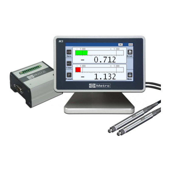
(Max, Min, Max-Min…) The M3 can be connected to a PC thanks to its RS232 or USB connection. A footswitch can be connected in order to transfer measurements. 3.2. VERSIONS... -
Page 6: Characteristics
Heidenhain with a 11µA or 1Vpp output 1301T 2 inductive probe with a Tesa compatibility 1301M 2 x inductive probe from Mahr 3.3. CHARACTERISTICS 3.3.1. Main technical characteristics TFT colour touch screen display 4,3’’, resolution 480x272. Static or dynamic measurements (Max, Min, Max-Min, Average, Median) ... -
Page 7: Dimension And Installation
3.3.2. Dimension and installation The M3 is fitted with 4 thread M5 allowing to attach it. To access to these thread it is necessary to remove the 4 antiskid plastic parts. Remove the antiskid parts to attach it on the table It is also possible to panel mount the display, with the accessory ref ACS-AFF-001. -
Page 8: Contents Of The Packaging
- 1 M3 display mounted on a stand - 1 USB cable, (length =1.8m) for power supply and/or data transfer - 1 USB main adaptor for the display power supply. The M3 can also be powered by a computer when connected to it with the USB. - Page 9 The module is also fitted with 6 inputs allowing to remote control the display. This MB-RL module is wired exactly like the #24136 optional board for Monocote displays. It allows then to replace a Monocote by a M3 without changing the machine/plc wiring. Page 9...
- Page 10 81213- M-Bus cable for M3 (TTL or 1Vpp or 11µA version) : This cable allows to connect the compatible M-Bus modules on a M3 display unit. Length 1.5m. The cable is fitted with a M8 conenctor on the display side.
- Page 11 Heidenhain M23/11µA to D-SUB 15 adapter for M3 84100 11µA/1Vpp : This cable allows to connect 1 Heidenhain probe like MT12 or MT25 with the round M23 connector on a M3 (ref 13020) display. 45160 RS232 cable This cable allows to connect a M3 display to a computer.
- Page 12 45173 RS232/USB cable converter : This cable allows a M3 display to communicate with a computer. It creates a virtual COM port on the computer. It is delivered with a driver on a CD. 24061 This cable allows to connect 1 Mitutoyo LG probe on a M3 (ref 13000) display.
-
Page 13: Connectors
This power supply is not available on the Mahr and Marposs devices Note: Metro provides different version for M3 for inductive probes : for Tesa compatible probes, for Mahr, for Metro or for Marposs. Each of these probes has the same DIN-5 connector but is different internally. -
Page 14: Version For Incremental Probes And Encoders
Important Note : 2 versions of this unit are available. For sinewave 11µA and 1Vpp probes (ref 13020), and for TTL probes (ref 13000). Please make sure that you are using the right version of M3 depending on the probe you use. -
Page 15: Rs232 Communication Port
3.3.6. RS232 communication port The M3 is fitted with a RS232 port. It allows linking the M3 to PC or an external system. The configuration is as following 9600 bauds, 8 bits, 1 stop bit, no parity CONNECTOR PINOUT It is fitted with a SUBD 9 pins female connector. -
Page 16: The 24Vdc Connector
3.3.8. The 24VDC connector It is advised to use this power supply when the M3 is panel mounted. Using this power supply instead of the mini-USB will deactivate the ON-OFF switch. Therefore, when the M3 is powered, it will start automatically. -
Page 17: Graphical Interface
BMP file (screenshot) in the USB stick. 4. GRAPHICAL INTERFACE The graphical interface of your M3 has been designed to be easy to use and intuitive. This section gives you a preview of the different screens and commands available 4.1. - Page 18 The second part (measuring screen) is called by pressing the button 2. This part allows to see the measurement result and to use them. The M3 starts on this screen. For reaching the configuration screens, press on the button...
-
Page 19: Generalities
4.2. GENERALITIES The following information can be seen on the upper part of the screen. Name of the active Static or Unit: mm, µm, inch part reference and dynamic (Max, or decimal degree formula. Here Part 1 Min etc…) with Channel 1 Inside or outside measurement... - Page 20 In the same way it is also possible to input a manufacturer order either with an RS232 command, or by scanning a QR code : Manufacturing order USB logo appear when number entered with a USB stick or a QR RS232 or QR code code reader has been plugged.
-
Page 21: Configuration Windows
4.3. CONFIGURATION WINDOWS Configuration windows opens after pressing on the icons of the icon desktop Example of configuration windows Data are typed by different ways and are saved after validating while quitting the window. Here after are the different ways to input data: ... -
Page 22: Virtual Keyboard
4.4. VIRTUAL KEYBOARD Erase Quit without taking into account the modification Quit and save the modification Page 22... -
Page 23: Configuration Of The Device And The Measure
If you are on the measuring screen, you can reach the icon desktop by clinking on the button. Your M3 can be entirely configured (language, communication etc…) from this window. The measure (tolerances, characteristics etc…) is also configured from this window. -
Page 24: Definition
5.1. DEFINITION After clicking on this icon, the bellow window appears: It gives the possibility to define the tolerances, the master, and the nominal value of the characteristic, the resolution of each of the 2 available measurement configurations. This window is divided in 2 parts for the configuration of the 2 measurement configurations. -
Page 25: Part 1
5.1.1. Part 1 Static = direct reading or dynamic: Max, Min, Max- Min, Average or Median For measuring internal or external diameters. Choice of the calculation formula: C(1) C(2) C(1) + C(2) C(1) - C(2) -C(1) ... - Page 26 Resolution 000.000 = micron 00.0000 = 0.1 micron Unit mm : millimeters In : inches Um = Microns Deg = decimal degrees (automatic choice when the formula is set as Taper) DMS = Degrees / Minutes / Seconds Mode Static = direct reading: The display is refreshed together with the probe is moving. Dynamic : The following mode starts after pressing on the “clear”...
- Page 27 On this table 3 points, 2 points are fixes and the third one moves to constrain the part and measure its diameter For this kind of measurement, a new option appears: “Tip diameter” The size (diameter) of the tip must be written here in order to calculate correctly the diameters of the part...
- Page 28 To measure the angle, 2 probes are compulsory, and must be placed to different diameter of the cone. The distance between each diameter has to be entered on the parameters. When the “cone measure” is used, the choice of the unit of measurement disappears, and is fixed to “degree”...
-
Page 29: Part 2
way to rework the characteristics of the bore to make it fit in the tolerance interval. However, if the bore is too small, it can still be increased, and then the part could fit in the tolerance interval. In this case, the internal diameter is used, as on the pictures bellow. -
Page 30: Part 3, Class
5.1.3. Part 3, class This screen allows to set up a sorting of the part according to their size. Up to 16 class can be programed Choice of the number of class Choice of the color for each class The limit defined for each class are selected by default but they can be changed by the user The class has an important utility, because it allows the user to sort the parts... - Page 31 Grey color because of the class parameters. Page 31...
-
Page 32: Part 4, Control Limit
5.1.4. Part 4, control limit This screen allows to display or not the control limits (warnings) and to define them. Control limits are warnings that inform the user if the measure becomes too close to the tolerances limits. (Yellow colour on the bargraph) This part is hidden if «... -
Page 33: Display
5.2. DISPLAY After clicking on this button, the below window appears. This window allows to define if 1 or 2 measure are displayed on the screen and on which format (needle = galva, horiziontal bargraph or value only). The auto-switch function allows to call the corresponding program by a simple probe... - Page 34 Allows to display 2 probe on the measuring screen (except in GALVA mode) Allows to remove the value of the measurement on the measuring screen, only the bargraph appears. Displays small indicators (triangles) on the measuring screen to show the maximum and minimum value measured Allows to move the needle like with the screw on an old analogue...
-
Page 35: Setup
5.3. SETUP After clicking on this button, the below window appears Version for inductive probes Version for Heidenhain 11µA or 1 Vpp probes Page 35... -
Page 36: Generalities
5.3.1. Generalities The following screen is displayed whatever your probe is. The different options are: Chanel 1 or 2. Each channel Possibility to can display different connect an M-Bus information Allows to slow Allows to know the The unit of down the refresh electrical position of the measurement... -
Page 37: Inductive Probe
5.3.2. Inductive probe The following information are focused on inductive probes. Allow to affect a coefficient to the It is recommended to measured value of the adjust the inductive probe. probes close to their « electrical zero » 5.3.3. Heidenhain probe (11µA or Vcc) The following information are focused on Heidenhain probes. -
Page 38: Ttl Probe With Heindehain Pinout
Ref Mark, Step and interpolation. You have to set the correct value for having a correct measurement. The step defines the grating period of the probe’s glass scale. The different values are defined on the following table : Type of probe Step Specto (ST) 12 or 30 20 µm... -
Page 39: M-Bus Modules
5.3.5. M-Bus modules External M-Bus modules can be connected to the M3 thanks to the following screen. It allows to mix 2 different probes on the same display with the multiplexer modules, or to use inside/outside modules. Multiplexer modules The same process is made to connect all the multiplexer modules Example M3 inductive with MB-AG module (for air gage) on the channel 2. - Page 40 After being connected, A Multiplexer module must be configured from the C1 or C2 pages of the setup menu (according to the channel with witch the probe is linked). Please refer to the example for each probe, chapter 5.3 to 5.3.6 for air gage. MB-2S module, Heidenhain MB-2T module,...
- Page 41 MB-8I Module Inductif MB-4D Module Port Mitutoyo MB-1R Module Port RS232 Page 41...
- Page 42 Input/output modules (see also chap.10) The connection of an input/output module is made with the same way than a multiplexer Example: connection of a MB-IO module on the inductive M3. La configuration Du MB-IO se fait depuis l’écran qui est apparu en connectant celui ci The different options for the MB-IO configuration are displayed bellow.
- Page 43 The number of the MB-IO is written here and can be changed if more than one is connected These buttons are used to The function of each port of output a 24VDC signal on the MB-IO can be set with this specific port of the MB-IO 2 menus.
-
Page 44: Air Gage Mb-Ag Module
Clear : (Input) reset the 0 mode (come back to absolute mode) Init dyn : (Input) start a dynamic measure Characteristic status : (output) output a signal if the characteristics are ok Ctrl limit - : (output) output a signal if the part is in the lower control limit ... - Page 45 Air gage (MB-AG) module Must be calibrated Page 45...
- Page 46 7.98 8.02 Write here the 2 calibration value which will be used. Page 46...
- Page 47 After placing the min master, push « calibration » The same manipulation is done here, but with the max master, and the final push on « calibration » The probe is now calibrated Page 47...
- Page 48 “central” is selected, a third master point is asked. The calibration process stay the same, with one manipulation added. When the Module is linked to the M3, a diode on the module lights itself in violet. When the module/probe is calibrated, the diode becomes blue.
-
Page 49: Configuration
5.4. CONFIGURATION After clicking on this button, the below window appears. This window allows configuring the communication settings of your M3 Choice of the transfer mode: RS232, USB stick or Keyboard (refer chapter 7 and Language selection. Other languages can be installed on demand. - Page 50 * If you select communicationkeyboard, the M1/M3 will be detected as a keyboard when connected to a computer with an USB link, without installing a specific driver or software. Then when you transfer the measure (with screen, IO or footswitch), the displayed value will appear on your PC where your cursor is (for example on an Excel cell), in the same way than you would have typed with your standard keyboard.
- Page 51 Ask a confirmation of preset when the preset is done from Defines the register format the measuring screen for the MODBUS RTU protocol. Float, or integer. A buzzer generates a sound each time a button is pressed Time (for the output CSV file) Date (for the output CSV file)
-
Page 52: Locking
5.5. LOCKING After clicking on this button, the below window appears. This screen allows to lock by password some functions of the M3 If « locked », a password will be asked to access to the icon Modification of desktop the password. - Page 53 Allows to remove the corresponding buttons from the Allows to lock the measuring measuring screen. mode (maxi, mini, maxi-mini, average...) Page 53...
-
Page 54: Measure
5.6. MEASURE After clicking on this button, the measuring screen appears. Please read the chapter 6 for the presentation of the measuring screen. Page 54... -
Page 55: Measuring Screen
6. MEASURING SCREEN The M3 starts on this screen. The measuring screen allows seeing the characteristics of the part that has to be controlled. A needle/bargraph indicator allows seeing the characteristic in function of the tolerance of the part (see chap. 4.1 for tolerances modification). - Page 56 Zero : This button is used to set the current measured value to 0, it’s the relative mode Clear : This button allows to cancel the zero button, and to switch again to absolute mode Preset : This button allows to set the current measure value to the master value Page 56...
- Page 57 Print ; The print function allows to transfer the measured value to a computer. Part : This function is used to change the displayed part Page 57...
-
Page 58: Choice Of The Needle Indicator Style
6.2. Choice of the needle indicator style If the M3 is configured with the needle indicator (mode Galva, see chap. 5.2), it is possible to change manually the type of scale. Automatic Manual The automatic needle scale adapts automatically with the part tolerances. -
Page 59: Temporary Dynamic Mode
6.3. Temporary dynamic mode As explained on the chapter 5.1, the characteristic is defined either as « static » (direct) or « dynamic » (Max, Min …) If a characteristic has been adjusted as static, it is nevertheless possible to change temporarily to a dynamic mode, directly from the measuring screen. -
Page 60: Display Mode Without Tolerance
6.4. Display mode without tolerance This display mode is very adapted to be used with incremental probes like Heidenhain. This mode (see chap. 5.2) allows to display only the numerical value, without tolerance indication. It is also possible to change the preset value (calibration) directly from this screen. Press on the value as shown on the below picture, an input the new value with the keyboard. -
Page 61: Usb Communication
The M3 will communicate with the computer as would a key board do If you select the “Keyboard/USB” communication, the M3 will be detected has a keyboard when connected to a computer, without installing a specific driver or software. Then when you transfer the measure (with screen, through IO or footswitch), the displayed value will appear on your PC when your cursor is. - Page 62 A problem appears sometimes while the data is transferring with a USB cable. The M3 display acts like a keyboard, so, in order to write numbers, the “num lock” key must be activated. If your keyboard doesn’t have the “num lock” key, you can still find it by writing “visual keyboard”...
-
Page 63: Rs232 Communication
8. RS232 COMMUNICATION The M3 can communicate with an ASCII protocol allowing to master and configure all the functions. For connecting the M3 to a PC or a PLC, you must use a cable Metro ref 45160, sold separately. 8.1. -
Page 64: Command List
8.1.2. Command list 8.1.2.1. Window PART Window « Part » (Command by characteristic with "n" = 1 or 2 (number of the characteristic)) Rubric Read. command Write command Comment Resolution nRES? nRES=x x=1 to 5 (number of decimals) Unit nUNIT? nUNIT=x x=0(mm) x=1 (inch) -
Page 65: Window Display
8.1.2.2. Window DISPLAY Window "display" Rubric Read. command Write command Comment Auto switch AUTO? AUTO=x x=0 (manual) x=1 (auto) Bargraph BAR? BAR=x x=0 (horiz. Bar origin left) x=1 (horiz. Bar origin center) x=2 (needle) x=3 (non = value only, no tolerance) Display DISPL? DISPL=x... -
Page 66: Window " Lock
If double characteristic mode, transfert the value with format : Print +000.00000,+000.00000<CR> Transfert the characteristic 1, format = +000.00000<CR> Transfert the characteristic 2, format = +000.00000<CR> Part Part 1 Part 2 M3 power off Shut down the M3 Page 66... -
Page 67: Data Export On Usb Keys
9. DATA EXPORT ON USB KEYS The M3 offer various possibilities for data export. The M3 are compatible with most of the available USB key. However, some particular models are not compatible. It is also not compatible with USB stick having a partition. -
Page 68: Advanced Mode
9.2. Advanced mode : It is possible to connect a QR code reader (METRO ref ACS-AFF-003), and to input a manufacturing order number on the display. After scanning the QR code corresponding to the manufacturing order number, the number will appear on the top bar of the measuring screen, and the output csv file will get the name of the scanned name. -
Page 69: Configuration Of The Unit With Qr Codes
CONFIGURATION OF THE UNIT WITH QR CODES The M3 displays offers the possibility to be configured by a simple scan of QR code. You should use the QR Code reader Metro reference ACS-AFF-003. This will simplify the configuration and reduce risks of errors. It takes less than 2 seconds to configure the display with a QR code scan. -
Page 70: Rtu Modbus Protocol
Address: always equal to1 Code: the M3 supports codes « 3 » by reading and « 16 » by written Data: 1 to 256 register CRC16: verification code on 2 octets The following functionality are available:... - Page 71 Stop Active M3 1 = measure 0 = Menus Register by characteristic: from 100 to 188 for the characteristic 1 and from 200 to 288 for the characteristic 2 Formula (R/W) 0 = C1 1 = C2 2 = -C1...
- Page 72 Mini class 10 Mini class 11 Mini class 12 Mini class 13 Mini class 14 Mini class 15 Mini class 16 Maxi class 1 Maxi class 2 Maxi class 3 Maxi class 4 Maxi class 5 Maxi class 6 Maxi class 7 Maxi class 8 Maxi class 9 Maxi class 10...
-
Page 73: Optional M-Bus Modules
OPTIONAL M-BUS MODULES 12.1. MB-IO Module (see also chap 5.3.5) As an option, it is possible to connect up to 4 M-Bus modules with 8 inputs/output isolated by opto-coupler. (ref MB-IO) The 8 outputs are similar to the « open collector PNP » type. They can be used with an external power supply 12 to 30 VDC maximum. - Page 74 (delivered with the IO module) input M-Bus Don’t use this connector (display M3) Press on this button when the M3 is on the « setup » window . List of available functions : Transfer Print, transfer the measured value Preset...
- Page 75 Connection example between a M3 and a PLC + 24V + 24V + 24 V of the PLC Output PLC Output 0V of the PLC IO module + 24V + 24V + 24 V from te PLC Input Output to the PLC...
-
Page 76: Mb-Rl Module
12.2. MB-RL Module Please refer to the chapter 5.3 (Setup) to connect an M-Bus module The MB-RL module has been designed for retrofitting old Monocote displays equipped with the optional relay board. The external M-bus module has the same pinout (SUBD-15) than the relay board of the Monocote display, so there is no need to change the wiring of the existing installation. - Page 77 RELAIS TOLERANCE MINI RELAIS TOLERANCE MAXI Four inputs isolated by opto-couplers enable to operate the M3 by remote control. They are active at the logical level 1 (+12 to + 24 Volts) that must be maintained at 1 for 50 milliseconds minimum.
- Page 78 MINNC Mini tolerance relay contact 1A 48V MINCOM Common of mini tolerance contacts MINNO Mini tolerance relay contact 1A 48V E_GND Input ground STOP input Command for Stop mode PRINT input Command for measurement transfer Ground Supply ground PRESET input External calibration command MAXNC Maxi tolerance relay contact 1A 48V...
-
Page 79: Mb-Tp Module - For Temperature Compensation
The following screen appears on the M8 when a MB-RL is connected. There is a function for each of the 8 ports, and these functions can’t be changed. Input: start a dynamic measure Input: freeze the Output: output a measurement signal if the part screen and the is out of the... - Page 80 The temperature is displayed Selection between type K or PT100 Unit : Degree Celsius or Fahrenheit B – Configuration of the temperature mode After the identification described on the previous chapter, a new window is available from the last page of the menu DEFINITION. As a standard, the temperature mode is deactivated.
- Page 81 Alarm mode Min and Max limits of temperature variation Here we selected +/- 5°C of allowed temperature variation. Let’s come back to the measure screen: After a PRESET, the actual temperature is recorded, and the monitoring starts. Temperaure OK = no alarm Temperaure increased = alarm After validation with the OK button, the Preset button becomes red until you made the preset :...
- Page 82 Compensation mode Expansion coefficient If validated (green), a new screen appears allowing to set the temperature of the master’s certificate. When the « compensation mode » is activated, it is requested to enter the expansion coefficient. As an information, on the below table you can see the coefficients of the main materials (source Wikipedia): Material α...
- Page 83 30°, when you PRESET, the displayed value will represent the size of the master at 30°. The temperature function is advanced functionality of M3. It is recommended to make trials and comparative measurements to validate the process before using it in production.
-
Page 84: Factory Reset
FACTORY RESET This function allows to come back to the factory setting. Warning: At the end of this procedure, all the parameters of your M3 will be reset (tolerances, masters, formulas…) To Reset the M3 to its factory settings, please follow the process bellow. -
Page 85: Firmware Update
FIRMWARE UPDATE It is possible to update the M3 firmware For this you need a RS232 cable ref 18060. It is possible to use a RS232/USB convertor if your computer is not equipped with a serial port. If you do not have a Metro cable ref 18060, you can make your own cable by following... - Page 86 38400 bauds. Procedure: 1 – Connect the M3 with the cable Metro ref 18060 to the computer 2 – Start the M3 3 – Configure the flash magic software according to the above picture. 4 – Click on “Start”...
-
Page 87: Exemples Of Probe Combinations
EXEMPLES OF PROBE COMBINATIONS 15.1. SIMPLE MEASUREMENTS WITH ONE PROBE C(1) C(1) Thickness Flatness 15.2. COMBINED MEASUREMENTS WITH TWO PROBES C(1) +C(2) -C(1)-C(2) Thickness or external diameter Width or internal diameter X1= C(1) X1= -C(1) X2= C(2) X2= C(2) X = C(1)-C(2) X = -0.5*C(1)+0.5*C(2) Thrust Position... - Page 88 Parallelism X= C(1) –C(2) Page 88...
Need help?
Do you have a question about the M3 and is the answer not in the manual?
Questions and answers