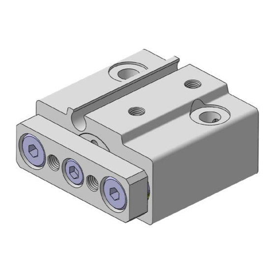
Summary of Contents for SMC Networks MGJ Series
- Page 1 MGJ*-OM0001O PRODUCT NAME Miniature Guide Rod Cylinder MODEL/ Series Series MGJ φ6, φ10...
-
Page 2: Table Of Contents
Contents 1. Safety Instructions 2. Product Specifications 2-1. Specifications 3. Installation and Handling 3-1. Air supply 3-2. Operating environment 3-3. Speed control 3-4. Direction control 3-5. Design 3-6. Mounting, Installation and others 3-7. Auto switches 4. Model Selection 4-1. Allowable kinetic energy 4-2. - Page 3 Series MGJ Safety Instructions These safety instructions are intended to prevent hazardous situations and/or equipment damage. These instructions indicate the level of potential hazard with the labels of “Caution,” “Warning” or “Danger.” They are all important notes for safety and must be followed in addition to International Standards (ISO/IEC), Japan Industrial Standards (JIS)*1) and other safety regulations*2).
-
Page 4: Product Specifications
2. Product Specifications 2-1. Specifications Tube I.D. (mm) Action Double acting Operating fluid Proof pressure 1.05MPa Max. operating pressure 0.7MPa Min. operating pressure 0.15MPa Ambient and fluid temperature -10 to 60 deg.C (No freezing) Cushion Rubber bumper at both ends Lubrication Not required. - Page 5 ! Caution 2) Install an air filter. Install an air filter close to the upstream side of the valve. A filtration degree of 5mm or less should be selected. 3) Install an aftercooler, air dryer or drain catch before the filter and take appropriate measures.
-
Page 6: Operating Environment
3-2. Operating environment ! Warning 1) Do not use in environments where there is a danger of corrosion. Refer to the construction drawings regarding cylinder materials. 2) Install a cover over the rod if it is used in an area that is dusty, or in an environment in which water or oil splashes on the cylinder. - Page 7 3) Securely tighten all stationary parts and connected parts so that they will not become loose. When the product operates with high frequency or is installed where there is a lot of vibration, ensure that all parts remain secure. 4) A deceleration circuit or shock absorber etc., may be required. When a driven object is operated at high speed or the load is heavy, the cylinder’s cushion will not be sufficient to absorb the shock.
-
Page 8: Mounting, Installation And Others
of individual cylinders, and the change of components over time. Therefore, it is possible to synchronize multiple cylinders for a short period of time by adjusting them with a speed controller. However, the synchronization could fail easily due to changes in various conditions. When the synchronization fails, the difference in position will apply an excessive force to the piston rod. - Page 9 4) Do not use the product until you have verified that the equipment can operate properly. After installation, repair or modification, apply compressed air and power supplies to the equipment and perform appropriate functional and leakage inspections to make sure the equipment is mounted properly.
-
Page 10: Auto Switches
9) Do not use this cylinder as a stopper. 3-7. Auto switches Refer to the catalog for the type of applicable auto switches and specifications. Also, for the handling of the auto switch, refer to the Operation Manual of the auto switch. 3-7-1. -
Page 11: Model Selection
3-7-3. Minimum mountable stroke for a cylinder with auto switch(es) The auto switches applicable to this cylinder may turn on in the entire stroke or two switches may turn on at the same time if the stroke is 5 or less. Be sure to secure the actual operating distance 4mm or more in order to avoid such errors. -
Page 12: Allowable Eccentric Load
4-3. Allowable eccentric load ! Caution Make sure that the load mass (W) is within the range in the graph below when there is an eccentric distance (L) from the center of the cylinder. Using cylinders are beyond the limit may shorten the product service life or cause damage. 4-4. -
Page 13: Pneumatic Circuit
5. Pneumatic Circuit The basic circuit (meter-out) for operating the product with air filter, regulator, solenoid valve and speed controller is shown in the following figure. Figure 5-1 6. Maintenance 6-1. Daily check 1) Smoothness of the operation 2) Changes in piston speed and cycle time 3) Proper stroking 6-2. -
Page 14: Troubleshooting
7. Troubleshooting Trouble Referential Trouble Cause Countermeasures section Operation is not Air leakage 1. Frictional wear of the rod seal due to 1. Ask SMC for replacement of smooth. (External scratches on the piston rod surface the rod seal. Force has leakage) 2. - Page 15 8. Basic Construction O-ring Piston seal Rod seal Oil-impregnated sintered Bushing bearing Magnet Magnet Bumper Resin Hexagon thin socket head Structural steel bolt Hexagon socket head cap For Φ10 Structural steel screw For Φ6 Torx head cap screw Structural steel Plate Aluminum alloy Guide rod...
- Page 16 Revision history 4-14-1, Stoked, Chiyoda-ku, Tokyo 101-0021 JAPAN Tel: + 81 3 5207 8249 Fax: +81 3 5298 5362 http://www.smcworld.com Note: Specifications are subject to change without prior notice and any obligation on the part of the manufacturer. © 2008 SMC Corporation All Rights Reserved...


Need help?
Do you have a question about the MGJ Series and is the answer not in the manual?
Questions and answers