
Related Manuals for SMC Networks MHR3-10


Summary of Contents for SMC Networks MHR3-10
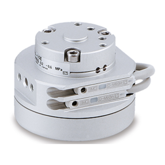
- Page 1 Doc. no. MH*-OMG0035 PRODUCT NAME Rotary Actuated Air Gripper MODEL / Series / Product Number M(D)HR3-10 M(D)HR3-15...
-
Page 2: Table Of Contents
Contents Safety Instructions 1. Product Specifications 2. Operating method or operation 2-1. Design precautions 2-2. Selection 2-3. Mounting 2-4. Air supply 2-5. Piping 2-6. Operating environment 2-7. Lubrication 3. Maintenance 3-1. Notes 3-2. Structural drawing / Parts List 3-3. For use without cover... - Page 3 Safety Instructions These safety instructions are intended to prevent hazardous situations and/or equipment damage. These instructions indicate the level of potential hazard with the labels of “Caution,” “Warning” or “Danger.” They are all important notes for safety and must be followed in addition to International Standards (ISO/IEC) , and other safety regulations.
- Page 4 Safety Instructions Caution The product is provided for use in manufacturing industries. The product herein described is basically provided for peaceful use in manufacturing industries. If considering using the product in other industries, consult SMC beforehand and exchange specifications or a contract if necessary. If anything is unclear, contact your nearest sales branch.
- Page 5 1.Specifications Specifications Model M(D)HR3-10 M(D)HR3-15 Nominal size Fluid Operation pressure MPa 0.2 to 0.6 0.15 to 0.6 Ambient and fluid temperature ℃ 0 to 60 ±0.01 Repeatability Max. operating frequency c.p.m. Lubrication Not required Action Double acting Note 1) External hold Holding force N Internal hold Opening stroke (Both side) mm...
-
Page 6: Design Precautions
2.Operation Guide for Air Gripper. 2-1 Design precautions ! Warning 1. A protective cover is recommended to minimize the risk of personal injury due to accidental contact with moving parts of the gripper. 2. Measures should be taken to protect against unexpected drop of work due to loss of air pressure. - Page 7 3. Please set roll on attachment if work is extra thin or extra fine. Product without roll off may cause incorrect positioning or incorrect holding, due to unstable holding. Run off space Needle shaped work 4. Select the model whose holding force is sufficient against work weight. Incorrect selection may lead to release of work etc.Refer to “Effective holding force”...
- Page 8 How to locate finger and attachment ・Positioning of finger open/close direction Position by finger pin and the attachment pin hole. C is the dimension of shorter diameter of the pin hole which is mating dimension referring to open/close direction. B is the dimension of longer diameter of the long oval and shall be set as clearance for adjustment for width direction.
-
Page 9: Mounting
Mounting of gripper Axial side mounting Axial side mounting Lateral side Vertical side mounting mounting B Auto switch mounting groove Vertical side mounting A MHR/without auto switch MDHR/with auto switch Vertical side Axial side Lateral side Model mounting mounting mounting ●... - Page 10 Lateral side mounting Location pin hole Max. tightening Max. screw-in Hole Mounting bolt Height Model depth (l) mm torque N⋅m diameter h mm d mm M(D)HR3-10 +0.02 M3x0.5 0.88 φ3 M(D)HR3-15 Vertical side mounting Location pin hole Max. tightening Max. screw-in Hole Mounting bolt Height...
- Page 11 ! Caution 1.Avoid the excessive force on fingers when mounting the attachment. Any change of fingers may cause the malfunction and deteriorate the accuracy. 2. Avoid external force to fingers. Fingers may be damaged by continual lateral or the impact load. Provide clearance to prevent the work or the attachment from striking against any object at the stroke end.
-
Page 12: Air Supply
3.Adjust the holding point so that excessive force will not be applied on fingers when inserting the work. Confirm that the gripper can operate without receiving any shock by testing with manual operation or low-speed operation. OK : Aligned NG : Not aligned 4.Speed control of finger full stroke slower than 0.2sec may cause slipstick or literally stop the operation. -
Page 13: Piping
2-5 Piping ! Caution 1.Preparation before piping. Thoroughly flush the fittings to prevent dust or chips from entering the gripper. Air gripper piping method Finger closing port Finger opening port Connection port Model Connection port M(D)HR3-10 M3x0.5 M(D)HR3-15 2-6 Operating environment ! Warning 1.Do not use in environment of corrosive grass, salt water, water, nor vapor. -
Page 14: Maintenance
3.Maintenance 3-1 Notes ! Warning 1.Do not enter the transfer line nor put the object. It may cause unexpected accidents. 2.Do not enter your hands between finger and attachment. It may cause unexpected accidents. 3.Confirm that no work is held by fingers before releasing the compressed air to remove the gripper from the line. -
Page 15: Structural Drawing / Parts List
3-2 Structural drawing / Parts List Component Parts Component Parts Description Material Note Description Material Note Body Hard anodized Stopper Aluminum alloy Resin Adaptor Body Hard anodized Back-up ring Aluminum alloy Stainless steel Hexagon socket Guide holder Stainless steel Stainless steel head bolt Nitriding Steel... - Page 16 3-3 For use without cover The cover can be replaced easy by taking off cross-recessed and flat head machine screw. When the cover is replaced, pay attention to prevent coarse particulates, chips, cutting lubricant from entering into the inside. Cross-recessed and flat head machine screw Tightening torque M(D)HR3-10∗...
- Page 17 Revision history 4-14-1, Sotokanda, Chiyoda-ku, Tokyo 101-0021 JAPAN Tel: + 81 3 5207 8249 Fax: +81 3 5298 5362 https://www.smcworld.com Note: Specifications are subject to change without prior notice and any obligation on the part of the manufacturer. © 2019 SMC Corporation All Rights Reserved...
Need help?
Do you have a question about the MHR3-10 and is the answer not in the manual?
Questions and answers