Advertisement
Quick Links
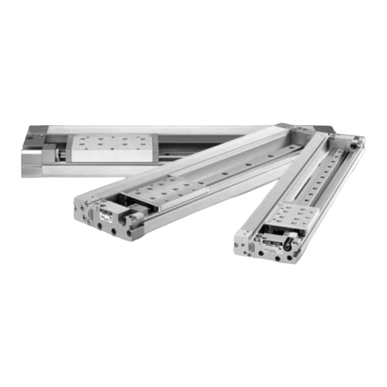
Mechanically Jointed Rodless Cylinder
MY2
Series
ø16, ø25, ø40
MY1B
MY1M
MY1C
MY1H
MY1HT
MY1„W
MY2C
MY2H„
MY3A
MY3B
MY3M
ompact and low profile design
D-„
-X„
Individual
-X„
Technical
data
1085
Courtesy of Steven Engineering, Inc.-230 Ryan Way, South San Francisco, CA 94080-6370-Main Office: (650) 588-9200-Outside Local Area: (800) 258-9200-www.stevenengineering.com
Advertisement

Related Manuals for SMC Networks MY2 Series


Summary of Contents for SMC Networks MY2 Series
- Page 1 Mechanically Jointed Rodless Cylinder Series ø16, ø25, ø40 MY1B MY1M MY1C MY1H MY1HT MY1„W MY2C MY2H„ MY3A MY3B MY3M ompact and low profile design D-„ -X„ Individual -X„ Technical data 1085 Courtesy of Steven Engineering, Inc.-230 Ryan Way, South San Francisco, CA 94080-6370-Main Office: (650) 588-9200-Outside Local Area: (800) 258-9200-www.stevenengineering.com...
- Page 2 Mechanically Jointed Rodless Cylinder Mechanically Jointed Rodless Cylinder Series Series Compact and low profile design A complete reduction in height of the cylinder allows mounting in a narrow space. The low profile design of the cylinder built with a high precision single or double axis guide, provides same load capacity as the earlier Series MY1.
- Page 3 (mm) (Compared to Series ø16 ø25 ø40 Height reduction by MY2C previous Series MY1.) MY2H (Single axis) MY2HT Low profile achieved by placing the guide unit and cylinder body next to one another. (Double axis) (dimension reduced by 12 mm to 26 mm) MY1C, MY1H ø16 / ø25 /...
-
Page 4: Model Selection
Series Model Selection 1 The following are the steps for selection of the series MY2 best suited to your application. Standards for Tentative Model Selection Graphs for related Cylinder Guide type Standards for guide selection model allowable values : Rolling : Pitching Note 2) Cam follower guide... - Page 5 Series Mechanically Jointed Rodless Cylinder Types of Moment Applied on Rodless Cylinders Multiple moments may be generated depending on the mounting orientation, load, and position of the center of gravity. Coordinates and Moments : Yawing MY1B MY1M MY1C MY1H MY1HT : Pitching MY1„W : Rolling...
- Page 6 Series Maximum Allowable Moment/Maximum Load Mass Maximum Allowable Moment Maximum load mass (kg) Maximum allowable moment (N⋅m) Bore size Model Select the moment from within the range of (mm) operating limits shown in the graphs. Note that the maximum load mass value may MY2C sometimes be exceeded even within the operating limits shown in the graphs.
- Page 7 Series Mechanically Jointed Rodless Cylinder Moment/MY2C MY2C/M MY2C/M MY2C/M MY1B MY1M MY1C MY1H MY2C40 MY1HT MY2C40 MY2C40 MY1„W MY2C MY2C25 MY2C25 MY2H„ MY2C25 MY3A MY3B MY2C16 MY3M MY2C16 MY2C16 200 300 400 500 1000 1500 200 300 400 500 1000 1500 200 300 400500 1000 1500 mm/s...
- Page 8 Series Maximum Allowable Moment/Maximum Load Mass Moment/MY2H (Single axis) MY2H/M MY2H/M MY2H/M MY2H40 MY2H40 MY2H40 MY2H25 MY2H25 MY2H25 MY2H16 MY2H16 MY2H16 200 300 400500 1000 1500 200 300 400500 1000 1500 200 300 400500 1000 1500 mm/s Piston speed mm/s Piston speed Piston speed mm/s...
- Page 9 Series Mechanically Jointed Rodless Cylinder Moment/MY2HT (Double axis) MY2HT/M MY2HT/M MY2HT/M MY1B MY1M MY1C MY1H MY1HT MY2HT40 MY1„W MY2HT40 MY2HT40 MY2C MY2HT25 MY2H„ MY2HT25 MY2HT25 MY3A MY3B MY2HT16 MY3M MY2HT16 MY2HT16 200 300 400500 1000 1500 200 300 400500 1000 1500 200 300 400 500 1000 1500 Piston speed...
- Page 10 Series Cushion Capacity Cushion Selection Absorption Capacity of Air Cushion and Stroke Adjusting Units <Air cushion> Air cushions are a standard feature on mechani- MY2C16 MY2H16 Horizontal impact: P = 0.5 MPa Horizontal impact: P = 0.5 MPa cally jointed rodless cylinders. The air cushion mechanism is installed to avoid 2000 2000...
- Page 11 Series Mechanically Jointed Rodless Cylinder MY2HT16 Horizontal impact: P = 0.5 MPa 2000 1500 MY1B 1000 MY1M MY1C MY1H 3 4 5 MY1HT max. max. Load mass MY1„W MY2C MY2HT25 Horizontal impact: P = 0.5 MPa 2000 MY2H„ H unit 1500 1000 MY3A...
- Page 12 Series Model Selection 2 The following are the steps for selection of the series MY2 best suited to your application. Calculation of Guide Load Factor Operating Conditions Mounting Orientation Cylinder MY2H40G-500 υ Average operating speed 300 mm/s 1. Horizontal mounting 2.
- Page 13 Series Mechanically Jointed Rodless Cylinder Calculation of Guide Load Factor : Moment max (from 3 of graph MY2H/M ) = 60 (N·m) MY1B g x X = 7.525 x 9.8 x 140.1 x 10 = 10.33 (N·m) MY1M α Load factor max = 10.33/60 = 0.17 MY1C Calculation of Load Factor for Dynamic Moment...
-
Page 14: How To Order
Mechanically Jointed Rodless Cylinder Linear Guide Type MY2H/HT Series ø16, ø25, ø40 How to Order MY1B MY1M H 16 M9NW Linear Guide Type MY1C Guide type MY1H Made to Order Linear guide, Single axis Refer to page Linear guide, Double axis 1106 for details. -
Page 15: Specifications
MY2H/HT Series Specifications Bore size (mm) Fluid Action Double acting Operating pressure range 0.1 to 0.8MPa Proof pressure 1.2MPa Ambient and fluid temperature 5 to 60 C Cushion Air cushion, Shock absorber Lubrication Not required (Non-lube) +1.8 Stroke length tolerance JIS Symbol Rc 1/4 Port size... - Page 16 Mechanically Jointed Rodless Cylinder MY2H/HT Series Linear Guide Type Theoretical Output Mass Unit: N Unit: kg Bore Piston (MPa) Operating pressure Stroke adjusting unit mass size area Additional (per unit) (mm) Bore size Basic mass Model (mm) mass per 50 mm of stroke L unit H unit...
- Page 17 MY2H/HT Series Construction MY2H Single axis type: MY2H16 MY2HT16 MY2H16 MY2HT16 !4 @5 !9 @3 !5 #1 @4 $4 !2 $3 #3 #5 #6 Component Parts Material Note Description Note Description Material Aluminum alloy Hard anodized Magnet Cylinder tube — Aluminum alloy Anodized Magnet...
- Page 18 Mechanically Jointed Rodless Cylinder MY2H/HT Series Linear Guide Type MY2HT Double axis type: MY1B MY1M MY1C MY1H MY1HT MY1„W MY2C MY2H„ MY3A MY3B MY3M Replacement Parts: Seal Kit Description MY2H16G/MY2HT16G MY2H25G/MY2HT25G MY2H40G/MY2HT40G Qty. Seal belt MY16-16A- Stroke MY25-16A- Stroke MY40-16A- Stroke Dust seal band MY2H16-16B- Stroke MY2H25-16B- Stroke...
- Page 19 MY2H/HT Series ø16, ø25, ø40 Single Axis Type: MY2H Bore size Stroke + Stroke (LL) 4 x ø depth of counterbore Cylinder mounting center line , depth ø through hole Workpiece mounting center line Long hole depth Guide center line 4 x 2 x square nut T-slot for body mounting MY2H40G...
- Page 20 Mechanically Jointed Rodless Cylinder MY2H/HT Series Linear Guide Type Stroke adjusting unit Low load shock absorber MY2H Bore size Stroke (Shock absorber stroke) MY1B Shock absorber Stroke adjusting unit MY1M MY1C MY1H MY1HT MY1„W MY2C Applicable cylinder Shock absorber model MY2H„...
- Page 21 MY2H/HT Series ø16, ø25, ø40 Double Axis Type: MY2HT Bore size Stroke + Stroke (LL) 4 x ø depth of counterbore , depth ø through hole Cylinder mounting center line Long hole depth Workpiece mounting center line LE H7 ø depth Cushion needle Workpiece mounting center line...
- Page 22 Mechanically Jointed Rodless Cylinder MY2H/HT Series Linear Guide Type Stroke adjusting unit Low load shock absorber MY2HT Bore size Stroke (Shock absorber stroke) MY1B Stroke adjusting unit MY1M Shock absorber MY1C MY1H MY1HT MY1„W MY2C Applicable cylinder Shock absorber model MY2H„...
- Page 23 Series Note) The operating range is a standard including hysteresis, and is Proper Auto Switch not guaranteed. There may be large variations depending on the Mounting Position (Detection at stroke end) surrounding environment (variations on the order of 30%). D-A9 , D-A9 V D-M9 , D-M9 V, D-M9 W, D-M9 WV Series model Operating range...
-
Page 24: Specific Product Precautions
Series Specific Product Precautions 1 Be sure to read before handling. Refer to front matters 54 and 55 for Safety Instructions and pages 3 to 11 for Actuator and Auto Switch Precautions. Selection Warning Caution 1. When using a cylinder with long strokes, implement 1. - Page 25 Series Specific Product Precautions 2 Be sure to read before handling. Refer to front matters 54 and 55 for Safety Instructions and pages 3 to 11 for Actuator and Auto Switch Precautions. Mounting Caution 1. Do not apply a strong impact or moment on the 4.
- Page 26 Series Specific Product Precautions 3 Be sure to read before handling. Refer to front matters 54 and 55 for Safety Instructions and pages 3 to 11 for Actuator and Auto Switch Precautions. Mounting Handling Caution Caution 11. Do not mount cylinders as they are twisted. 1.
- Page 27 Series Specific Product Precautions 4 Be sure to read before handling. Refer to front matters 54 and 55 for Safety Instructions and pages 3 to 11 for Actuator and Auto Switch Precautions. Operating Environment Warning 1. Do not use in environments where the cylinder will 2.
Need help?
Do you have a question about the MY2 Series and is the answer not in the manual?
Questions and answers