Advertisement
Quick Links
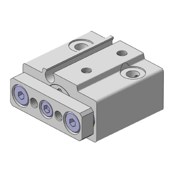
Miniature Guide Rod Cylinder
Non-rotating
accuracy :
Actual
size
( MGJ6-5 )
Width
Dimensions
Bore size
Overall length
6
23 + Stroke
10
25 + Stroke
Series Variations
Bore size
Series
(mm)
6
MGJ
10
Series
± 0.1˚
Mounting from 2
directions
Two auto switches can be
mounted even for 5 mm
strokes
Integral wiring/piping
to one direction
Unit: mm
Width
Height
29
14.5
33
17
Guide rod size
(mm)
5
5
6
MGJ
Weight
Bore size
(mm)
6
27.3
10
40.6
Standard stroke (mm)
10
15
20
-
CAT.ES20-181
Standard stroke (mm)
5
10
15
33.0
38.4
48.0
55.6
Cushion
Rubber bumper
(Both sides)
A
-UK
Unit: g
20
-
63.2
Auto switch
D-F8
Advertisement

Related Manuals for SMC Networks MGJ Series


Summary of Contents for SMC Networks MGJ Series
- Page 1 CAT.ES20-181 Miniature Guide Rod Cylinder Series ± 0.1˚ Non-rotating accuracy : Actual size ( MGJ6-5 ) Mounting from 2 directions Two auto switches can be mounted even for 5 mm strokes Integral wiring/piping to one direction Width Unit: g Dimensions Weight Unit: mm Standard stroke (mm)
-
Page 2: How To Order
Miniature Guide Rod Cylinder Series ø6, ø10 How to Order Miniature Guide 10 F8N Rod Cylinder Miniature Guide Rod Cylinder Number of auto switches 2 pcs. 1 pc. Bore size 6 mm 10 mm Auto switch type Without auto switch (built-in magnet cylinder) Cylinder stroke (mm) ∗... -
Page 3: Specifications
Series Miniature Guide Rod Cylinder Specifications Bore size (mm) Action Double acting Fluid Proof pressure 1.05 MPa Maximum operating pressure 0.7 MPa Minimum operating pressure 0.15 MPa Ambient and fluid temperature –10 to 60°C (with no freezing) Cushion Rubber bumper at both ends Lubrication Non-lube Note) - Page 4 Series Allowable Kinetic Energy Plate Allowable Lateral Load When driving the cylinder with inertial load, keep kinetic When the eccentric distance (L) generates from the plate energy no more than the allowable value. The area (rod end), be sure to keep the load weight (W) no more between bold lines in the below graphic shows the than a value in the below graphic.
- Page 5 Series Miniature Guide Rod Cylinder Dimensions ø 2-ø3.3 through 23 + Stroke Counterbore ø6.2 depth 0.5 18.5 + Stroke 4 x M3 depth 5 [ 23.3] 9 + Stroke 2-ø1.2 2 x M2.5 through (Guide air release) [Auto switch] 2-M3 x 0.5 (port size) 6.1 + Stroke 14.5...
- Page 6 Series Auto Switches/Proper Mounting Position for Stroke End Detection (mm) Bore size Operating range ø6 ø10 Auto Switch Mounting Watchmakers screw driver Auto switch mounting screw • Use a watchmakers screw driver with a handle about 5 to 6 mm in diameter when tightening the auto switch mounting screw.
- Page 7 Series Auto Switch Common Specifications Auto Switch Common Specifications Solid state switch Type 1 ms or less Operating time 1000 m/s Impact resistance 50 MΩ or more at 500 VDC M (between lead wire and case) Insulation resistance 1000 VAC for 1 minute Withstand voltage (between lead wire and case) –10 to 60°C...
- Page 8 Series Auto Switch Connections and Examples Basic Wiring Solid state 3-wire, NPN Solid state 3-wire, PNP 2-wire (Solid state) Brown Brown Brown Load Load Switch Switch Switch Black Black main main main circuit circuit circuit Load Blue Blue Blue (Power supplies for switch and load are separate.) Brown Brown Load...
- Page 9 Solid State Switches: Direct Mounting Type D-F8N/D-F8P/D-F8B Refer to www.smcworld.com for details of products compatible with overseas standards. Auto Switch Specifications Grommet PLC: Programable Logic Controller D-F8N D-F8P D-F8B Auto switch part No. Electrical entry direction Perpendicular Perpendicular Perpendicular 3-wire Wiring type 2-wire Output type...
-
Page 10: Safety Instructions
Series Safety Instructions These safety instructions are intended to prevent a hazardous situation and/or equipment damage. These instructions indicate the level of potential hazard by a label of Note 1) “Caution”, “Warning” or “Danger”. To ensure safety, be sure to observe ISO 4414 Note 2 JIS B 8370 and other safety practices. - Page 11 Series Actuator Precautions 1 Be sure to read before handling. Design Design Selection Warning Warning 1. There is a possibility of dangerous sudden 1. Check the specifications. action by air cylinders if sliding parts of ma- The products featured in this catalogue are designed for use in industrial compressed air systems.
- Page 12 Series Actuator Precautions 1 Be sure to read before handling. Piping Air Supply Caution Caution 1. Preparation before piping 1. Install air filters Before piping is connected, it should be thoroughly blown out Install air filters at the upstream side of valves. The filtration degree should be 5 μm or finer.
- Page 13 Series Auto Switch Precautions 1 Be sure to read before handling. Design and Selection Warning 1. Check the specifications. 6. Pay attention to leakage current. Read the specifications carefully and use this product <Solid state switches> appropriately. The product may be damaged or malfunction if it With a 2-wire solid state auto switch, current (leakage current) is used outside the range of specifications of current current, flows to the load to operate the internal circuit even when in the...
- Page 14 Series Auto Switch Precautions 2 Be sure to read before handling. Mounting and Adjustment Mounting and Adjustment Wiring Warning Warning 5. Do not allow short circuiting of loads. 1. Do not drop or bump. <Solid state switches> Do not drop, bump or apply excessive impacts (1000 m/s more for solid state switches) while handling.
- Page 15 Series Auto Switch Precautions 3 Be sure to read before handling. Operating Environment Maintenance Warning Warning 1. Never use in the presence of explosive gases. 1. Perform the following maintenance periodi- cally in order to prevent possible danger due The construction of our auto switches does not make them explosion-proof.
-
Page 16: Specific Product Precautions
Series Specific Product Precautions Be sure to read before handling. Mounting Mounting Warning Caution 1. Do not put hands or fingers, etc. between the 4. Flatness of mounting surface should be less plate and body. than 0.02 mm. Care should be taken that hands or fingers do not get caught in When mounting Miniature Guide Rod Cylinder, or mounting between the cylinder body and the plate when air pressure is plate to work piece, sideling mounting surface may cause...
Need help?
Do you have a question about the MGJ Series and is the answer not in the manual?
Questions and answers