
Related Manuals for SMC Networks MWB 32-UT Series


Summary of Contents for SMC Networks MWB 32-UT Series
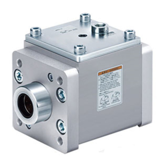
- Page 1 Doc. no.MWB*-OM0078Q PRODUCT NAME Lock unit MODEL / Series / Product Number MWB*32&100-UT-* MWB*32&100TN-UT-* MWB*32&100TF-UT-*...
-
Page 2: Table Of Contents
Contents Safety Instructions P. 3 1. Product Specifications P. 5 1-1. Lock unit specifications 1-2. Stop accuracy 1-3. Precautions on model selection 2. Installation and Handing P. 8 2-1. Air supply 2-2. Design 2-3. Mounting 2-4. Operating environment 2-5. Pneumatic circuit 2-6. -
Page 3: Safety Instructions
Safety Instructions These safety instructions are intended to prevent hazardous situations and/or equipment damage. These instructions indicate the level of potential hazard with the labels of “Caution,” “Warning” or “Danger.” They are all important notes for safety and must be followed in addition to International Standards (ISO/IEC) , and other safety regulations. - Page 4 Safety Instructions Caution 1. The product is provided for use in manufacturing industries. The product herein described is basically provided for peaceful use in manufacturing industries. If considering using the product in other industries, consult SMC beforehand and exchange specifications or a contract if necessary. If anything is unclear, contact your nearest sales branch.
-
Page 5: Product Specifications
1. Product Specifications 1-1. Lock unit specification Lock unit model MWB∗32-UT MWB∗40-UT MWB∗50-UT MWB∗63-UT MWB∗80-UT MWB∗100-UT Applicable rod size mm *2 Ø12 f8 Ø16 f8 Ø20 f8 Ø20 f8 Ø25 f8 Ø30 f8 Locking operation type Exhaust locking Fluid Proof pressure 1.5MPa Max. -
Page 6: Precautions On Model Selection
1-3.Precautions on model selection ! C a u t i o n ① Choose the optimum lock unit size based on the operating condition in the application , such as load , travel distance (stroke) , stroke time , mounting orientation , operating pressure, etc. ②... - Page 7 Selection graph - 7 -...
-
Page 8: Installation And Handing
2. Installation and Handling 2-1. Air supply ① The air supplied to the lock unit should be filtered by SMC AF series air filter and regulated to the specified set pressure by SMC AR series regulator. ! W a r n i n g ・Type of fluids Please contact SMC when using the product in applications other than with compressed air. -
Page 9: Design
2-2. Design The compatibility of the product is the responsibility of the person who designs the equipment or decides its specifications ! W a r n i n g - Refer to section 1-3 Precautions on model selection. - Refer to the table below for the recommended rod dimensions. Lock unit model MWB∗32 MWB∗40... - Page 10 [Use with air cylinder] ! W a r n i n g ・There is a possibility of dangerous sudden action by cylinders if force is changed due to twisting of sliding parts of machinery. In such cases, human injury may occur; e.g., by catching hands or feet in the machinery, or damage to the machinery itself may occur.
-
Page 11: Mounting
Fig. 3.Example when operated with the rodless cylinder 2-3. Mounting The foot mounting cylinder has a hole in the foot to drive a pin into for accurate positioning and fixing. ! C a u t i o n - Be careful not to scratch or damage the sliding surface of the rod while mounting it to the product or during maintenance. -
Page 12: Operating Environment
2-4. Operating envi ronment ! W a r n i n g ・Do not use in an atmosphere having corrosive gases, chemicals, sea water, water, water steam, or where there is direct contact with any of these. ・Provide a protective cover if the product is used in direct sunlight. ・Do not operate in environments subject to heavy vibration and/or impact. - Page 13 [Use with air cylinder] ③ Use the pneumatic circuit which applies balance pressure to the both sides of the piston when locking. To prevent sudden extension when operation restarts or lock is released, control the cylinder to make balancing pressure applied to both sides of the piston so that the force generated in the operating direction of the piston due to load can be counteracted.
-
Page 14: Adjustment And Operation
! C a u t i o n ① One 3-position pressure center solenoid valve and a regulator with check valve can be replaced by 2 3-port normally open valves and a regulator with a relief valve. Cylinder side Cylinder side 1. -
Page 15: How To Use
3. How to Use 3-1. Usage ① For intermediate stop, take stopping accuracy and overrun into consideration. As this is a mechanical lock, there will be a slight time difference for the stop signal and delay of the cylinder. The cylinder stroke during the delay is called overrun. The range between maximum and minimum overrun is referred to as overrun. -
Page 16: Lock Release Mechanism
3-2. Lock release mechanism Operation principle for unlocking mechanism. Hexagon wrench Unlocking port (Exhaust air pressure) Spring Release bolt Locked Manually unlocked Fig. 7 Operation principle of locking mechanism (Fig. 7 is for reference for the operation principle. (Different from the actual structure)) !... - Page 17 ! W a r n i n g (1) Do not operate the release bolt until safety is confirmed. Do not twist a) Examples when used in combination with an air cylinder. b) Carefully confirm that personnel are not within the moving range of the load and there is no danger, even if the load moves suddenly.
-
Page 18: Maintenance
4. Maintenance Do not disassemble the lock unit or perform maintenance. Replace the complete lock unit instead. 4-1. Checks 4-1-1. Inspection points ① Check the tightness of the mounting bolts (hexagon socket head cap screw) holding the lock unit. ② Operation of the lock unit. Overrun and the stopping accuracy. ③... -
Page 19: Troubleshooting
5. Troubleshooting Reported failure Major causes Countermeasures Air piping is not connected to the lock unit. Or air supplied Connect piping to the lock unit and supply ① to the lock unit is not 0.3MPa or more air. adequate for operation. ・Check the power supply to the solenoid valve ・Check that the wiring of the solenoid... - Page 20 Manual lock is released. Check the operating conditions to replace ① (Check the condition of the with the optimum type and size of the lock release bolt) guide. Air of the lock unit is not ・nstall the solenoid valve for locking close exhausted.
- Page 21 Reported failure Major causes Countermeasures Effective area of the Replace the solenoid valve to the one ① solenoid valve for locking with larger effective area. is too small. ・Install the solenoid valve for locking Piping between the lock release port and the close to the lock unit and shorten the ②...
- Page 22 [Used with air cylinder] Reported failure Major causes Countermeasures Air piping is not connected to the cylinder or air ・Check the air piping of the cylinder supplied to the ・Increase the operating pressure of ① lock unit is not the cylinder. adequate for ・Use a larger cylinder.
- Page 23 Change to recommended balanced a. The circuit is not circuit. (Refer to Page 13 to 14) balanced. b. Adjust the regulator valve. Check b. Regulator for if the locked status is balanced. balancing pressure Sudden extension of the c. Install an air tank so that pressure is not adjusted.
-
Page 24: Construction
6. Construction Description Material Note BRAKE BODY Aluminum alloy Hard anodized BODY CAP Rolled steel Zinc chromated COLLAR Aluminum alloy Chromated HOLDER Aluminum alloy Anodized BRAKE METAL Cast iron PISTON A Aluminum alloy ROLLER HOLDER Carbon steel ROLLER PLATE Stainless steel Heat treatment NEEDLE ROLLER Carbon steel... - Page 25 Revision history 4-14-1, Sotokanda, Chiyoda-ku, Tokyo 101-0021 JAPAN Tel: + 81 3 5207 8249 Fax: +81 3 5298 5362 http://www.smcworld.com Note: Specifications are subject to change without prior notice and any obligation on the part of the manufacturer. © 2011 SMC Corporation All Rights Reserved...
Need help?
Do you have a question about the MWB 32-UT Series and is the answer not in the manual?
Questions and answers