Table of Contents

Related Manuals for Mandik alnor FDMD


Summary of Contents for Mandik alnor FDMD
- Page 1 ® E N 1 5 6 5 0 : 2 0 1 0 A L N O R S y s t e my We n t y l a c j i S p . z o . o . A l e j a K r a k o w s k a 1 0 , 0 5 - 5 5 2 Wo l a Mr o k o w s k a t e l .
-
Page 2: Table Of Contents
TPM 092/13 These technical specifications state a row of manufactured sizes and models of fire dampers (further only dampers) FDMD. It is valid for production, designing, ordering, delivery, assembly and operation. I. CONTENT II. GENERAL INFORMATION 1. Description......................... 2. Design..........................3. -
Page 3: General Information
TPM 092/13 II. GENERAL INFORMATION 1. Description 1.1. Fire dampers are shutters in piping systems of air-conditioning devices that prevent spreading the fire and combustion products from one fire segment to the other one by means of closing the air piping in the points of fire separating constructions. 1.2. -
Page 4: Design
TPM 092/13 2. Design 2.1. Design with mechanical control 2.1.1. Design with mechanical control with a thermal protective fuse which actuates the shutting device within 120 seconds at latest after the nominal start temperature 73 °C has been reached. Automatic initiation of the shutting device is not activated if the temperature does not exceed 70 °C. - Page 5 TPM 092/13 2.3. Communication and control devices 2.3.1. BKS 24-1B communication and control device is used for control and checks of fire flap valves with the BLF 24-T-ST actuating mechanism in conjunction with the BKN 230-24 supply and communication device. BKS 24-1B receives information about the situation of the fire damper through the BKN 230-24 supply and communication device and issues controlling commands.
- Page 6 TPM 092/13 Tab. 2.4.1. Dampers design Dampers design Additional digit Thermal Thermal with a terminal switch ("CLOSED") With actuating mechanism BLF 230-T With actuating mechanism BLF 24-T With communication and supply device BKN 230-24 and actuating mechanism BLF 24-T-ST* * communication and supply device BKN 230-24 has to be placed near the damper. It is necessary for easy connection of actuating system equipped by BKN 230-24 device.
-
Page 7: Placement And Assembly
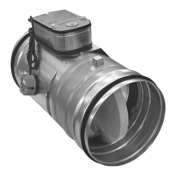
TPM 092/13 Fig. 3 Fire damper FDMD - design with actuating mechanism Position: Damper casing Terminal switch Damper blade Inspection hole covering Shutting spring Actuating mechanism Thermal protective fuse BAE 72B-S thermoelectrical starting mechanism 3.2. Weights and effective area Tab. 3.2.1. Weights and effective area Weight [kg] Size Actuating... - Page 8 TPM 092/13 4.2. To provide needed access space to the control device, all other objects must be situated at least 350 mm from the control parts of the damper. Inspection hole must be accessible. 4.3. The distance between the fire damper and the construction (wall, ceiling) must be minimum 75 mm.
-
Page 9: Statement Of Installations
TPM 092/13 Fig. 8 Installation opening - system Weichschott 5. Statement of installations 5.1. Statement of installations Tab. 5.1.1. Statement of installations Classifi- Size FDMD installation Figure cation Damper installed in a solid wall construction min. thickness 100 mm. EIS 90 Space between damper and wall is filled by mortar, gypsum (notice 1) Damper installed in a solid wall construction min. - Page 10 TPM 092/13 Fig. 9 Installation in a solid wall construction POSITION Fire damper FDMD Mortar or gypsum with min. density 800 kg/m Fig. 10 Installation in a solid wall construction POSITION Fire damper FDMD Stuffing box (mineral stone wool min. density 140 kg/m Fire protection mastic min.
- Page 11 TPM 092/13 Fig. 12 Installation in a gypsum construction POSITION Fire damper FDMD Stuffing box (mineral stone wool min. density 140 kg/m Fire protection mastic min. thickness 1 mm Used materials - example*: Promapyr, Rockwool Steprock HD * Stuffing box and fire protection mastic can be replaced by another approved Promastop - P, K fire sealing system for damper installation with equivalent material properties.
-
Page 12: Technical Data
TPM 092/13 Fig. 15 Installation in a solid ceiling construction POSITION * Stuffing box and fire protection mastic Used materials - example*: Fire damper FDMD can be replaced by another approved Promapyr, Rockwool Steprock HD fire sealing system for damper Stuffing box (mineral stone wool installation with equivalent material Promastop - P, K... -
Page 13: Coefficient Of Local Pressure Loss
TPM 092/13 6.2. Determination of pressure loss by using diagram 6.2.1. = 1,2 kg.m Diagram 6.2.1. Pressure losses for air density =1,2 kg.m 7. Coefficient of local pressure loss 7.1. Coefficient of local pressure loss Tab. 7.1.1. Coefficient of local pressure loss 2,736 2,099 1,781... - Page 14 TPM 092/13 8.3. Table of acoustics values Tab. 8.3.1. Level of acoustic output L related to the 1 m section w [m.s 11,5 14,7 16,9 20,1 22,3 24,1 27,2 29,4 31,2 32,6 33,8 16,7 22,1 25,3 27,5 30,7 32,9 34,6 37,8 40,0 41,7...
-
Page 15: Electrical Components, Connection Diagrams
TPM 092/13 Fig. 17 Calculation example Given data Fire damper FDMD 200 V = 600 m = 1,2 kg.m Octave range 1000 Hz Tab. 3.2.1. = 0,0213 m Calculation: w [m.s ] = (V [m ] / 3600) / S w = 7,83 m.s Tab. - Page 16 TPM 092/13 Fig. 18 Actuating mechanism BELIMO BLF 24-T(-ST) Fig. 19 Servopohon BELIMO BLF 230-T 9.2. Communication and Supply Device Tab. 9.2.1. Communication and Supply Device BKN 230-24 Communication and Supply Device BKN 230-24 Nominal voltage AC 230V 50/60Hz Power consumption 3,5 W (operating position) Dimensioning 11 VA (including actuating mechanism)
- Page 17 TPM 092/13 Fig. 20 Communication and Supply Device BKN 230-24 9.3. Communication and Control Devices Tab. 9.3.2. Communication and Control Device BKS 24-9A BKS 24-9A Communication and Control Device Nominal voltage AC 24 V 50/60Hz Power consumption 3,5 W (operating position) Dimensioning 5,5 VA Protection Class...
- Page 18 TPM 092/13 Tab. 9.3.1. Communication and Control Device BKS 24-1B BKS 24-1B Communication and Control Device Nominal voltage AC 24 V 50/60Hz Power consumption 2,5 W (operating position) Dimensioning 5 VA Protection Class III (safe small voltage) Degree of protection IP 30 Ambient Temperature 0 …...
-
Page 19: Ordering Information
TPM 092/13 IV. ORDERING INFORMATION 10. Ordering key FDMD - .40 TPM 092/13 technical specifications design acc. dle Tab. 2.3.1. size type V. DATA OF THE PRODUCT 11. Data label 11.1. Data label is placed on the casing of fire damper. Fig. -
Page 20: Transportation And Storage
TPM 092/13 VIII. TRANSPORTATION AND STORAGE 14. Logistic terms 14.1. Dampers are transported by box freight vehicles without direct weather impact, there must not occur any sharp shocks and ambient temperature must not exceed + 40 °C. Dampers must be protected against mechanic damages when transported and manipulated. - Page 21 Wy ł ą c z n y D y s t r y b u t o r P r o d u c e n t A L N O R S y s t e my We n t y l a c j i S p . z o . o . A l e j a K r a k o w s k a 1 0 0 5 - 5 5 2 Wo l a M r o k o w s k a P o l s k a...
Need help?
Do you have a question about the alnor FDMD and is the answer not in the manual?
Questions and answers