
Related Manuals for Mandik CFDM


Summary of Contents for Mandik CFDM
- Page 2 These technical specifications state a row of manufactured sizes and models of fire dampers (further only dampers) CFDM. It is valid for production, designing, ordering, delivery, assembly and operation. 1. Description......................... 2. Damper Design..…......................3. Dimensions, weights......................4. Placement and Assembly....................
- Page 3 • Internal leakage class 2 acc. to EN 1751, external leakage is equal to ducting system • Corrosion resistant acc. to EN 15650 • ES Certificate No. 1391-CPR-2016/0082 • Declaration of Perfomance No. PM/CFDM/01/16/1 Working conditions Exact damper function is provided under the following conditions: a) Maximum air circulation speed: 12 m.s...
- Page 4 Dampers are designed for macroclimatic areas with mild climate according to EN 60 721-3-3. Temperature in the place of installation is permitted to range from - 20°C to + 50°C. Design with mechanical control Design with mechanical control with a thermal protective fuse (inner mechanical control which actuates the shutting device within 120 seconds at latest after the nominal start temperature 72 °C has been reached.
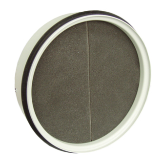
- Page 5 Nominal voltage, current DC 30 V; 0,1 A Degree of protection IP 67 Ambient temperature -40 °C … 85 °C black white Dimensions Damper casing Damper blade Shutting spring Thermal fuse Locking planchet Fire damper CFDM Dish valve Duct...
- Page 6 Weights and effective area 0,0027 15,5 0,0056 0,55 0,0115 45,5 0,75 0,0206 72,5 Fire dampers are suitable for installation in arbitrary position in vertical and horizontal passages of fire separating constructions. Duct assembly procedures must be done so as all load transfer from the fire separating constructions to the duct in the placement of fire damper installation is absolutely excluded.
- Page 7 Installation opening dimensions (see Fig. 9-11) Examples of fire damper installing The fire damper can be integrated into a solid wall construction made e.g. of normal concrete/ masonry, porous concrete with minimum thickness 100 mm or into solid ceiling construction made e.g.
- Page 8 Statement of installations the fire dampers CFDM mortar or gypsum mineral wool boards with fire resistant coating mortar or gypsum mineral wool boards with fire resistant coating mortar or gypsum mineral wool boards with fire resistant coating Make installation Install duct in...
- Page 9 Used materials - example*: 3 - Hilti CFS-CT B 1S 140/50 4 - Hilti CFS-CT Position: 1 Fire damper CFDM 2 Solid wall construction 3 Fire resistant board Fire resistant board and fire stop coating can be 4 Fire stop coating thickness 1 mm replaced by another approved fire sealing system for damper installation with equivalent material properties.
- Page 10 Installation opening has to be reinforced by profile (UW, CW). Profil is fixed by screws ≥3,5 mm with corresponding length. Distance between screws ≤200 mm. ≥ 100 Position: 1 Fire damper CFDM 2 Solid wall construction 3 Mortar or gypsum 4 Duct...
- Page 11 Used materials - example*: 3 - Hilti CFS-CT B 1S 140/50 4 - Hilti CFS-CT Position: 1 Fire damper CFDM 2 Gypsum wall construction 3 Fire resistant board Fire resistant board and fire stop coating can be 4 Fire stop coating thickness 1 mm replaced by another approved fire sealing system for damper installation with equivalent material properties.
- Page 12 Install duct in Opening the Opening Fill gap Insert damper in the duct ≥ 25 150* * min. 110 - Concrete/ min. 125 - Aerated concrete Position: 1 Fire damper CFDM 2 Solid wall construction 3 Mortar or gypsum 4 Duct...
- Page 13 * min. 110 - Concrete/ min. 125 - Aerated concrete 3 - Hilti CFS-CT B 1S 140/50 4 - Hilti CFS-CT Position: 1 Fire damper CFDM 2 Ceiling wall construction Fire resistant board and fire stop coating can be 3 Fire resistant board...
- Page 14 Install duct together with Insert damper in distance 50 construction edge mm from the edge in the duct Insert valve housing in the duct Insert valve in the housing and screw to the construction Pressure loss calculation [Pa] pressure loss [m.s ] air flow speed in nominal damper section [kg.m ]...
- Page 15 Coefficient of local pressure loss 1,836 1,083 0,7407 0,4167 Given data Fire damper CFDM 200 V = 600 m .h = 1,2 kg.m Tab. 3.2.1. = 0,0206 m Calculation: w [m.s ] = (V [m .h ] / 3600) / S [m ] w = 8,09 m.s...
- Page 16 Damper casing are supplied in the design made of galvanized sheet without any other surface finishing. Damper blades are made of fire resistant asbestos free boards made of mineral fibres. Damper controls are made of stainless steel with no other surface finish. Springs are made of stainless steel.
- Page 17 It is recommended to provide periodical checks, maintenance and service actions on Fire Equipment by Authorized persons schooled by Producer. Data label is placed on the casing of fire damper. Požární klapka / Fire damper / MANDÍK, a.s. Dobříšská 550 Brandschutzklappe / Clapet coupe-feu 267 24 Hostomice Czech Republic...
- Page 18 technical specifications TVO - disch valve outlet TVP - disch valve inlet 60 - EIS60 90 - EIS90 120 - EIS120 design acc. Tab. 17.1.1. size type Thermal with inner mechanical control Thermal with inner mechanical control and limit switch („CLOSED“) Thermal with inner mechanical control and two limit switches („CLOSED“)
- Page 20 MANDÍK, a.s. Dobříšská 550 26724 Hostomice Czech Republic Tel.: +420 311 706 706 Fax: +420 311 584 810, 311 584 38 E-Mail: mandik@mandik.cz www.mandik.com The producer reserves the right for innovations of the product. For actual product information see www.mandik.com...
Need help?
Do you have a question about the CFDM and is the answer not in the manual?
Questions and answers