Advertisement
FWA-6510 Intel® Xeon® E5-2600 Series Processor
based 2U Network Application Platform
Startup Manual
Packing List
Before you begin installing your card, please make sure that
the following items have been shipped:
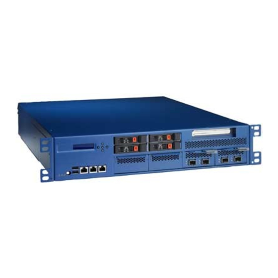
• One FWA-6510 Internet Security Platform
• One box of accessories
• One warranty certificate
If any of these items are missing or damaged, please con-
tact your distributor or sales representative immediately.
Note 1:
Acrobat Reader is required to view any PDF
file.Acrobat Reader can be downloaded at:
www.adobe.com/Products/acrobat/readstep2.
html (Acrobat is a trademark of Adobe)
For more information on this and other Advantech
products, please visit our website at:
http://www.advantech.com.tw/support
http://www.advantech.com
For technical support and service, please visit our
support website at:
http://www.advantech.com/support
This manual is for the FWA-6510 series Rev. A
Part No. 2002651000
Print in China
Specifications
Main Board Functions
• CPU: 2 x Intel® Xeon® E5-2600 processors
• PCH: Intel C600 series chipset
• BIOS: AMI 8Mbit SPI Flash
• QPI: up to 8 GT/s
• Memory: System memory: Support for DDR3
800/1066/1333/1600 memory ECC RDIMM
Primary CPU support 2 DIMMs/channel, up to 8 DIMMs
Secondary CPU support 1 DIMM/channel, up to 4 DIMMs,
Capacity up to 384 GB with 12 slots.
• PCIe Bus:
- PCH: Intel C600 series chipset
- Expansion:
- Riser card: 1 x PCIe x8 riser card, Supports
• NMC modules: 4 x NMC modules with PCIex8 gen.3
InterfacesMaximum 32 GbE ports or 8 x 10GE ports
• Storage:
- SAS/SATA: 4 x 2.5" hot-swappable SAS/SATA
- Compact Flash: 1 x CFast socket
- USB Flash Disk: 4 x USB 2.0 on-board pinheader for
• System Management: IPMI, Aspeed AST2300 iBMC +
AMI MegaRAC firmware, Supports IPMI 2.0
Supports iKVM
• Dimensions/ Weight: 430 x 558 x 88 mm/ 18Kg
• Power Supply: 720 W 2U (1+1 redundant, 720 W
each),AC 100 ~ 240 V @ 50 ~ 60 Hz, full range, With
PMBus support
• Environment:
• Temperature:
• Humidity:
Management Ports
• LAN: 2 x Intel 82574L 10/100/1000 Base-T Ethernet
• USB: 2 x USB 2.0 ports on the front
• Serial:1 x RS232 console port by RJ-45 connector on
the front.
• LCD: 16 x 2 character display, 5 buttons
• VGA: Pin header (for debug only)
• TPM: TPM1.2 compliant (Infineon SLB9635TT1.2)
1st Edition,
March 2012
4 x PCIe Gen3 x8 slots connect to NMC modules (2 per
CPU socket)
1 x PCIe Gen3 x8 slot for riser card (primary CPU)
2 x PCIe Gen1 for management boards (PCH)
USB flash disk (DOM)
Operating
0 ~ 40° C
(32 ~ 104° F)
5~85%@40°C
(104° F)
FWA-6510 Startup Manual 1
Non-Operating
-20° ~ 75° C
(-4 ~ 167° F)
5~95%
Advertisement
Table of Contents

Related Manuals for Advantech FWA-6510


Summary of Contents for Advantech FWA-6510
- Page 1 For technical support and service, please visit our • VGA: Pin header (for debug only) support website at: • TPM: TPM1.2 compliant (Infineon SLB9635TT1.2) http://www.advantech.com/support This manual is for the FWA-6510 series Rev. A Part No. 2002651000 1st Edition, Print in China March 2012...
-
Page 2: Specifications
4. Close the load plate and push the load lever back down until it engages the retention tab. Figure 2A: NMC-0108 4 ports SFP Module Figure 3A: NMC-0803 8 ports Copper Module Figure 4A: NMC-1004 2 ports 10G SFP+ Module 2 FWA-6510 Startup Manual... -
Page 3: Installing The Heat Sinks
Installation Installing the Heat sinks Installing the Memory The FWA-6510 system provides 12 x DDR3 DIMMs which 1. Taking one heat sink at one time, apply a small dab of can support up to DDR3 800/1066/1333/1600 MHz 384GB. heat transfer compound to the top of the installed CPU, 1. -
Page 4: Jumpers And Connectors
PIN HEADER 3x1P for CLR RTC Keep CMOS data* Clear CMOS data Connector / Jumper List PIN HEADER 3x1P for CLR CMOS PIN HEADER 3x1P for BIOS Recovery Mode Jumper PIN HEADER 3x1P for BMC UART Debug 4 FWA-6510 Startup Manual... -
Page 5: Software Installation
1. This device may not cause harmful interference. 2. This device must accept any interference received, Pins Result including interference that may cause undesired opera- tion. Power Button Reset Button SMBUS Data SMBUS Clock VCC3 HDD ACT LED FWA-6510 Startup Manual 5... -
Page 6: Board Placement
Board Placement CN31 CN18 CN11 CN17 CN14 CN13 CN19 CN20 CN16 CN32 CN15 CN21 CPU1 CPU2 CN24 CN23 CN22 FAN2 FAN1 CN25 CN26 CN27 6 FWA-6510 Startup Manual... - Page 7 Board Placement CN10 CN11 CASE_OPEN1 FWA-6510 Startup Manual 7...
Need help?
Do you have a question about the FWA-6510 and is the answer not in the manual?
Questions and answers