Advertisement
Quick Links
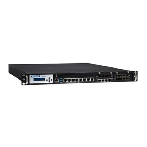
1U Rackmount Network Appliance with 10 GbE LAN ports and 2NMC
Slots based on Intel Coffee Lake CPU Xeon® E family and 8th/9th gen.
Intel® Core™ i7/i5/i3 processors
Startup manual
Before installation, ensure that the following materials have been received:
One Internet Security Platform
One box of accessories
One warranty certificate
Part Number List
FWA-3033-00A1R
FWA-3033L-00A1S
Specification
Main Board Functions
TM
CPU: Intel® Xeon
E-2226GE/ E-2278GE/ E-2124G/ E-2176G, 8/9th Gen Intel® Core
I5-9500E, I3-9100E, Intel® Pentium® Processor G5400, Intel® Celeron® Processor G4900
Chipset: Intel® C246
Memory: 4 x DDR4 UDIMMs, 2400/2666 MHz, up to 128GB memory capacity
PCI-Express: 2 PCIe x8 Size slots for HL/FL PCIE card, one slot bandwidth is PCIEx4 Gen3, another is PCIEx2 Gen3; 1 Mini-PCIE
reserved on Riser
Network Connectivity:
NMC Modules: 2 NMC slots, with PCIe Gen3 x8 Connectivity
Management: 6-8 LAN ports onboard by 10/100/1000 Base-T Ethernet, 4 SFP ports onboard (SKU option)
Mass Storage: 2 x 3.5" internal SATA HDD/SSD, 1 x M.2 2260/2280 Slot, M-Key
Peripherals:
LCD Module: 16 x 2 graphic display, 5 buttons
Console:1 x RJ45 Console port
USB: 2 x USB3.0 Type A on Front
LAN: 6-8 x Intel i210-AT 10/100/1000 Base-T Ethernet
Power supply: 300W FSP AC and DC redundant, or 250W Delta AC single
Dimensions (W x H x D): 438 x 44 x 550 mm
Weight:15KG
Environment: Operating / Non-operating
Temperature: 0 ~ 40℃ / -40 ~ 60℃
(32 ~ 104° F) / (-40 ~ 140° F)
Humidity: 40° C @ 5 ~ 95% RH Non-Condensing
TM
Processors I7-8700, I5-8500, I3-8100, I7-9700E,
Advertisement

Related Manuals for Advantech FWA-3033-00A1R


Summary of Contents for Advantech FWA-3033-00A1R
- Page 1 Before installation, ensure that the following materials have been received: One Internet Security Platform One box of accessories One warranty certificate Part Number List FWA-3033-00A1R FWA-3033L-00A1S Specification Main Board Functions CPU: Intel® Xeon E-2226GE/ E-2278GE/ E-2124G/ E-2176G, 8/9th Gen Intel® Core Processors I7-8700, I5-8500, I3-8100, I7-9700E, I5-9500E, I3-9100E, Intel®...
-
Page 2: Installation
FWA-3033 Internet Security Platform FWA-3033-00A1R Front view FWA-3033-00A1R Back view FWA-3033L-00A1S Front view FWA-3033L-00A1S Back view Installation Set up To unpack, first remove 9 screws on the side of the machine by referring to the arrows below. - Page 3 Installing the CPUs Taking one CPU at a time, remove the protective shield, if present, and press the load lever and move it out till it is clear of the retention tab, and raise it. Make sure that alignment triangle on the CPU lines up with the correct corner on the socket, and ease the CPU into place. Close the load plate and push the load lever back down until it engages the retention tab.
- Page 4 Installing the heatsink and air scoop Take out Heatsink, Fan cover and 4 screws from the accessory box, and attach the Fan cover and Heatsink lock together according to the position shown by the arrow in the figure below. Refer to the figure below to attach the four screws diagonally on the Heatsink to the CPU bracket, and then take out three screws from the accessory box to attach the Fan cover to the chassis (2 silver locks on both sides, 1 black lock in the middle).
- Page 5 Installing the HDD The following HDD assembly model can only choose one of them 3.5’HDD Assembly Remove the screw at the position shown by the arrow in the figure below and reserve it, and then remove the HDD bracket. Take out the 4 teeth screws in the accessory box, and refer to the figure below to attach the 3.5 ’HDD to the bracket. After installing the HDD bracket on the base, confirm that the cables at the arrows in the figure below can be pulled.
-
Page 6: Hdd Assembly
2.5’HDD Assembly If this HDD bracket needs to assemble a 2.5 ’HDD, proceed as follows. Take out four yellow anti-vibration pads from the accessory box and install them in the position shown in the figure below. Take out 4 screws from the accessory box and attach the HDD to the bracket with reference to the figure below. Confirm that the wire at the yellow circle in the figure below can be pulled, and then fix the bracket with 4 screws removed. - Page 7 The SATA port of the HDD is placed towards the bracket without a beveled edge, as shown in the red frame below, and then attached to the bracket with 8 screws which are taken out of the accessory box. Adjust 4pin cable to the edge of the chassis (the yellow box in the figure below), and then attach the bracket to the base. Connect the SATA cable and the Power cable from the power supply to the HDD.
- Page 8 Mini-PCIE extension Remove three screws indicated by the arrows in the figure below and pull out the card. Take out the copper pillar lock from the accessory box and attach it to the riser card. Here you can expand the half card and the full card. The half card needs to be locked with a copper post, and the long card doesn’t need.
- Page 9 Insert the expansion card (take NMC card for example) into the bracket as shown in the figure below, and lock it with the removed screws. Insert the processed network card module into the PCI-E slot, and then use the removed four screws to lock the bracket in the position shown by the arrow in the figure below.
- Page 10 Take out six screws from the accessory box, and attach the 3.5 ’HDD to the bracket with reference to the arrow position in the figure below. Take out 4 screws from the accessory box and lock the HDD bracket in the chassis. Take out two cables from the accessory box.
-
Page 11: Safety Instructions
Align the prepared NMC network card with the guide rail at the bottom of the chassis, insert it into the PCI-E slot of the motherboard, and then tighten the screws in the direction indicated by the arrow. Lock the top cover Close the top cover, and lock the 9 screws on the side of the machine referring to the arrow in the figure below. - Page 12 18. This device complies with Part 15 of the FCC rules. Operation is subject to the following two conditions: (1) this device may not cause harmful interference, and (2) this device must accept any interference received, including interference that may cause undesired operation.
Need help?
Do you have a question about the FWA-3033-00A1R and is the answer not in the manual?
Questions and answers