
Related Manuals for Advantech MIC-713


Summary of Contents for Advantech MIC-713
- Page 1 User Manual MIC-713 AI Inference System based on ® NVIDIA Jetson Orin NX™/Orin Nano™...
- Page 2 No part of this manual may be reproduced, copied, translated, or transmitted in any form or by any means without the prior written permission of Advantech Co., Ltd. The information provided in this manual is intended to be accurate and reliable.
- Page 3 Packing List Before system installation, check that the items listed below are included and in good condition. If any item does not accord with the list, contact your dealer immediately. 1 x MIC-713 1 x Power terminal block (4P) ...
- Page 4 PN is 968DD00271 MIC-713S with NVIDIA Orin NX 8GB ADV MIC-713S-OX3A1 Advantech Orin NX 8GB solution kit PN is 968DD00270 MIC-713 with NVIDIA Orin Orin Nano 8GB ADV MIC-713-ON3A1 Advantech Nano 8GB AI system PN is 968DD00349 MIC-713 with NVIDIA Orin...
- Page 5 Product Information For more information on this and other Advantech products, please visit our website http://www.advantech.com For technical support and service, please visit our support website for MIC-713 at: https://www.advantech.com/en/products/ai-computer-systems/sub_965e4edb-fb98- 429e-89ed-9a0a8435a7be Register your products on our website and get 2 months extra warranty for Free at: http://www.register.advantech.com...
- Page 6 UL ou une source CC adaptée à une utilisation à Tmax minimum. 60 degrés ° C dont la sortie est conforme SELV ou ES1 et est nominale 9-36Vdc, 15-5.6A min., si besoin d'aide supplémentaire, veuillez contacter Advantech pour plus d'infor- mations.
-
Page 7: Table Of Contents
Mechanical Specifications................. 3 Electrical Specifications ................3 Environmental Specifications ..............3 Chapter System I/O Overview ......5 MIC-713 System I/O Overview..............6 Connectors....................7 2.2.1 Power Indicator ................7 2.2.2 4In-4Out DI/DO ................8 Table 2.1: Isolation digital input ........... 8 Table 2.2: Isolation digital output.......... - Page 8 System Installation ......39 Removing Bottom Cover ................. 40 Bracket Installing..................41 Solution Kit Exploded Diagram ............... 44 Table 4.1: Solution kit exploded diagram ........44 System Exploded Diagram ..............45 Table 4.2: System exploded diagram........45 MIC-713 User Manual viii...
-
Page 9: Chapter 1 General Introduction
Chapter General Introduction... -
Page 10: Introduction
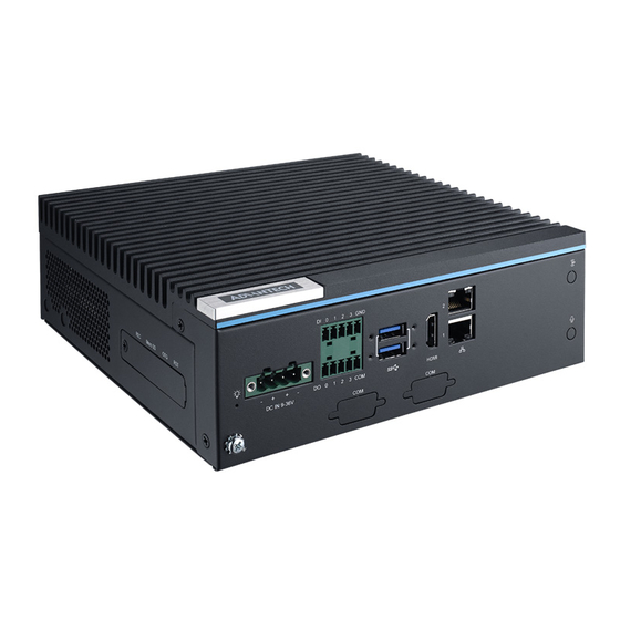
Introduction MIC-713 is pre-integrated with the NVIDIA® Jetson Orin NX™ or Orin Nano™, and is ideal for use in industrial AI applications. MIC-713 design includes 2 x Gigabit Ether- net LAN ports, 1 x HDMI video for display, 4ch-DI, 4ch-DO, 2 x RS-232/RS-422/RS- 485 (Internal pin header reserved), 6 x external USB3.2, 1 x internal Micro USB for... -
Page 11: Mechanical Specifications
; 15-5.6 A Environmental Specifications Operating temperature: -10 ~ 60°C (14 ~ 140°F)* Operating humidity: 95% @ 40°C (non-condensing) Storage temperature: -40 ~ 85°C (-40 ~ 185°F) Storage humidity: 60°C @ 95% RH non-condensing MIC-713 User Manual... - Page 12 MIC-713 User Manual...
-
Page 13: Chapter 2 System I/O Overview
Chapter System I/O Overview... -
Page 14: System I/O Overview
MIC-713 System I/O Overview MIC-713 User Manual... -
Page 15: Connectors
Connectors 2.2.1 Power Indicator The MIC-713 comes with a Power ON/OFF LED indicators on the front side to show its on status (Green LED) and Off/Suspend status (RED LED). MIC-713 User Manual... -
Page 16: 4In-4Out Di/Do
Table 2.1: Isolation digital input Number of Input Channels 2500 V Optical Isolation Dry contact: Logic1: Open Logic0: Close to ground Wet contact: Input Voltage VIH (max.)=60 V VIH (min.)= 5 V VIL (max.)= 2 V MIC-713 User Manual... -
Page 17: Usb 3.2
0.2 A max./Channel 2.2.3 USB 3.2 The MIC-713 provides two USB3.2 Gen2 ports in the front panel, and four USB3.2 Gen2 ports in the rear panel, suggest to choose 12 V (or above)/ 120 W (or above) adapter for using. -
Page 18: Ethernet (Lan)
2.2.4 Ethernet (LAN) The MIC-713 comes with two/five LAN Ports on the front side. Each Ethernet port is equipped with two LEDs. The Green LED indicates activity; the other Green-Amber LED indicates speed. 2 LAN SKU 5 LAN SKU Table 2.3: Ethernet (LAN) LED indicator... -
Page 19: Chassis Grounding Connection
Install the MIC device into the cabinet/rack system without I/O and power cables. System wiring: Ensure that all cabinet/rack system have been grounded together. Connect the ground of the power supply to the cabinet/rack system. Connect the ground pin of the MIC device to the cabinet/rack system. MIC-713 User Manual... -
Page 20: Dc-In Connector
NOTE: To take and swap the 4 pin phoenix connector from the system accessory box if the adapter only offers 2 pin/3 pin phoenix connectors. 2.2.7 HDMI Connector The MIC-713 provides an HDMI 2.0 type-A connector for displaying video. The maxi- mum resolution is 3840x2160 @60Hz. MIC-713 User Manual... -
Page 21: Line-Out & Microphone Jack (Optional)
2.2.8 Line-Out & Microphone Jack (Optional) The MIC-713 provides 3.5 mm type line-out (for headphones only) and a microphone jack for audio usage. The optional cable part number is 1700027920-01. 2.2.9 COM Port (Optional) The MIC-713 provides 2pcs COM port for RS-232/422/485 usage. The optional cable part number is 1700019968. -
Page 22: Can Bus Connector
2.2.10 CAN BUS Connector The MIC-713 provides a 9 pin CAN FD BUS connector. The pin descriptions is shown below. Table 2.4: CAN BUS connector Signal Description Reserved No connection CAN_L CAN Low bus line CAN_GND CAN_GND Reserved No connection... -
Page 23: Sma Half-Punched Holes
2.2.11 SMA Half-Punched Holes The MIC-713 provides up to 7 SMA half-punched holes, these holes can be installed for the antenna & related cable of Wi-Fi, Bluetooth, GPS, GNSS, 4G, 5G etc. MIC-713 User Manual... - Page 24 MIC-713 User Manual...
-
Page 25: Board Placement Overview
Chapter Board Placement Overview... -
Page 26: Board Placement Overview
MIC-713 Board Placement Overview MIC-713 User Manual... -
Page 27: Board Block Diagram
3.1.1 Board Block Diagram NOTE: Intel i350 is only for 5 LAN SKU. Realtek RTL8119L is only for 2 LAN SKU. MIC-713 User Manual... -
Page 28: Power Connector For Idoor Modules
MUST have a 24 V output type for the system when using an iDoor PoE LAN card. 3.1.3 Power Connector for PCIe Expansion Cards This connector can support an extra 12 V of power (up to 25 W) for PCIe cards. MIC-713 User Manual... -
Page 29: Mic & Line-Out Cable Header
3.1.4 Mic & Line-Out Cable Header The optional cable 1700027920-01 can be plugged into this header for audio usage. MIC-713 User Manual... -
Page 30: Com Port Deep Switch & Connector
Table 3.1: COM port deep switch & connector Mode Pin1 Pin2 Pin3 Pin4 RS-232 SW_COM1 RS-422 ON- Receiver Termina- SW_COM2 ON-Bypass RTS polar- tion Enable Setting ity OFF- Invert RTS OFF- Receiver Termina- RS-485 polarity tion Disable MIC-713 User Manual... -
Page 31: Power Connector For Sata Hdd/Ssd
3.1.6 Power Connector for SATA HDD/SSD This connector can provide power to a 2.5” HDD/SSD or a 3.5” HDD, the cable need to contact Advantech Sales/AE for detailed information. MIC-713 User Manual... -
Page 32: 4-Pin Fan Header
3.1.7 4-pin Fan Header For some scenarios, a 4-pin fan will be connected to this board. The maximum specification that each header can provide is 9.6 W. MIC-713 User Manual... -
Page 33: Pci Express Expansion Slot
3.1.8 PCI Express Expansion Slot MIC-713 offers a PCIe Gen4 x4 open-end slot (x4 link) for various usages, such as Ethernet, USB cards, etc. MIC-713 User Manual... -
Page 34: Deep Switch For M.2 3052 Slot
The default setting for pins 20 & 22 are OFF. Table 3.2: Deep switch for M.2 3052 slot Status SW1-1 (Pin 20) 1.8 V pull high SW1-2 (Pin 22) NC (Default) MIC-713 User Manual... -
Page 35: Poe Upgrade Kit (Optional) Related Connector
PoE Upgrade Kit (Optional) Related Connector LAN PoE Power Source Connector (54V) – This connector pass the 54 V power (from Advantech PoE board) to 4 PoE ports, each port can provide up to 15 W to device. PoE board Power connector (12 V) – This connector pass the 12 V (from moth- erboard) to Advantech PoE board. -
Page 36: M.2 3052 Slot & Related Sim Slot
M.2 3052 slot – This slot provides USB 2.0/3.2 signal for expansion cards. SIM slot for M.2 3052 slot – A NANO SIM card can be adopted into this slot if the M.2 3052 expansion card requests it for further usage. MIC-713 User Manual... -
Page 37: Mini Pcie Slot & Sim Slot For Mini Pcie Slot
Mini PCIe slot – This slot provides USB 2.0 and PCIe Gen3 x1 signal for expan- sion cards. SIM slot for Mini PCIe slot – A NANO SIM card can be adopted into this slot if the Mini PCIe expansion card requests it for further usage. MIC-713 User Manual... -
Page 38: M.2 2242/2280 Slot
Install “1910000747” in the stand-off, then install the M.2 M-Key 2242 card in the slot. 3.1.14 TPM2.0 Header This header is suitable for a TPM (Trusted Platform Module) 2.0 device, the Advant- ech part number is PCA-TPMSPI-00A1. MIC-713 User Manual... -
Page 39: Recovery Button/Reset Button/Micro Usb Connector
Mode” manually. (a) Shut down the MIC-713. (b) Connect to the HOST PC via MIC-713 Internal micro USB port with the USB cable. You can find this cable in the accessory box. (c) Press and hold the onboard recovery button. -
Page 40: Micro Sd Slot
If the extra data storage space is required, you can install a 64GB or above capacity Micro SD card on this slot for further usage. 3.1.17 GPIO Expansion Header The MIC-713 provides multi GPIO pins for developer usage. The pin definition is as below table. Table 3.3: GPIO expansion header Signal... - Page 41 MIC-713 User Manual...
-
Page 42: Uart Header
3.1.18 UART Header The MIC-713 provides a UART header for developer’s usage. The pin definition is as shown in the table below. Table 3.4: UART header Signal Description IO Voltage Level UART_TX UART Transmit 1.8 V UART_RX UART Receive 1.8 V... -
Page 43: Allxon Module Power/Control Header
3.1.19 Allxon Module Power/Control Header If an Allxon out-of-band module (Advantech PN: 98RV710AL00) will be installed on the motherboard, the necessary Advantech cable PN and motherboard pin definition is shown below. Table 3.5: Allxon module power/control header Function Advantech Cable PN Power 5 V FP_PWR1 (PIN1 &... -
Page 44: At/Atx Power Mode Jumper
3.1.20 AT/ATX Power Mode Jumper MIC-713 provides the AT/ATX power mode jumper for different scenario usage. Table 3.6: PSON1 Power Mode AT (Default) MIC-713 User Manual... -
Page 45: Deep Switch For Can Bus
3.1.21 Deep Switch for CAN Bus MIC-713 provides a deep switch for CAN bus to add a 120 ohm resistor or not to pre- vent signal reflection. The default setting of pin 1 is OFF. Table 3.7: Deep switch for CAN bus... -
Page 46: Mipi Slot
3.1.22 MIPI Slot The MIC-713 provides an MIPI slot. It can be installed with the Advantech GMSL2 card (2 channel card with FAKRA connectors, Advantech PN 968DD00294). There are 3 screws (Advantech PN 1930005673-11) necessary for the Advantech GMSL2 card installation. These screws are pre-installed on the motherboard. -
Page 47: System Installation
Chapter System Installation... -
Page 48: Removing Bottom Cover
Removing Bottom Cover There are a total of 8 screws (1930007979) which need to be removed before open- ing the bottom cover. MIC-713 User Manual... -
Page 49: Bracket Installing
Take the mounting bracket (Advantech PN: 1960110505N001, MOUNTING Bracket for MIC-713 Powder 432C) from the accessory box. Secure with 4 screws (Advantech PN: 1930007259-01, M4x4L F/S D=8.5 H=1.5 (2+) ST/H BZn-NK) and install the system on a table. Type 1:... - Page 50 Type 2: MIC-713 User Manual...
- Page 51 Mounting bracket (1960110505N001, MOUNTING Bracket for MIC-713 Powder 432C) MIC-713 User Manual...
-
Page 52: Solution Kit Exploded Diagram
Wire mount (sa-1013a)for IPC-602 A1 1962675110 FAN GUARD 60*60mm IPC-6751 (MFG-06) A1 1750000323 FAN 60*60*13 5400R 0.36A 12V FOR ACP-2320 1960109252N001 DEV KIT Bracket for MIC-713 Powder 432C 96920071300 MIC-713_CB A101-2 1990000755S000 RJ45 COVER PINGOOD EBPC-5250 A1 NET-01-PPB 2000035349 Product Label FP MIC-713_PG00 A1... -
Page 53: System Exploded Diagram
968DD00271 NVIDIA Jetson Orin NX-16G 1960110398N001 Bottom Cover for MIC-713 Powder 432C 1950027792N011 Front Panel U WO PSE for MIC-713 Powder 432C 1 1935140630 R/S(TW) D=8.2 H=3.4 + M4*6L ST Zmc-3 1970005636T001 HS R3 Other 25W 195x174.3x19.65 mm SCCPU 1 Thermal-Pad 13.9x13.9x1mm TP K=8 Eapus... - Page 54 MIC-713 User Manual...
- Page 55 MIC-713 User Manual...
- Page 56 No part of this publication may be reproduced in any form or by any means, such as electronically, by photocopying, recording, or otherwise, without prior written permission from the publisher. All brand and product names are trademarks or registered trademarks of their respective companies. © Advantech Co., Ltd. 2023...
- Page 57 用户手册 MIC-713 ® AI 推理系统,搭配 NVIDIA Jetson Orin NX ™ /Orin Nano ™...
- Page 58 收集您所遇到的问题的信息 (例如,CPU 主频、使用的研华产品及其它软件、 硬件等) 。请注意屏幕上出现的任何不正常信息显示。 打电话给您的供货商,描述故障问题。请借助手册,产品和任何有帮助的信息。 如果您的产品被诊断发生故障,请从您的供货商那里获得 RMA (Return Material Authorization) 序列号。这可以让我们尽快地进行故障产品的回收。 请仔细地包装故障产品,并在包装中附上完整的售后服务卡片和购买日期证明 (如销售发票) 。我们对无法提供购买日期证明的产品不提供质量保证服务。 把相关的 RMA 序列号写在外包装上,并将其运送给销售人员。 符合性声明 FCC A 级 注意:根据 FCC 规则第 15 款,本设备已经过检测并被判定符合 A 级数字设备标准。 这些限制旨在为商业环境下的系统操作提供合理保护,使其免受有害干扰。本设备会 产生、耗费和发射无线电频率能量,如果没有按照手册说明正确安装和使用,可能会 对无线电通讯造成有害干扰。此时,用户需自行解决干扰问题。 料号:2002071300 第一版 台湾印刷 2023 年 9 月 MIC-713 用户手册...
- Page 59 2-port 10GBase-T NIC w PCIE-2221NP-00A1E Advantech PCIe x4 lan 卡 Intel X550 PCIe 插槽 (PCIe Gen4 x4 PCIE-2201E Advantech PCIE 2 ports SFP+ 82599ES PCIe x8 lan 卡 插槽,x4 信号) PCIe x4, 4-port USB 3.0 扩 PCE-USB4-00A1E Advantech PCIe x4 USB3.0 卡 展卡...
- Page 60 SQF MICRO SD C10 3D TLC 64G Micro SD 卡 SQF-MSDV1-64GDD2C Advantech (-25~85°C) 仅限 MIC-713 系 MIC-733 PoE 板,配备包装 PoE 板 98917330010 Advantech 96917330010 列 5 lan sku TPM 2.0 模块 by SPI,用于 TPM 模块 PCA-TPMSPI-00A1 Advantech CPU 卡,A101-1 备注:兼容设备列表所列之设备可能会因厂商之产品时程规画终结而无法于市面上购...
- Page 61 安全措施 - 静电防护 为了保护您和您的设备免受伤害或损坏。请遵照以下安全措施: 操作设备之前,请务必断开机箱电源,以防触电。不可在电源接通时接触 CPU 板或其它板上的任何组件。 在更改任何配置之前请断开电源,以免在您连接跳线或安装卡时,瞬间电涌损坏 敏感电子组件。 MIC-713 用户手册...
- Page 62 MIC-713 用户手册...
- Page 63 产品特点............2 1.2.1 主要特点 ..........2 表 1.1: 处理器.........2 机械规格............3 电源规格............4 环境规格............4 第 2 章 系统接口信息 ......5 MIC-713 系统接口信息..........6 介面............7 2.2.1 电源指示灯 ..........7 2.2.2 4 路数码输入 / 数码输出端口 .......8 表 2.1: 隔离式数码输入.........8 表 2.2: 隔离式数码输出.........8 2.2.3 USB3.2 ...........9 2.2.4 网络 ............10 表...
- Page 64 表 3.7: 控制器区域网络指拨开关 ....... 37 3.1.22 行动产业处理器适配卡槽 ........ 38 第 4 章 系统安装 ......39 卸除底盖 ............40 安装支架 ............41 解决方案套件爆炸图 ..........44 表 4.1: 解决方案套件爆炸图 ......44 标准系统爆炸图 ..........45 表 4.2: 标准系统爆炸图 ....... 45 MIC-713 用户手册 viii...
- Page 65 第 1 章 产品信息...
-
Page 66: 产品简介
路数码输入与 4 路数字输出、 2 个 RS-232/RS- 422/RS-485 ( 以 pin header 的形式 预留于机器内部 )、外部留有 6 个 USB3.2、内部则有 1 个 Micro USB 用于系统还 原、1 个 mini-PCIE ( 讯号: PCIe + USB)、1 个 M.2 2280 NVMe(Signal:PCIE x1) 以及 1 个工储存数据用的 Micro SD 卡槽。另外,MIC-713 支持 iDoor 与 iModule 藉以提供更多的整合与使用弹性。 产品特点... -
Page 67: 机械规格
1 x Micro SD 卡槽 2 x NANO SIM 卡槽 ( 供相对应之 Mini PCIe & M.2 3052 卡片使用 ) 机械规格 标准系统尺寸:194.8 x 174.3 x 65.85 mm (7.67" x 6.86" x 2.59") 参考重量:2.05 kg( 不含包材 ) 194.80 MIC-713 用户手册... -
Page 68: 电源规格
电源规格 电源类型:AT/ATX 电源输入:DC 9-36 V,15-5.6 A 环境规格 工作温度: -10 ~ 60°C (14 ~ 140°F)* 工作湿度: 95% @ 40°C (非冷凝)) 储存温度:-40 ~ 85°C (-40 ~ 185°F) 储存湿度:60°C @ 95% RH, 无凝结 MIC-713 用户手册... - Page 69 第 2 章 系统接口信息...
-
Page 70: Mic-713 系统接口信息
MIC-713 系统接口信息 MIC-713 用户手册... -
Page 71: 电源指示灯
介面 2.2.1 电源指示灯 MIC-713 前面板设有电源开 / 关指示灯,该灯可指示系统开机状态 (绿色 LED)和系 统关机 / 休眠状态 (红色 LED) 。 MIC-713 用户手册... -
Page 72: 路数码输入 / 数码输出端口
2.2.2 4 路数码输入 / 数码输出端口 MIC-713 在本机前面板提供了一组支持隔离式 4 路数码输入与 4 路数码输出的接头。 0 1 2 3 GND DO 0 1 2 3 COM 表 2.1:隔离式数码输入 Number of Input Channels 2500 V Optical Isolation Dry contact: Logic1: Open Logic0: Close to ground ... -
Page 73: Usb3.2
2.2.3 USB3.2 MIC-713 在前面板上提供了 2 个 USB3.2 Gen2 以及在后面板上提供了 4 个 USB3.2 Gen2,建议选择 12V (或以上)/120W (或以上)电源适配器来使用。 在前面板上的 2 个 USB3.2 Gen2 接口可以提供最高至 15W/ 接口的电源输出。 在后面板上的 4 个 USB3.2 Gen2 接口可以提供最高至 4.5W/ 接口的电源输出。 注 ! 若使用 9V 适配器,则 6 个 USB 接口仅可提供总额 30W 之输出。... - Page 74 2.2.4 网络 MIC-713 在本机前面板提供了两组 / 五组网络端口,其上方各有两个 LED 灯,绿色 LED 灯表示网络运作状态,绿橘双色灯表示网络速度。 2 lan SKU 5 lan SKU 表 2.3:网络 Green LED Blinking LAN No connection LAN Link Activity on this port Green-Amber LED Green Amber Speed Speed Speed 10 Mbps 1G bps 100 Mbps MIC-713 用户手册...
-
Page 75: 系统接地连接
2.2.5 系统接地连接 请使用绿黄双色的接地线 (16 AWG)并搭配系统接地螺丝确实接地。 2.2.6 直流电输入接头 连接线使用直流电 须由专业人员安装。 只使用铜导体。 需选择合适的线径。 适合 14 AWG 的接线盒扭矩值为 7 lb in。 系统运作容许电压范围为 9 V 至 36 V 系统运作容许电流范围为 15 A 至 5.6 A. 附注:若电源适配器仅提供 2 针 /3 针形式凤凰接头,可使用系统配件盒内随附的 4 针凤凰接头作更换使用 MIC-713 用户手册... -
Page 76: Hdmi 接头
2.2.7 HDMI 接头 MIC-713 在前窗提供一个 Type-A 形式的 HDMI 2.0 接头供外接屏幕使用,其最高分 辨率为 3840 x 2160 @60Hz。 2.2.8 线性输出与麦克风接头 ( 选购 ) MIC-713 提供一个 3.5mm 形式的线性输出孔 ( 仅供耳机使用 ) 以及一个麦克风接孔, 若有需要此功能 , 需另外选购研华料号 1700027920-01 之线材。 MIC-713 用户手册... -
Page 77: 串口 ( 选购 )
2.2.9 串口 ( 选购 ) MIC-713 提供 2 个 RS-232/422/485 串口可满足相对应需求,若需要此串口,需另外 选购研华料号 1700019968 之线材。 针对此串口的指拨开关功能调整 , 请参阅 3.1.5 章节。 MIC-713 用户手册... -
Page 78: 控制器局域网络接口
2.2.10 控制器局域网络接口 MIC-713 提供一个 9 针形式之控制器区域网络 FD 接口,功能定义说明如下表。 表 2.4:控制器局域网络接口 Signal Description Reserved No connection CAN_L CAN Low bus line CAN_GND CAN_GND Reserved No connection CAN_Shield CAN_Shield CAN_GND CAN_GND CAN_H CAN High bus line Reserved No connection No connection MIC-713 用户手册... -
Page 79: 反级性天线安装半冲断孔
2.2.11 反级性天线安装半冲断孔 MIC-713 提供多至 7 个反级性天线安装半冲断孔 , 供给使用者针对其需求所要搭配安 装之无线 / 蓝芽 / 全球卫星定位 /4G/5G 功能卡片与天线使用。 MIC-713 用户手册... - Page 80 MIC-713 用户手册...
- Page 81 第 3 章 主板组件配置信息...
-
Page 82: Mic-713 主板组件配置信息
MIC-713 主板组件配置信息 MIC-713 用户手册... -
Page 83: 主板方块图
3.1.1 主板方块图 注: Intel i350 仅用于 5 LAN SKU。 Realtek RTL8119L 仅用于 2 LAN SKU。 MIC-713 用户手册... -
Page 84: Idoor 模块专用电源接头
3.1.2 iDoor 模块专用电源接头 此接头为专门供给 iDoor 相关装置使用,此接头输出之电压将与供给主板 DC-IN 接 头的电源电压相同。 若 iDoor 要安装 PoE 扩充卡片,请注意供给 DC-IN 接头的电压必须为 24 V 。 3.1.3 PCIe 扩充卡电源接头 此接头为专门供应额外 12 V 电源给 PCIe 扩展卡使用,供应上限为 25W。 MIC-713 用户手册... -
Page 85: 麦克风与线性输出接头
3.1.4 麦克风与线性输出接头 若有需要使用到麦克风与线性输出功能,请搭配研华料号 1700027920-01 之产品使 用,此产品需额外选购。 MIC-713 用户手册... -
Page 86: 串行端口接头与指拨开关
3.1.5 串行端口接头与指拨开关 以下表格为串口指拨开关之设定说明,默认值为 RS-232 模式。 表 3.1:COM 端口开关设置 Mode Pin1 Pin2 Pin3 Pin4 RS-232 SW_COM1 RS-422 ON- Receiver SW_COM2 Termination Enable ON-Bypass RTS polarity Setting OFF-Receiver OFF-Invert RTS polarity RS-485 Termination Disable MIC-713 用户手册... -
Page 87: Sata 硬盘 / 固态硬盘电源接头
3.1.6 SATA 硬盘 / 固态硬盘电源接头 此接头可提供电源给 2.5 寸或 3.5 寸之硬盘 / 固态硬盘使用,若需相关电源线之研 华料号,请洽研华之业务 / 应用工程师以获得进一步之协助与信息。 MIC-713 用户手册... -
Page 88: 4-Pin 风扇接头
3.1.7 4-pin 风扇接头 本主板可提供 2 个 4-pin (2.54mm pitch)风扇接头供客户之相关场域使用。 每个接头可提供 12V 电压输出,风扇对其抽载之上限不可超过 9.6W。 MIC-713 用户手册... -
Page 89: Pci Express 扩充插槽
3.1.8 PCI Express 扩充插槽 MIC-713 主板提供了一个可供网卡 /USB 卡 … 等使用的 PCIe Gen4 x4 (x4 link)扩 展槽 , 扩展槽尾部为非封闭形式 , 让扩展卡在使用上更具弹性。 MIC-713 用户手册... -
Page 90: M.2 3052 指拨开关
3.1.9 M.2 3052 指拨开关 在某些特定卡片使用时会需要针对 M.2 3052 卡槽上第 20 与 22 脚位做电位调整 , 指 拨开关之默认值为 OFF, 说明请参阅下表。 表 3.2:M.2 3052 指拨开关 Status SW1-1 (Pin 20) 1.8 V pull high SW1-2 (Pin 22) NC (default) MIC-713 用户手册... -
Page 91: Poe 升级套件 ( 选购品 ) 相关接头
PoE 升级套件 ( 选购品 ) 相关接头 LAN PoE 电源供给接头 (54 V) – 此接头可分别提供 54 V 电源给 4 个 PoE 网 络接口使用,每端口最大可供应 15 W 给予终端装置。 PoE 板卡电源接头 (12V)- 此接头传导来自主板上的 12 V 电源给选购之 PoE 电 源板卡。 PoE 版卡控制接头 - 此接头为预留之内部开发功能使用。 以下图表说明 PoE 网络接口之电源转换流程与电源来源。 MIC-713 用户手册... -
Page 92: M.2 3052 与相关之 Sim 卡槽
3.1.11 M.2 3052 与相关之 SIM 卡槽 M.2 3052 卡槽 - 此卡槽以 USB 2.0/3.2 讯号供给扩展卡片使用。 SIM 卡槽 – 若 M.2 3052 之装置有需求,可以搭配下图指示位置之 NANO SIM 卡槽来做使用。 MIC-713 用户手册... -
Page 93: Mini Pcie 与相关之 Sim 卡槽
SIM 卡槽 – 若 Mini PCIe 之装置有需求 , 可以搭配下图指示位置之 NANO SIM 卡槽来做使用。 3.1.13 M.2 2242/2280 卡槽 此卡槽提供 PCIe Gen4 x1 讯号给 M.2 M-Key 形式的 2242/2280 装置来安装使用。 若需要使用 M.2 2242 装置 , 需要另外选购研华料号 1910000747 之零件,安装该零 件后再行装入 M.2 2242 装置于卡槽上。 MIC-713 用户手册... -
Page 94: 信赖平台模块 2.0 接头
3.1.14 信赖平台模块 2.0 接头 此接头可供信赖平台模块 2.0 版本装置使用 , 研华相对应之选购产品料号为 PCA- TPMSPI-00A1。 MIC-713 用户手册... -
Page 95: 还原按钮 / 重启按钮 /Micro Usb 接头
3.1.15 还原按钮 / 重启按钮 /Micro USB 接头 当需要对 MIC-713 进行更新时 , 首先必须要进入 “ 强制 USB 还原模式 ”, 在此模式 下可以针对 MIC-713 的系统软体或是对内部装置组态配置做修改。 以下为更新步骤说明: 准备一台主机 , 关于主机的细部说明 , 请参阅以下网址 https://www.advantech.com/en/campaign/industrial-ai-iot-solution- nvidia/resource 在进行刷新 MIC-713 之前,请确认 MIC-713 已经手动进入 “ 强制 USB 还原模 式 ” 接着进行以下操作:... -
Page 96: Micro Sd 卡槽
3.1.16 Micro SD 卡槽 此卡槽提供 USB2.0 讯号供 Micro SD 卡片使用。 当有额外储存空间需求时,请于本卡槽插入至少 64 GB 以上容量的 Micro SD 卡片以 供后续使用。 3.1.17 GPIO 扩展接头 MIC-713 提供多个 GPIO 接头供开发者使用,详细功能与定义可参阅下表。 表 3.3: GPIO 扩展接头 Signal Description IO Voltage Level 3.3 V Power +3.3V 3.3 V Power +5V 3.3 V... - Page 97 MIC-713 用户手册...
-
Page 98: 通用非同步收发传输器接头
3.1.18 通用非同步收发传输器接头 MIC-713 提供 UART 接头供开发者使用,详细功能定义可参阅下表。 表 3.4: 通用非同步收发传输器接头 Signal Description IO Voltage Level UART_TX UART Transmit 1.8 V UART_RX UART Receive 1.8 V MIC-713 用户手册... -
Page 99: Allxon 模块专用电源 / 控制接头
3.1.19 Allxon 模块专用电源 / 控制接头 当 Allxon 远程控制卡 (研华料号:98RV710AL00)被安装在主板上时 , 请选购并搭配 下表内列出的线材做使用。相关针脚图示与定义说明如下方所示。 表 3.5: Allxon 模块专用电源/控制接头 Function Advantech Cable PN Power 5 V FP_PWR1 (PIN1 & PIN2) 1700034663-01 Power Button JFP1 (PIN1 & PIN2) 1700034664-01 Reset Button JFP1 (PIN3 & PIN4) 1700034665-01 MIC-713 用户手册... -
Page 100: At/Atx 电源模式调整跳帽
3.1.20 AT/ATX 电源模式调整跳帽 MIC-713 提供跳帽供使用者依据自身需求去做相对应调整,模式对照请参阅下表。 表 3.6: PSON1 针脚 电源模式 AT(预设) MIC-713 用户手册... -
Page 101: 控制器区域网络指拨开关
3.1.21 控制器区域网络指拨开关 MIC-713 针对控 制器 区域 网络提 供了 120 奥 姆阻值 的指 拨开关 来防 止讯 号反射 指拨开关预设设定为 OFF,调整说明请见下表。 表 3.7: 控制器区域网络指拨开关 Function Add 120 ohm Remove 120 ohm (default) MIC-713 用户手册... -
Page 102: 行动产业处理器适配卡槽
3.1.22 行动产业处理器适配卡槽 MIC-713 提供一个行动产业处理器适配卡槽供安装研华设计之 GMSL2 卡片 ( 选购品, 双路 FAKRA 接头卡片,研华料号 968DD00294) 使用。 有三颗螺丝必须搭配安装使用 ( 研华料号 1930005673-11),这三颗螺丝已先预锁附在 相对应铜柱上。 安装示意图如下: MIC-713 用户手册... - Page 103 第 4 章 系统安装...
-
Page 104: 卸除底盖
卸除底盖 卸除 MIC-713 底盖前须先移除 8 颗螺丝 ( 研华料号 1930007979),螺丝位置示意如 下。 MIC-713 用户手册... -
Page 105: 安装支架
安装支架 从配盒内取出安装支架 ( 研华料号 1960110505N001) 两支。 将支架藉由锁附四颗螺丝 ( 研华料号 1930007259-01) 固定在系统上,一共有两 种固定方式,请参阅下图。 类型 1: MIC-713 用户手册... - Page 106 类型 2: MIC-713 用户手册...
- Page 107 安装支架(1960110505N001,MIC-713 Powder 432C 的安装支架) MIC-713 用户手册...
-
Page 108: 解决方案套件爆炸图
Wire mount(sa-1013a)for IPC-602 A1 1962675110 FAN GUARD 60*60mm IPC-6751 (MFG-06) A1 1750000323 FAN 60*60*13 5400R 0.36A 12V FOR ACP-2320 1960109252N001 DEV KIT Bracket for MIC-713 Powder 432C 96920071300 MIC-713_CB A101-2 1990000755S000 RJ45 COVER PINGOOD EBPC-5250 A1 NET-01-PPB 2000035349 Product Label FP MIC-713_PG00 A1... -
Page 109: 标准系统爆炸图
968DD00271 NVIDIA Jetson Orin NX-16G 1960110398N001 Bottom Cover for MIC-713 Powder 432C 1950027792N011 Front Panel U WO PSE for MIC-713 Powder 432C 1 1935140630 R/S(TW) D=8.2 H=3.4 + M4*6L ST Zmc-3 1970005636T001 HS R3 Other 25W 195x174.3x19.65 mm SCCPU 1990027474N020 Thermal-Pad 13.9x13.9x1mm TP K=8 Eapus PG80B 2... - Page 110 MIC-713 用户手册...
- Page 111 MIC-713 用户手册...
- Page 112 使用前请检查核实产品的规格。本手册仅作为参考。 产品规格如有变更,恕不另行通知。 未经研华公司书面许可,本手册中的所有内容不得通过任何途径以任何形式复制、翻 印、翻译或者传输。 所有其他产品名或商标均为各自所属方的财产。 © 研华公司 2023...
- Page 113 用戶手冊 MIC-713 ® AI 推理系統,搭配 NVIDIA Jetson Orin NX™/Orin Nano™...
- Page 114 我們將會酌情收取材料費、人工服務費用。請聯繫您的銷售人員瞭解詳細情況。 如果 您認為您購買的產品出現了故障,請遵循以下步驟: 如果您認為您購買的產品出現了故障,請遵循以下步驟: 收集您所遇到的問題的資訊 (例如,CPU 主頻、使用的研華產品及其它軟體、 硬件等) 。請注意螢幕上出現的任何不正常資訊顯示。 打電話給您的供應商,描述故障問題。請借助手冊,產品和任何有説明的資訊。 如果您的產品被診斷發生故障,請從您的供應商那裡獲得 RMA (Return Material Authorization)序號。這可以讓我們儘快地進行故障產品的回收。 請仔細地包裝故障產品,並在包裝中附上完整的售後服務卡片和購買日期證明 (如銷售發票) 。我們對無法提供購買日期證明的產品不提供品質保證服務。 把相關的 RMA 序號寫在外包裝上,並將其運送給銷售人員。 申請商:研華股份有限公司 地址:台北市內湖區瑞光路 26 巷 20 弄 1 號 電話:02-77323399 料號: 2002071300 第一版 臺灣印刷 2023 年 9 月 MIC-713 用戶手冊...
- Page 115 這些限制旨在為商業環境下的系統操作提供合理保護,使其免受有害干擾。本設備會 產生、耗費和發射無線電頻率能量,如果沒有按照手冊說明正確安裝和使用,可能會 對無線電通訊造成有害干擾。 本產品於國內裝置使用時,其電源僅限使用機架電源模組所提供直流電源輸入,不得 使用交流電源及附加其他電源轉換裝置提供電源,其電源輸入電壓及電流請依說明書 規定使用。 包裝清單 安裝之前,用戶需確認包裝中含有下面所列各項。如果有任何專案與列表不符,請立 即聯繫您的經銷商。 1 x MIC-713 1 x 電源接頭 (4P) 2 x DI/DO 接頭 (5P) 2 x 支架 1 x 中國 ROHS 表 1 x 手冊 ( 線上下載 ) ...
- Page 116 MIC-713 配備 NVIDIA Orin Orin Nano 4GB ADV MIC-713-ON2A1 Advantech Nano 4GB AI 系統 PN is 968DD00350 系統 MIC-713 配備 NVIDIA Orin NX Orin NX 16GB ADV MIC-713-OX4A1 Advantech 16GB AI 系統 PN:968DD00271 MIC-713 配備 NVIDIA Orin NX Orin NX 8GB ADV...
- Page 117 產品資訊 如需本產品或研華其它產品的更多資訊,請訪問我們的網站: http://www.advantech.com 如需技術支援與服務,請訪問 MIC-713 的技術支援網站: https://www.advantech.com/en/products/ai-computer-systems/sub_965e4edb- fb98-429e-89ed-9a0a8435a7be 請在網站上註冊您的產品並免費獲取得 2 個月的延長保固: http://www.register.advantech.com 安全指示 請仔細閱讀此安全操作說明。 請妥善保存此用戶手冊供日後參考。 用濕抹布清洗設備前,請從插座拔下電源線。請不要使用液體或去汙噴霧劑清洗 設備。 對於使用電源線的設備,設備周圍必須有容易接觸到的電源插座。 請不要在潮濕環境中使用設備。 請在安裝前確保設備放置在可靠的平面上,意外跌落可能會導致設備損壞。 設備外殼的開口是用於空氣對流,從而防止設備過熱。請不要覆蓋這些開口。 當您連接設備到電源插座上前,請確認電源插座的電壓是否符合要求。 請將電源線佈置在人們不易絆到的位置,並不要在電源線上覆蓋任何雜物。 請注意設備上的所有警告標識。 如果長時間不使用設備,請將其同電源插座斷開,避免設備被超標的電壓波動損 壞。 請不要讓任何液體流入通風口,以免引起火災或者短路。 請不要自行打開設備。為了確保您的安全,請由經過認證的工程師來打開設備。 如遇下列情況,請由專業人員來維修: 電源線或者插頭損壞; 設備內部有液體流入; 設備曾暴露在過於潮濕的環境中使用; 設備無法正常工作,或您無法通過用戶手冊來使其正常工作; 設備跌落或者損壞; 設備有明顯的外觀破損。 免責聲明:該安全指示符合 IEC 704-1 的要求。研華公司對其內容的準確性不...
- Page 118 MIC-713 用戶手冊...
- Page 119 2.2.9 序列埠 ( 選購 ) ..........13 2.2.10 控制器區域網路埠 ........14 表 2.4: 控制器區域網路埠......14 2.2.11 反級性天線安裝半沖斷孔 .........15 第 3 章 主機板元件配置概述 ....17 MIC-713 主機板元件配置概述 ........18 3.1.1 主機板方塊圖 ..........19 3.1.2 iDoor 模組專用電源接頭 ........20 3.1.3 PCIe 擴充卡電源接頭 ........20 3.1.4 麥克風與線性輸出接頭 ........21 3.1.5 序列埠接頭與指撥開關 ........22 表 3.1: COM 端口开关设置......22 3.1.6 SATA 硬碟...
- Page 120 3.1.22 行動產業處理器介面卡槽 ........ 38 第 4 章 系統安裝 ......39 卸除底蓋 ............40 安裝支架 ............41 解決方案套件爆炸圖 ..........44 表 4.1: 解決方案套件爆炸圖 ......44 標準系統爆炸圖 ..........45 表 4.2: 標準系統爆炸圖 ....... 45 附錄 A 限用物質含有情況標示聲明書 .... 47 MIC-713 用戶手冊 viii...
- Page 121 第 1 章 產品概述...
-
Page 122: 產品簡介
產品簡介 MIC-713 搭載 NVIDIA® Jetson Orin NX ™ 或是 Orin Nano ™, 是邊緣 AI 運算應用的理 想選擇。MIC-713 標準系統提供 2 個網路埠、1 個 HDMI 用於連接影像輸出、4 路數 位輸入與 4 路數位輸出、2 個 RS-232/RS- 422/RS-485 ( 以 pin header 的形式預留 於機器內部 )、外部留有 6 個 USB3.2、內部則有 1 個 Micro USB 用於系統還原、1 個... -
Page 123: 機械規格
1 x Micro SD 卡槽 2 x NANO SIM 卡槽 ( 供相對應之 Mini PCIe & M.2 3052 卡片使用 ) 機械規格 標準系統尺寸:194.8 x 174.3 x 65.85 mm (7.67" x 6.86" x 2.59") 參考重量:2.05 kg( 不含包材 ) 194.80 MIC-713 用戶手冊... -
Page 124: 電源規格
電源規格 電源類型:AT/ATX, 電源輸入:DC 9-36 V,15-5.6 A 環境規格 工作溫度:-10 ~ 60°C (14 ~ 140°F)* 工作濕度:95% @ 40°C,無凝結 儲存溫度:-40 ~ 85°C (-40 ~ 185°F) 儲存濕度:60°C @ 95% RH,無凝結 MIC-713 用戶手冊... -
Page 125: 系統介面概述
第 2 章 系統介面概述... - Page 126 MIC-713 系 介面概述 MIC-713 用 手...
- Page 127 介面 2.2.1 源指示 MIC-713 前面板 有 源 指示 可指示系 ( 色 LED)和系 / 休眠 ( 色 LED) 。 MIC-713 用 手...
-
Page 128: 路數位輸入 / 數位輸出埠
2.2.2 4 路數位輸入 / 數位輸出埠 MIC-713 在本機前面板提供了一組支援隔離式 4 路數位輸入與 4 路數位輸出的接 頭。 0 1 2 3 GND DO 0 1 2 3 COM 表 2.1:隔離式數位輸入 Number of Input Channels 2500 V Optical Isolation Dry contact: Logic1: Open Logic0: Close to ground ... -
Page 129: Usb3.2
2.2.3 USB3.2 MIC-713 在前面板上提供了 2 USB3.2 Gen2 以及在 面板上提供了 4 USB3.2 Gen2,建 12 V (或以上)/120 W (或以上) 源 配器 使用。 在前面板上的 2 USB3.2 Gen2 可以提供最高至 15 W/ 的 源 出。 在 面板上的 4 USB3.2 Gen2 可以提供最高至 4.5 W/ 的 源 出。... - Page 130 2.2.4 路 MIC-713 在本 前面板提供了 / 五 路 ,其上方各有 , 色 LED 表示 路 作 , 橘 色 表示 路速度。 2 lan sku 5 lan 表 2.3: 路 Green LED Blinking LAN No connection LAN Link Activity on this port...
- Page 131 合 14 AWG 的接 盒扭矩值 7 lb in。 系 作容 至 36 V 。 系 作容 流 15 A 至 5.6 A。 附 :若 源 配器 提供 2 针 /3 针形式 凰接 ,可使用系 配件盒 附的 4 针 凰接 作更 使用 MIC-713 用 手...
- Page 132 Type-A 形式的 HDMI 2.0 接 供外接 幕使用 , 其最高解 度 3840x2160 @60Hz。 2.2.8 性 出 克 接 MIC-713 提供一 3.5 mm 形式的 性 出孔 ( 供耳 使用 ) 以及一 克 接孔, 若有需要此功能,需另外 研 料 1700027920-01 之 材。 MIC-713 用 手...
- Page 133 2.2.9 序列 MIC-713 提供 2 RS-232/422/485 序列 可 足相 需求,若需要此序列 ,需 另外 研 料 1700019968 之 材。 此序列 的指 功能 整, 3.1.5 章 。 MIC-713 用 手...
- Page 134 形式之控制器 域 路 FD ,功能定 明如下表。 表 2.4: 控制器 域 路 Signal Description Reserved No connection CAN_L CAN Low bus line CAN_GND CAN_GND Reserved No connection CAN_Shield CAN_Shield CAN_GND CAN_GND CAN_H CAN High bus line Reserved No connection No connection MIC-713 用 手...
- Page 135 2.2.11 反 性天 安 半 孔 MIC-713 提供多至 7 反 性天 安 半 孔,供 使用者 其需求所要搭配安 之 芽 / 全球 星定位 /4G/5G 功能卡片 天 使用。 MIC-713 用 手...
- Page 136 MIC-713 用戶手冊...
-
Page 137: 主機板元件配置概述
第 3 章 主機板元件配置概述... - Page 138 MIC-713 主 板 件配置概述 MIC-713 用 手...
- Page 139 3.1.1 主 板方 注: 5 LAN SKU。 Intel i350 用 2 LAN SKU。 Realtek RTL8119L 用 MIC-713 用 手...
- Page 140 置使用,此接 出之 供 主 板 DC-IN 接 的 源 相同。 若 iDoor 要安 充卡片, 注意供 DC-IN 接 的 必 24 V 。 3.1.3 PCIe 充卡 源接 此接 供 外 12 V 源 PCIe 充卡使用,供 上限 25 W。 MIC-713 用 手...
- Page 141 3.1.4 克 性 出接 若有需要使用到 克 性 出功能, 搭配研 料 1700027920-01 之 品使 用,此 品需 外 。 MIC-713 用 手...
-
Page 142: 表 3.1:Com 端口开关设置
以下表格 序列 指 之 定 明, 值 RS-232 模式。 表 3.1:COM 端口开关设置 Mode Pin1 Pin2 Pin3 Pin4 RS-232 SW_COM1 RS-422 ON- Receiver SW_COM2 Termination Enable ON-Bypass RTS polarity Setting OFF- Receiver OFF- Invert RTS RS-485 Termination polarity Disable MIC-713 用 手... - Page 143 3.1.6 SATA 硬 / 固 硬 源接 此接 可提供 源 或 3.5 之硬 /固 硬 使用,若需相 源 之研 料 , 洽研 之 / 用工程 以 得 一步之 助 。 MIC-713 用 手...
- Page 144 3.1.7 4-pin 扇接 本主 板可提供 2 4-pin(2.54 mm pitch) 扇接 供客 之相 域使用。 每 接 可提供 12 V 出, 扇 其抽 之上限不可超 9.6 W。 MIC-713 用 手...
-
Page 145: Pci Express 擴充插槽
3.1.8 PCI Express 充插槽 MIC-713 主 板提供了一 可供 卡/USB 卡…等使用的 PCIe Gen4 x4(x4 link) 充槽, 充槽尾部 非封 形式, 充卡在使用上更具 性。 MIC-713 用 手... - Page 146 3.1.9 M.2 3052 指 在某些特定卡片使用 需要 M.2 3052 卡槽上第 20 位做 位 整, 指 之 值 OFF, 明 下表。 表 3.2: M.2 3052 指 Status SW1-1 (Pin 20) 1.8 V pull high SW1-2 (Pin 22) NC (default) MIC-713 用 手...
- Page 147 源供 接 (54 V) – 此接 可分 提供 54 V 源 路 使用,每 最大可供 15 W 予 端 置。 PoE 板卡 源接 (12V)-此接 自主 板上的 12 V 源 之 PoE 源板卡。 PoE 版卡控制接 -此接 留之 部 功能使用。 以下 表 明PoE 路 之 源 流程 源 源。 MIC-713 用 手...
-
Page 148: 3052 與相關之 Sim 卡槽
3.1.11 M.2 3052 相 之 SIM 卡槽 M.2 3052 卡槽 - 此卡槽以 USB 2.0/3.2 供 充卡片使用。 SIM 卡槽 – 若 M.2 3052 之 置有需求,可以搭配下 指示位置之 NANO SIM 卡槽 做使用。 MIC-713 用 手... -
Page 149: Mini Pcie 與相關之 Sim 卡槽
SIM 卡槽 – 若 Mini PCIe 之 置有需求,可以搭配下 指示位置之 NANO SIM 卡槽 做使用。 3.1.13 M.2 2242/2280 卡槽 此卡槽提供 PCIe Gen4 x1 M.2 M-Key 形式的 2242/2280 置 安 使用。 若需要使用 M.2 2242 置,需要另外 研 料 1910000747 之零件,安 零 件 再行 入 M.2 2242 置 卡槽上。 MIC-713 用 手... - Page 150 3.1.14 信 平台模 2.0 接 此接 可供信 平台模 2.0 版本 置使用,研 相 之 品料 PCA- TPMSPI-00A1。 MIC-713 用 手...
-
Page 151: 還原按鈕 / 重啟按鈕 /Micro Usb 接頭
在 行刷新 MIC-713 之前, MIC-713 已 手 入“ 制 USB 原模 式”。 接 行以下操作: MIC-713 。 (b) 在 MIC-713 配件盒 取出 Micro USB , 其 接 主 MIC-713 之 。 (c) 按下且持 住MIC-713主 板上的 原按 (d) 按一下重 按 (e) 五秒之 , 先前持... -
Page 152: Micro Sd 卡槽
SPI Master Out/Slave In 1.8 V I2S_SCLK I2S Audio Clock 1.8 V SPI1_CS0 SPI Chip Select 0 1.8 V SPI1_CS1 SPI Chip Select 1 1.8 V GPIO06G GPIO 1.8 V GPIO07 GPIO 1.8 V GPIO12 GPIO 1.8 V MIC-713 用 手... - Page 153 MIC-713 用 手...
- Page 154 3.1.18 通用非同步收 器接 MIC-713 提供 UART 接 供 者使用, 功能定 可 下表。 表 3.4: 通用非同步收 器接 Signal Description IO Voltage Level UART_TX UART Transmit 1.8 V UART_RX UART Receive 1.8 V MIC-713 用 手...
- Page 155 表 3.5: Allxon 模 用 源/控制接 Function Advantech Cable PN Power 5 V FP_PWR1 (PIN 1 & PIN 2) 1700034663-01 Power Button JFP1 (PIN 1 & PIN 2) 1700034664-01 Reset Button JFP1 (PIN 3 & PIN 4) 1700034665-01 MIC-713 用 手...
- Page 156 3.1.20 AT/ATX 源模式 整 接器 MIC-713 提供 接器供使用者依 自身需求去做相 整,模式 照 下表。 表 3.6: PSON1 源模式 AT( ) MIC-713 用 手...
- Page 157 3.1.21 控制器 域 路指 MIC-713 控制器 域 路提供了 120 姆阻值的指 防止 反射指 定 OFF, 整 明 下表。 表 3.7: 控制器 域 路指 Function Add 120 ohm Remove 120 ohm (default) MIC-713 用 手...
- Page 158 3.1.22 行 理器介面卡槽 MIC-713 提供一 行 理器介面卡槽供安 研 之 GMSL2 卡片( 品, 路 FAKRA 接 卡片,研 料 968DD00294)使用。 有三 螺 必 搭配安 使用(研 料 1930005673-11), 三 螺 已先 附 在相 柱上。 安 示意 如下: MIC-713 用 手...
- Page 159 第 4 章 系統安裝...
- Page 160 卸除底 卸除 MIC-713 底 前 先移除 8 螺 (研 料 1930007979),螺 位置示意如 下。 MIC-713 用 手...
- Page 161 安 支架 配盒 取出安 支架(研 料 1960110505N001) 支。 支架藉由 附四 螺 (研 料 1930007259-01)固定在系 上,一共有 固定方式, 下 。 型 1: MIC-713 用 手...
- Page 162 型 2: MIC-713 用 手...
- Page 163 安 支架尺寸 MIC-713 用 手...
- Page 164 Wire mount(sa-1013a)for IPC-602 A1 1962675110 FAN GUARD 60*60mm IPC-6751 (MFG-06) A1 FAN 60*60*13 5400R 0.36A 12 V FOR ACP-2320 1750000323 1960109252N001 DEV KIT Bracket for MIC-713 Powder 432C 96920071300 MIC-713_CB A101-2 1990000755S000 RJ45 COVER PINGOOD EBPC-5250 A1 NET-01-PPB 2000035349 Product Label FP MIC-713_PG00 A1...
- Page 165 968DD00271 NVIDIA Jetson Orin NX-16G 1960110398N001 Bottom Cover for MIC-713 Powder 432C 1950027792N011 Front Panel U WO PSE for MIC-713 Powder 432C 1 1935140630 R/S(TW) D=8.2 H=3.4 + M4*6L ST Zmc-3 HS R3 Other 25 W 195x174.3x19.65 mm SCCPU 1970005636T001 1990027474N020 Thermal-Pad 13.9x13.9x1mm TP K=8 Eapus PG80B 2...
- Page 166 MIC-713 用戶手冊...
- Page 167 附錄 A 限用物質含有情況標示 聲明書...
- Page 168 限用物質含有情況標示聲明書 Declaration of the Presence Condition of the Restricted Substances Marking PLM MDR NO: MDR-006990 型號 (型式) :MIC-713-OX4A1; MIC-713-OX3A1; MIC-713-ON3A1; MIC-713-ON2A1; 設備名稱:電腦 MIC-713S-OX4A1; MIC-713S-OX3A1; Equipment name MIC-713S-ON3A1; MIC-713S-ON2A1 Type designation (Type) 限用物質及其化學符號 Restricted substances and its chemical symbols 單元 六價鉻...
- Page 169 MIC-713 系列型號 MIC-713S-OX3A1 MIC-713S-ON2A1 MIC713SOX2301-T MIC713SON2301-T MIC713OX2301-T MIC713ON2301-T MIC-713S-OX3A2 MIC-713S-ON2A2 MIC713SOX2302-T MIC713SON2302-T MIC713OX2302-T MIC713ON2302-T MIC-713S-OX3B1 MIC-713S-ON2B1 MIC713SOX2303-T MIC713SON2303-T MIC713OX2303-T MIC713ON2303-T MIC-713S-OX3B2 MIC-713S-ON2B2 MIC713SOX2401-T MIC713SON2401-T MIC713OX2401-T MIC713ON2401-T MIC-713S-OX3C1 MIC-713S-ON2C1 MIC713SOX2402-T MIC713SON2402-T MIC713OX2402-T MIC713ON2402-T MIC-713S-OX4A1 MIC-713S-ON3A1 MIC713SOX2403-T MIC713SON2403-T MIC713OX2403-T MIC713ON2403-T MIC-713S-OX4A2 MIC-713S-ON3A2...
- Page 170 使用前請檢查核實產品的規格。本手冊僅作為參考。 產品規格如有變更,恕不另行通知。 未經研華公司書面許可,本手冊中的所有內容不得通過任何途徑以任何形式複製、翻 印、翻譯或者傳輸。 所有的產品品牌或產品型號均為公司之注冊商標。 © 研華公司 2023...
Need help?
Do you have a question about the MIC-713 and is the answer not in the manual?
Questions and answers