Table of Contents
Advertisement
Quick Links
Advertisement
Table of Contents

Related Manuals for Advantech FWA-6510


Summary of Contents for Advantech FWA-6510
- Page 1 FWA-6510 H/W Installation APPROVALS Name (printed) Title Signature Date...
- Page 2 FWA-6510 H/W installation Version: V1.0 Page 2 of 21 HISTORY Revision Date Person Description V1.0...
-
Page 3: Table Of Contents
FWA-6510 H/W installation Version: V1.0 Page 3 of 21 CONTENT INDEX Hardware installation Introduction ................4 Open Chassis cover ..................….4 CPU & heat-sink Installation................5 Memory module installation................9 Extend cable & module installation ..............11 Riser card installation ..................13 Close Chassis Cover .................. -
Page 4: Hardware Installation Introduction
1. HARDWARE INSTALLATION INTRODUCTION Open Chassis cover 1. Kindly use screwdriver to unlock 2 side screws & chassis rear screw. Side screw Rear screw 2. Kindly push top cover back about 1.5cm, and pick up top cover, it may remove FWA-6510 Chassis cover... -
Page 5: Cpu & Heat-Sink Installation
FWA-6510 H/W installation Version: V1.0 Page 5 of 21 CPU & heat-sink Installation 1. Kindly unlock FAN duct’s 2 screws 2. Kindly pull a “OPEN 1st” lever of CPU socket , pull another lever of CPU socket and pull back load plate... - Page 6 FWA-6510 H/W installation Version: V1.0 Page 6 of 21 3. Kindly remove a protected cover from socket. 4. Kindly put CPU on the socket, and please checks CPU’s gaps and socket’s prominence, please don’t put wrong...
- Page 7 FWA-6510 H/W installation Version: V1.0 Page 7 of 21 5. Kindly lay down load plate; close a “close 1st” lever of CPU socket, and close another lever of CPU socket 6. Kindly smear the HEAT SINK COMPOUND on CPU well mixed...
- Page 8 FWA-6510 H/W installation Version: V1.0 Page 8 of 21 7. Please use screwdriver to fix heat-sink module and please follow diagonal to fix screw.
-
Page 9: Memory Module Installation
2. When customer installs 2 CPU in system, the minimum RAM requirement is 4 PCs, and it needs to install in A1/C1/E1/G1 DIMM socket. 3. If customer installs CPU in FWA-6510, A CPU needs to install in CPU socket 1 , the minimum RAM requirement is 2 PCs, and it needs to install in A1/C1 DIMM socket. - Page 10 FWA-6510 H/W installation Version: V1.0 Page 10 of 21 3. When CPU & Memory installs finish, kindly install FAN duct in chassis.
-
Page 11: Extend Cable & Module Installation
FWA-6510 H/W installation Version: V1.0 Page 11 of 21 Extend cable & module installation 1. If customer needs to use FWA-6510 VGA function, kindly install VGA cable (P/N: 1700019367) into CN15... - Page 12 FWA-6510 H/W installation Version: V1.0 Page 12 of 21 2. Kindly covers & don’t close chassis cover, and pull out VGA cable from chassis when customer uses FWA-6510 VGA function. 3. If customer needs to debug system boot issue, please install “Port80 module”(option) into CN 9...
-
Page 13: Riser Card Installation
1. Kindly use screwdriver to unlock front plate’s screw and remove front plate from Chassis 2. FWA-6510 Riser card only support PCIe X1/X4/X8 riser card, Please don’t install PCIe X16 riser card 3. Kindly use screwdriver to unlock plate’s screw, and remove IO card holder. - Page 14 FWA-6510 H/W installation Version: V1.0 Page 14 of 21 Kindly use screwdriver to lock riser card and IO card holder 5. Kindly use screwdriver to lock riser card in FWA-6510 chassis...
-
Page 15: Close Chassis Cover
Page 15 of 21 Close Chassis Cover 1. FWA-6510’s cover has 4 short posts, When user has to cover on top cover, short posts need to place in track 2. Kindly close chassis cover and use screwdriver to lock 3 chassis screws,... -
Page 16: Hdd And Hdd Tray Installation
FWA-6510 H/W installation Version: V1.0 Page 16 of 21 HDD and HDD tray installation 1. Kindly unlock HDD orange lock key. 2. Kindly push blue line button, the handle HDD tray will auto pop up, please pull HDD tray from chassis... - Page 17 FWA-6510 H/W installation Version: V1.0 Page 17 of 21 4. Kindly use screwdriver to lock 4 screws , let 2.5” HDD to fix in HDD tray Kindly insert HDD tray into Chassis, and lock HDD orange lock key.
-
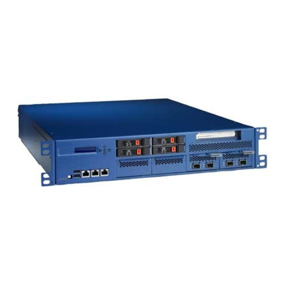
Page 18: Front Panel Connector Introduction
2. MGMT (Manage) LAN port: It is Intel 82574L LAN port, and it is a BMC LAN port too. User can use this port to remote control FWA-6510 by network, and it can use this LAN port to control FWA-6510 BMC (IPMI) function. -
Page 19: Led, Usb And Power Button Introduction
LED, USB and power button introduction Panel LED It is an alarm LED, When FWA-6510 has an alarm event or turn off, and the LED will show Amber It is location LED, User may key-in IPMI command to enable this LED... - Page 20 FWA-6510 H/W installation Version: V1.0 Page 20 of 21 USB Port, The front panel of FWA-6510 has two USB port. HDD LED 1. Green LED is a HDD active LED, when green LED turns on, it means HDD is reading/writing.
- Page 21 25 sec. and then execute BIOS boot up procedure. Boot procedure of FWA-6510 is depending on Memory size, it needs to wait 30 ~ 60 sec. 2. If BMC function is crash, BIOS will boot system after 90 sec, user needs to re-flash BMC firmware after...
Need help?
Do you have a question about the FWA-6510 and is the answer not in the manual?
Questions and answers