Lincoln Electric VRTEX 360 COMPACT Operator's Manual
Hide thumbs
Also See for VRTEX 360 COMPACT:
- Service manual (171 pages) ,
- Operator's manual (52 pages) ,
- Operator's manual (58 pages)
Table of Contents
Advertisement
Quick Links
Operator's Manual
®
VRTEX
360 COMPACT
Register your machine:
www.lincolnelectric.com/register
Authorized Service and Distributor Locator:
www.lincolnelectric.com/locator
Save for future reference
Date Purchased
Code: (ex: 10859)
Serial: (ex: U1060512345)
IM10600
| Issue D ate 2/21
© Lincoln Global, Inc. All Rights Reserved.
For use with machines having Code Numbers:
13142
+1.888.935.3878
Advertisement
Table of Contents
Troubleshooting

Subscribe to Our Youtube Channel
Related Manuals for Lincoln Electric VRTEX 360 COMPACT


Summary of Contents for Lincoln Electric VRTEX 360 COMPACT
- Page 1 Operator’s Manual ® VRTEX 360 COMPACT For use with machines having Code Numbers: 13142 Register your machine: www.lincolnelectric.com/register Authorized Service and Distributor Locator: www.lincolnelectric.com/locator Save for future reference Date Purchased Code: (ex: 10859) Serial: (ex: U1060512345) IM10600 | Issue D ate 2/21 +1.888.935.3878 ©...
- Page 2 VRTEX 360 COMPACT INSTALLATION ® THANK YOU FOR SELECTING A QUALITY PRODUCT BY KEEP YOUR HEAD OUT OF THE FUMES. DON’T get too close to the arc. LINCOLN ELEC TRIC. Use corrective lenses if necessary to stay a reasonable distance away from the arc.
- Page 3 W117.2-1974. A Free copy of “Arc Welding Safety” booklet E205 is available from the Lincoln Electric Company, 2.d. All welders should use the following procedures in order to 22801 St. Clair Avenue, Cleveland, Ohio 44117-1199.
- Page 4 VRTEX 360 COMPACT INSTALLATION ® SAFETY ELECTRIC SHOCK ARC RAYS CAN BURN. CAN KILL. 3.a. The electrode and work (or ground) circuits are 4.a. Use a shield with the proper filter and cover plates to protect your electrically “hot” when the welder is on. Do eyes from sparks and the rays of the arc when welding or not touch these “hot”...
- Page 5 VRTEX 360 COMPACT INSTALLATION ® SAFETY WELDING AND CUTTING CYLINDER MAY EXPLODE IF SPARKS CAN CAUSE DAMAGED. FIRE OR EXPLOSION. 7.a. Use only compressed gas cylinders containing the correct shielding gas for the process used 6.a. Remove fire hazards from the welding area. If and properly operating regulators designed for this is not possible, cover them to prevent the welding sparks the gas and pressure used.
- Page 6 2004/108/EC. It was manufactured in conformity with a national standard that implements a harmonized standard: EN 60974-10 Electromagnetic Compatibility (EMC) Product Standard for Arc Welding Equipment. It is for use with other Lincoln Electric equipment. It is designed for industrial and professional use. Introduction All electrical equipment generates small amounts of electromagnetic emission.
- Page 7 VRTEX 360 COMPACT INSTALLATION ® SAFETY Electromagnetic Compatibility (EMC) The size of the surrounding area to be considered will depend on the structure of the building and other activities that are taking place. The surrounding area may extend beyond the boundaries of the premises. Methods of Reducing Emissions Mains Supply Welding equipment should be connected to the mains supply according to the manufacturer’s recommenda-...
-
Page 8: Table Of Contents
VRTEX 360 COMPACT VRTEX ® 360 COMPACT TABLE OF CONTENTS INSTALLATION ® Page Installation ........................Graphic Symbols That May Appear On This Machine Or In This Manual ..........1 Technical Specifications ........................2 Safety Precautions ...........................3 Select Suitable Location ........................4 Environmental Area .........................4 Stacking ............................4 Tilting ..............................4 Transport ............................5... - Page 9 VRTEX 360 COMPACT INSTALLATION ® Page Maintenance ........................Cleaning & Maintenance ........................41 Troubleshooting ......................How To Use Troubleshooting Guide ....................42 Troubleshooting Guide ......................43-44 Diagrams .......................... Dimensions ...........................45 Wiring Diagram ..........................46 Parts .................... parts.lincolnelectric.com...
-
Page 10: Installation
VRTEX 360 COMPACT INSTALLATION ® GRAPHIC SYMBOLS THAT MAY APPEAR ON THIS MACHINE OR IN THIS MANUAL FUSE INPUT VOLTAGE INPUT CURRENT WARNING OR CAUTION Documentation must be con- sulted in all cases where this symbol is displayed. INPUT POWER POWER BUTTON VIRTUAL REALITY READ THIS MANUAL... -
Page 11: Technical Specifications
VRTEX 360 COMPACT INSTALLATION ® TECHNICAL SPECIFICATIONS INPUT MODEL DESCRIPTION INPUT VOLTAGE INPUT CURRENT ± 10% (MAX.) K4914-1 SINGLE USER 115/230 VAC (50/60 HZ) 2/1A SINGLE PHASE WARNING THIS PRODUCT INCORPORATES A PROTECTIVE EARTH CIRCUIT IN THE AC POWER CORD. THE AC PLUG SHOULD ONLY BE INSERTED INTO A SOCKET OUTLET PROVIDED WITH A PROTECTIVE EARTH CONTACT. -
Page 12: Safety Precautions
VRTEX 360 COMPACT INSTALLATION ® Read entire installation section before starting Immediately, stop using the Headset and consult your physician if you installation. experience any of the following symptoms: • Double vision or inability to focus on the display. Do not place objects on the VR Table, Arm or on •... -
Page 13: Select Suitable Location
VRTEX 360 COMPACT INSTALLATION ® SELECT SUITABLE When exposed to radio frequency noise of 3Vrms in the frequency range of 50-80 Mhz, the system may experience a “rest” and/or other LOCATION unintended operation. If this occurs, prevention of future occurrences may be achieved by moving the system away from any potential sources of radio frequency noise such as radio communication towers or the like. -
Page 14: Transport
In the case of noise on the AC port being an issue, a noise suppressing ferrite bead can be added to the AC power cord which will eliminate the interference. Please contact your Lincoln Electric Support Center for details. -
Page 15: Product Description
VRTEX 360 COMPACT INSTALLATION ® PRODUCT DESCRIPTION The VRTEX is a virtual reality arc welding trainer. This computer based training system is an educational tool designed to allow students to practice their welding technique in a simulated environment. It promotes the efficient transfer of welding skills from the classroom to the welding booth, while reducing material waste and energy consumption associated with traditional welding training. -
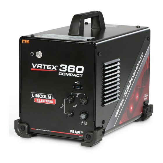
Page 16: User Interface Overview
VRTEX 360 COMPACT INSTALLATION ® USER INTERFACE OVERVIEW See Figure 2 for locations of main unit control and connection points. 1. The Power Button powers on/off the VRTEX system. 2. The USB Port is used to upload software and download user data from the system. - Page 17 VRTEX 360 COMPACT INSTALLATION ® See Figure 3 for locations of rear connection points. 1. Monitor Connections, plug the three cables in the monitor bundle to these ports. 2. Headset connection. 3. Main Power Input. 4. External Monitor Connection (HDMI). 5.
-
Page 18: Component Overview
VRTEX 360 COMPACT INSTALLATION ® COMPONENT OVERVIEW See Figure 4 for locations of VRTEX 360 Compact system ® components. 1. Coupon Arm and Arm Holder 2. Touchscreen Monitor 3. Headset 4. Coupons 5. GTAW Filler VR GTAW/SMAW/GMAW 6. Foot Amptrol 7. -
Page 19: Hardware Specifics
VRTEX 360 COMPACT INSTALLATION ® HARDWARE SPECIFICS Figure 6 – VR SMAW device VR GMAW/FCAW GUN The VR gun has a trigger that is used during the simulation of GMAW and FCAW processes to initiate and maintain the simulated welding arc. - Page 20 Figure 8 – Headset components 5. 6” Pipe Schedule 40 ADJUSTMENT 6. Lap Joint STRAPS 7. Pipe On Plate The coupons along with all VR devices have been factory calibrated by The Lincoln Electric Company. Figure 9 – VR Coupons EARPHONES...
- Page 21 VRTEX 360 COMPACT INSTALLATION ® STAND ASSEMBLY POLE The Stand Assembly is comprised of the Clamp and Pole Assembly, Hole numbers 1 through 9 indicate position of welding for program Arm Holder, Coupon Arm, two Pivot Lock Pins and a Collar Pin. The accuracy.
-
Page 22: Hardware Uncrating
VRTEX 360 COMPACT INSTALLATION ® HARDWARE UNCRATING Figure 13- Monitor connections 1. “MACHINE SKID” – Using a utility knife, carefully remove the two plastic bands securing the carton to the skid. See Figure 12. Figure 12 – Machine Skid 7. Once connected, place monitor upright. Route the cables between the stand and body of monitor ensuring the monitor and stand are sitting directly on work surface. - Page 23 VRTEX 360 COMPACT INSTALLATION ® Figure 15 – Headset connections 16. “CLAMP AND POLE ASSEMBLY” – Remove the contents from box. Install assembly on work space surface. Tighten clamp knob as necessary to ensure assembly is solidly affixed to work space surface.
- Page 24 VRTEX 360 COMPACT INSTALLATION ® 18. Install Arm Holder by placing over pole and sliding down to just 20. Connect the Coupon Arm cable to the back of the machine. See Figure 23. above desired height. Partially insert Collar Pin into corresponding hole.
-
Page 25: Device Labels
VRTEX 360 COMPACT INSTALLATION ® DEVICE LABELS 22. Connect the desired welding device to the corresponding connectors on the front of the machine. See Figure 25. Figure 25 – Welding machine connectors The devices for each VRTEX machine are calibrated for optimal performance. -
Page 26: Operation
WELDING / CUTTING SELECTION SCREEN Welding and cutting are available with the VRTEX. The user can select either at startup. To enable Cutting contact a Lincoln Electric representation. Figure 30 – Welding / cutting selection screen NOTE: Main power disconnect located in the rear of the machine. -
Page 27: User Mode
VRTEX 360 COMPACT OPERATION (USER MODE) ® USER MODE LOGIN SCREEN SYSTEM SETUP INFORMATION OVERVIEW This page allows the user to: (See Figure 31) When setting up the virtual equipment, the user must set the welding parameters (e.g. wire feed speed for VR GMAW) within the ranges •... -
Page 28: Coupon Configuration Selection Screen
VRTEX 360 COMPACT OPERATION (USER MODE) ® PROCESS SELECTION 1. USB Indicator The circular USB icon in the upper right corner of the screen indicates SCREEN the presence of a USB memory stick in the front of the machine. Translucent: no USB stick connected, Green: USB connected and ready. -
Page 29: Environment Screen
VRTEX 360 COMPACT OPERATION (USER MODE) ® Figure 36 – Table setup & device status screen Figure 38 – VR coupon (unlocked position) (showing SMAW device needed but not connected) ENVIRONMENT SCREEN Figure 37 – Table setup & device status screen (showing all needed devices are connected) OVERVIEW The VRTEX comes pre-configured with a number of different virtual... -
Page 30: Parameter Setup Screen
VRTEX 360 COMPACT OPERATION (USER MODE) ® PARAMETER SETUP SCREEN OVERVIEW On this screen, the user selects the welding parameters. See Figures 40 and 41. The welding parameters must be entered according to the tolerance editor. Figure 40 – Gas selection screen Figure 41 –... -
Page 31: Virtual Welding Overview
VRTEX 360 COMPACT OPERATION (USER MODE) ® VIRTUAL WELDING VISUAL CUES OVERVIEW Visual cues are aids to help users learn faster. The travel speed, CTWD, arc length and travel/work angle cues indicate whether the user is within the tolerances set in the tolerances editor. Generally, While a user is welding, observers can see the welder’s view, Live these cues are color coded as well as symbolic. -
Page 32: Gtaw Cues
VRTEX 360 COMPACT OPERATION (USER MODE) ® The Travel/Work Angle cue can be used with the SMAW, GMAW, The Weave cue can be used to space the weave so the outer ring GTAW or FCAW processes. See Figure 45. The goal of this cue is to is green (good weave spacing), set the width of the weave so line is center the circle in the cross hair and keep the color green. - Page 33 VRTEX 360 COMPACT OPERATION (USER MODE) ® Figure 50 – Filler movement Figure 52 – Postflow AMPERAGE NEW COUPON 1. The footpedal location matches the real life movement of the Selecting the blue new coupon menu icon replaces the current amperage controller.
-
Page 34: Laser Screen
VRTEX 360 COMPACT OPERATION (USER MODE) ® TECHNIQUE PARAMETERS END PASS When the user selects the green “End Pass” menu icon, the pass is scored, a snapshot of the weld is taken and the percentages of The upper right area of the screen shows the technique parameters the weld containing discontinuities are calculated. -
Page 35: Pass Number
VRTEX 360 COMPACT OPERATION (USER MODE) ® Position is the user’s ideal weld root location. This location Travel Angle is the angle between the electrode and the workpiece in the direction of travel. See Figure 58. The upper right area of the can change with each pass. -
Page 36: Bead Render
VRTEX 360 COMPACT OPERATION (USER MODE) ® BEAD RENDER SCORE An image of the completed pass appears in the middle of the screen. A score for each parameter is calculated. The closer each parameter is to the ideal value, the higher the score will be (out of 100). The total score of the scoring section is calculated as an average of all DISCONTINUITY parameters. -
Page 37: Instructor Mode
VRTEX 360 COMPACT OPERATION (INSTRUCTOR MODE) ® INSTRUCTOR MODE AND Figure 63 – Instructors mode screen ADMIN ACCESS TO ENTER INSTRUCTOR MODE 1. Touch the “Key” icon located in the lower left corner of the screen. See Figure 61. Figure 61 – Menu and instruction key 2. -
Page 38: Weldometer
VRTEX 360 COMPACT OPERATION (INSTRUCTOR MODE) ® WELDOMETER RESET TRIP Selecting Reset Trip zeroes out all items in the trip column. This allows an instructor to track VR material savings over a certain time period. OVERVIEW SAVE TO FILE The Weldometer tracks virtual consumables, arc time, base material and gas usage. -
Page 39: Tolerance Editor
VRTEX 360 COMPACT OPERATION (INSTRUCTOR MODE) ® TOLERANCE EDITOR CHOOSE TOLERANCE SETUP Displays the list of all tolerance settings currently stored on the unit. All units ship with default settings and learning levels. If the user OVERVIEW creates multiple tolerance files, the file in use is selected by using the red arrow icons. - Page 40 VRTEX 360 COMPACT OPERATION (INSTRUCTOR MODE) ® CUSTOMIZE TOLERANCE LEVELS 10. The equipment settings screen allows for the modification of the following welding parameters (See Figure 68): The following steps describe the procedure to change tolerances for • Wire Feed Speed the VRTEX: •...
- Page 41 VRTEX 360 COMPACT OPERATION (INSTRUCTOR MODE) ® 12. The welding technique parameters screen allows the modification 13. The pattern & aim screen allows the user to change the type of of (See Figure 70): pattern being used (stringer, box weave, straight weave, whip, triangle weave) and the position of the root of the weld.
-
Page 42: Scoring Modules
VRTEX 360 COMPACT OPERATION (INSTRUCTOR MODE) ® SCORING MODULES 14. The whip & travel screen allows for the modification of technique parameters relating to the whipping welding technique and travel speed including (See Figure 73): • Dime Spacing After welding a pass, the user can now see whether each defect/ discontinuity was within acceptable standards (passed) or not (failed). -
Page 43: Settings
VRTEX 360 COMPACT OPERATION (INSTRUCTOR MODE) ® UPDATE SOFTWARE Selecting this option loads a newer version of the software if one is available on a USB inserted in the front of the machine. Updating to a different version may shut down or restart the system. After updating, the system may need to be shut down and restarted for changes to be implemented. -
Page 44: Additional Features
VRTEX 360 COMPACT OPERATION ® ADDITIONAL FEATURES Figure 79 WELDING WITHOUT THE HEADGEAR Designed to allow users the ability to weld without being totally immersed inside the virtual environment. Users now have the option to view the welding process in the virtual reality headgear, or choose instead to use the Auto Camera and positioning on the touchscreen monitor. - Page 45 VRTEX 360 COMPACT OPERATION ® BEND TEST Figure 84 – Sample A Many welding codes require bend tests as part of the testing required to qualify welders according to welding procedures specifications (WPS’s). By adding the virtual bend test to the VRTEX, a student can see what causes a bend test to pass and fail. ...
- Page 46 VRTEX 360 COMPACT OPERATION ® SELECTING ROOT OR FACE Figure 89 – Completed bend test Select the direction of the bend to the ROOT or FACE. Once the desired sample is chosen, press the green BEND icon to begin the bend test.
- Page 47 VRTEX 360 COMPACT OPERATION ® THE CERTIFICATE REPLAY MODE The BEND TEST CERTIFICATE is located in the STUDENT REPORT, The Video Replay feature in your VRTEX provides the ability to view which can be saved and accessed if there is a USB memory device your virtual weld video once you have completed it.
- Page 48 VRTEX 360 COMPACT OPERATION ® LEARNING LEVELS SELECTING A LEARNING LEVEL The Learning Levels, or Tolerance Level, feature in your VRTEX Once Tolerance has been selected, toggle between the different provides 3 skill levels (Entry Level, Intermediate and Advanced) for Learning Levels.
- Page 49 VRTEX 360 COMPACT OPERATION ® Figure 99 SELECTING A COUPON FOR RESTARTS The general set up is the same as setting up for the other joints. The user signs in on the “Login” screen and presses the green continue button. This will take the user to the “Joint Selection” screen. There are two coupons that can be used for practicing Restarts: Practice Plate and Pipe on Plate.
-
Page 50: Cleaning & Maintenance
VRTEX 360 COMPACT MAINTENANCE ® CLEANING & BATTERY The backup batteries (two for each computer unit) are located MAINTENANCE behind the access panel on the rear of the machine. See Figures 110 and 111. The “AA” backup batteries can be accessed by using a T-30 torx nutdriver to remove the two screws and the panel. -
Page 51: Troubleshooting
HOW TO USE TROUBLESHOOTING GUIDE WARNING Service and Repair should only be performed by Lincoln Electric Factory Trained Personnel. Unauthorized repairs per- formed on this equipment may result in danger to the technician and machine operator and will invalidate your factory warranty. -
Page 52: Troubleshooting Guide
VRTEX 360 COMPACT TROUBLESHOOTING ® TROUBLESHOOTING GUIDE Observe Safety Guidelines detailed in the beginning of this manual. PROBLEMS POSSIBLE AREAS OF RECOMMENDED (SYMPTOMS) MISADJUSTMENT(S) COURSE OF ACTION The weld coupon image is a different Either the wrong coupon is on the stand or Select the menu icon and select ‘change configuration than the physical coupon. - Page 53 VRTEX 360 COMPACT TROUBLESHOOTING ® TROUBLESHOOTING GUIDE Observe Safety Guidelines detailed in the beginning of this manual. PROBLEMS POSSIBLE AREAS OF RECOMMENDED (SYMPTOMS) MISADJUSTMENT(S) COURSE OF ACTION Previous weld pass data is not accessible “End Pass” must be activated before Use the touch screen to go to pass number on the LASER screen.
-
Page 54: Dimensions
VRTEX 360 COMPACT DIAGRAMS ® Figure 103 – Dimensions (cm) -
Page 55: Wiring Diagram
VRTEX 360 COMPACT DIAGRAMS ® Figure 104 – Wiring diagram... - Page 56 Lincoln Electric for advice or information about their use of our products. We respond to our customers based on the best information in our possession at that time. Lincoln Electric is not in a position to warrant or guarantee such advice and assumes no liability, with respect to such information or advice.
Need help?
Do you have a question about the VRTEX 360 COMPACT and is the answer not in the manual?
Questions and answers